2002 CHRYSLER CARAVAN heating
[x] Cancel search: heatingPage 478 of 2399

FIRING ORDERAUTO SHUT DOWN RELAY
DESCRIPTION
The relay is located in the Power Distribution Cen-
ter (PDC). For the location of the relay within the
PDC, refer to the PDC cover for location. Check elec-
trical terminals for corrosion and repair as necessary
OPERATION
The ASD sense circuit informs the PCM when the
ASD relay energizes. A 12 volt signal at this input
indicates to the PCM that the ASD has been acti-
vated. This input is used only to sense that the ASD
relay is energized.
When energized, the ASD relay supplies battery
voltage to the fuel injectors, ignition coils and the
heating element in each oxygen sensor.
When energized, the ASD relay provides power to
operate the injectors, ignition coil, generator field, O2
sensor heaters (both upstream and downstream),
(EGR solenoid and PCV heater if equipped) and also
provides a sense circuit to the PCM for diagnostic
purposes. If the PCM does not receive 12 volts from
this input after grounding the ASD relay, it sets a
Diagnostic Trouble Code (DTC). The PCM energizes
the ASD any time there is a Crankshaft Position sen-
sor signal that exceeds a predetermined value. The
ASD relay can also be energized after the engine has
been turned off to perform an O2 sensor heater test,
if vehicle is equipped with OBD II diagnostics.
As mentioned earlier, the PCM energizes the ASD
relay during an O2 sensor heater test. This test is
performed only after the engine has been shut off.
The PCM still operates internally to perform several
checks, including monitoring the O2 sensor heaters.
CAMSHAFT POSITION
SENSOR
DESCRIPTION
The camshaft position sensorfor the 3.3/3.8L is
mounted in the front of the timing case cover (Fig. 6)
and the camshaft position sensor for the 2.4L is
mounted on the end of the cylinder head (Fig. 3).
FIRING ORDER 2.4L
Firing Order 1-2-3-4-5-6 3.3/3.8L
1 - Electrical Connector
RSIGNITION CONTROL8I-3
IGNITION CONTROL (Continued)
ProCarManuals.com
Page 486 of 2399

IGNITION CONTROL
TABLE OF CONTENTS
page page
GLOW PLUG
DESCRIPTION..........................1
OPERATION............................1
GLOW PLUG RELAY
DESCRIPTION..........................1
OPERATION............................1CAMSHAFT POSITION SENSOR
DESCRIPTION..........................2
OPERATION............................2
REMOVAL.............................2
INSTALLATION..........................2
GLOW PLUG
DESCRIPTION
Glow plugs are used to help start a cold or cool
engine (Fig. 1). The glow plugs will heat up and glow
to heat the combustion chamber of each cylinder. An
individual glow plug is used for each cylinder. Each
glow plug is threaded into the left side of the cylinder
head below the cylinder head cover/intake manifold.
OPERATION
Each glow plug will momentarily draw approxi-
mately 25 amps of electrical current during the ini-
tial key ªONº cycle. This is on a cold or cool engine.
After heating the current draw will drop to approxi-
mately 9±12 amps per plug.
Total momentary cuurent draw for all four glow
plugs is approximately 100 amps on a cold engine
dropping to a total of approximately 40 amps after
the plugs are heated.
Electrical operation of the glow plugs is controlled
by two glow plug relays. Each glow plug relay con-
trols two glow plugs. Refer to glow plug relays for
more information.
GLOW PLUG RELAY
DESCRIPTION
There are two glow plug relays. These relays are
located in the Power Distribution Center (PDC) in
the engine compartment (Fig. 2).
OPERATION
When the ignition (key) switch is place in the ON
position, a signal is sent to the ECM relating current
engine coolant temperature. This signal is sent from
the engine coolant temperature sensor.
After receiving this signal, the ECM will determine
if, when and for how long of a period the glow plug
relays should be activated. This is done before, dur-
ing and after the engine is started. Whenever the
glow plug relays are activated, it will control the 12
volt 100 amp circuit for the operation of the four
glow plugs. Each relay control two glow plugs.
Fig. 1 GLOW PLUG
Fig. 2 RELAY LOCATIONS
1 - GLOW PLUG RELAY
2 - RADIATOR SUPPORT
3 - CHARGE AIR COOLER OUTLET HOSE
4 - COOLING FAN RELAY
5 - UPPER RADIATOR HOSE
6 - EGR SOLENOID
RGIGNITION CONTROL8Ia-1
ProCarManuals.com
Page 587 of 2399

POWER MIRRORS
TABLE OF CONTENTS
page page
POWER MIRRORS
DESCRIPTION.........................46
OPERATION...........................46
DIAGNOSIS AND TESTING - POWER
MIRRORS...........................46
AUTOMATIC DAY / NIGHT MIRROR
DESCRIPTION.........................47
OPERATION...........................47
DIAGNOSIS AND TESTING - AUTOMATIC DAY
/ NIGHT MIRROR......................48
REMOTE SWITCH
DIAGNOSIS AND TESTING - REMOTE
SWITCH............................49REMOVAL.............................49
INSTALLATION.........................49
SIDEVIEW MIRROR
REMOVAL.............................49
POWER FOLDAWAY MIRROR SWITCH -
EXPORT
DESCRIPTION.........................49
OPERATION...........................50
REMOVAL.............................50
INSTALLATION.........................50
POWER MIRRORS
DESCRIPTION
If equipped with power mirrors, the control switch
is located on the instrument panel to the left of the
headlamp switch.
OPERATION
The power mirrors are connected to battery feed at
all times. Each mirror head contains two electric
motors, two drive mechanisms, an electric heating
element, and the mirror glass. If the vehicle is
equipped with the optional memory system, each
mirror head also contains both a horizontal and a
vertical motor position sensor. One motor and drive
controls mirror up-and-down movement, and the
other controls right-and-left movement.
An optional driver side outside electrochromic mir-
ror is able to automatically change its reflectance
level. This mirror is controlled by the circuitry of the
automatic day/night inside rear view mirror. A thin
layer of electrochromic material between two pieces
of conductive glass make up the face of the mirror.Two photocell sensors on the inside rear view mirror
are used to monitor light levels and adjust the reflec-
tance of both the inside and driver side outside mir-
rors. This change in reflectance helps to reduce the
glare of headlamps approaching the vehicle from the
rear. (Refer to 8 - ELECTRICAL/POWER MIRRORS/
AUTOMATIC DAY / NIGHT MIRROR - DESCRIP-
TION) for more information on this system.
The motors which operate the mirrors are part of
the mirror assembly and cannot be serviced sepa-
rately.
DIAGNOSIS AND TESTING - POWER MIRRORS
(1) Remove Power Mirror Switch. (Refer to 8 -
ELECTRICAL/POWER MIRRORS/POWER MIRROR
SWITCH - REMOVAL).
(2) Disconnect wiring harness connector to the
power mirror switch and headlamp switch.
(3) Using two jumper wires:
²Connect one to a 12-volt source
²Connect the other to a good body ground
²Refer to the Mirror Test Chart for wire hookups
at the switch connector (Fig. 1).
8N - 46 POWER MIRRORSRS
ProCarManuals.com
Page 1214 of 2399
NOTE: When the transaxle cooler lines are removed
from the rolled-groove type fittings at the transaxle,
damage to the inner wall of the hose will occur. To
prevent prevent potential leakage, the cooler hoses
must be cut off flush at the transaxle fitting, and a
service cooler hose splice kit must be installed
upon reassembly.
(9) Using a blade or suitable hose cutter, cut trans-
axle oil cooler lines off flush with fittings. Plug cooler
lines and fittings to prevent debris from entering
transaxle or cooler circuit. A service splice kit will be
installed upon reassembly.
(10) Disconnect transmission shift linkage and
electrical connectors.
(11) Disconnect throttle body linkage.
(12) Disconnect engine wiring harness.
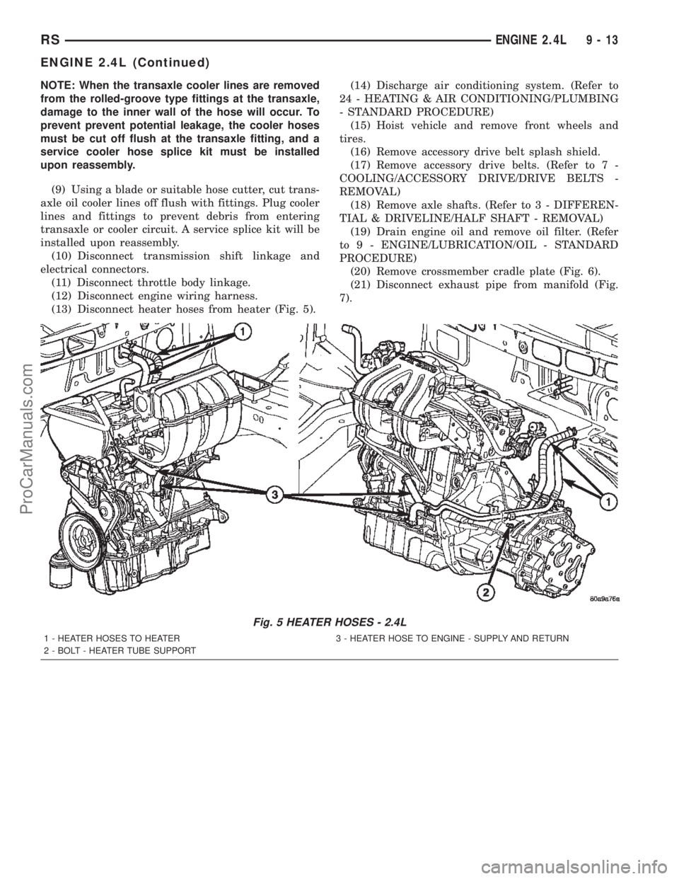
(13) Disconnect heater hoses from heater (Fig. 5).(14) Discharge air conditioning system. (Refer to
24 - HEATING & AIR CONDITIONING/PLUMBING
- STANDARD PROCEDURE)
(15) Hoist vehicle and remove front wheels and
tires.
(16) Remove accessory drive belt splash shield.
(17) Remove accessory drive belts. (Refer to 7 -
COOLING/ACCESSORY DRIVE/DRIVE BELTS -
REMOVAL)
(18) Remove axle shafts. (Refer to 3 - DIFFEREN-
TIAL & DRIVELINE/HALF SHAFT - REMOVAL)
(19) Drain engine oil and remove oil filter. (Refer
to 9 - ENGINE/LUBRICATION/OIL - STANDARD
PROCEDURE)
(20) Remove crossmember cradle plate (Fig. 6).
(21) Disconnect exhaust pipe from manifold (Fig.
7).
Fig. 5 HEATER HOSES - 2.4L
1 - HEATER HOSES TO HEATER 3 - HEATER HOSE TO ENGINE - SUPPLY AND RETURN
2 - BOLT - HEATER TUBE SUPPORT
RSENGINE 2.4L9-13
ENGINE 2.4L (Continued)
ProCarManuals.com
Page 1226 of 2399
Possible indications of the cylinder head gasket
leaking between adjacent cylinders are:
²Loss of engine power
²Engine misfiring
²Poor fuel economy
Possible indications of the cylinder head gasket
leaking between a cylinder and an adjacent water
jacket are:
²Engine overheating
²Loss of coolant
²Excessive steam (white smoke) emitting from
exhaust
²Coolant foaming
CYLINDER-TO-CYLINDER LEAKAGE TEST
To determine if an engine cylinder head gasket is
leaking between adjacent cylinders, follow the proce-
dures in Cylinder Compression Pressure Test (Refer
to 9 - ENGINE - DIAGNOSIS AND TESTING). An
engine cylinder head gasket leaking between adja-
cent cylinders will result in approximately a 50±70%
reduction in compression pressure.
CYLINDER-TO-WATER JACKET LEAKAGE TEST
WARNING: USE EXTREME CAUTION WHEN THE
ENGINE IS OPERATING WITH COOLANT PRES-
SURE CAP REMOVED.VISUAL TEST METHOD
With the engine cool, remove the coolant pressure
cap. Start the engine and allow it to warm up until
thermostat opens.
If a large combustion/compression pressure leak
exists, bubbles will be visible in the coolant.
COOLING SYSTEM TESTER METHOD
WARNING: WITH COOLING SYSTEM TESTER IN
PLACE, PRESSURE WILL BUILD UP FAST. EXCES-
SIVE PRESSURE BUILT UP, BY CONTINUOUS
ENGINE OPERATION, MUST BE RELEASED TO A
SAFE PRESSURE POINT. NEVER PERMIT PRES-
SURE TO EXCEED 138 kPa (20 psi).
Install Cooling System Tester 7700 or equivalent to
pressure cap neck. Start the engine and observe the
tester's pressure gauge. If gauge pulsates with every
power stroke of a cylinder a combustion pressure
leak is evident.
CHEMICAL TEST METHOD
Combustion leaks into the cooling system can also
be checked by using Bloc-Chek Kit C-3685-A or
equivalent. Perform test following the procedures
supplied with the tool kit.
REMOVAL - CYLINDER HEAD
(1) Perform fuel system pressure release procedure
before attempting any repairs.(Refer to 14 -
FUEL SYSTEM/FUEL DELIVERY - SPECIFICA-
TIONS)
(2) Disconnect battery negative cable.
(3) Drain cooling system. (Refer to 7 - COOLING -
STANDARD PROCEDURE)
(4) Remove air filter housing and inlet tube.
(5) Remove upper intake manifold. (Refer to 9 -
ENGINE/MANIFOLDS/INTAKE MANIFOLD -
REMOVAL)
(6) Remove heater tube support bracket from cyl-
inder head.
(7) Disconnect radiator upper and heater supply
hoses from intake manifold water outlet connections.
(8) Remove accessory drive belts. (Refer to 7 -
COOLING/ACCESSORY DRIVE/DRIVE BELTS -
REMOVAL)
(9) Raise vehicle and remove exhaust pipe from
manifold.
(10) Remove power steering pump reservoir and
line support bracket from lower intake manifold and
set aside. Do not disconnect lines.
(11) Remove ignition coil and wires from engine.
(12) Disconnect cam sensor and fuel injector wir-
ing connectors.
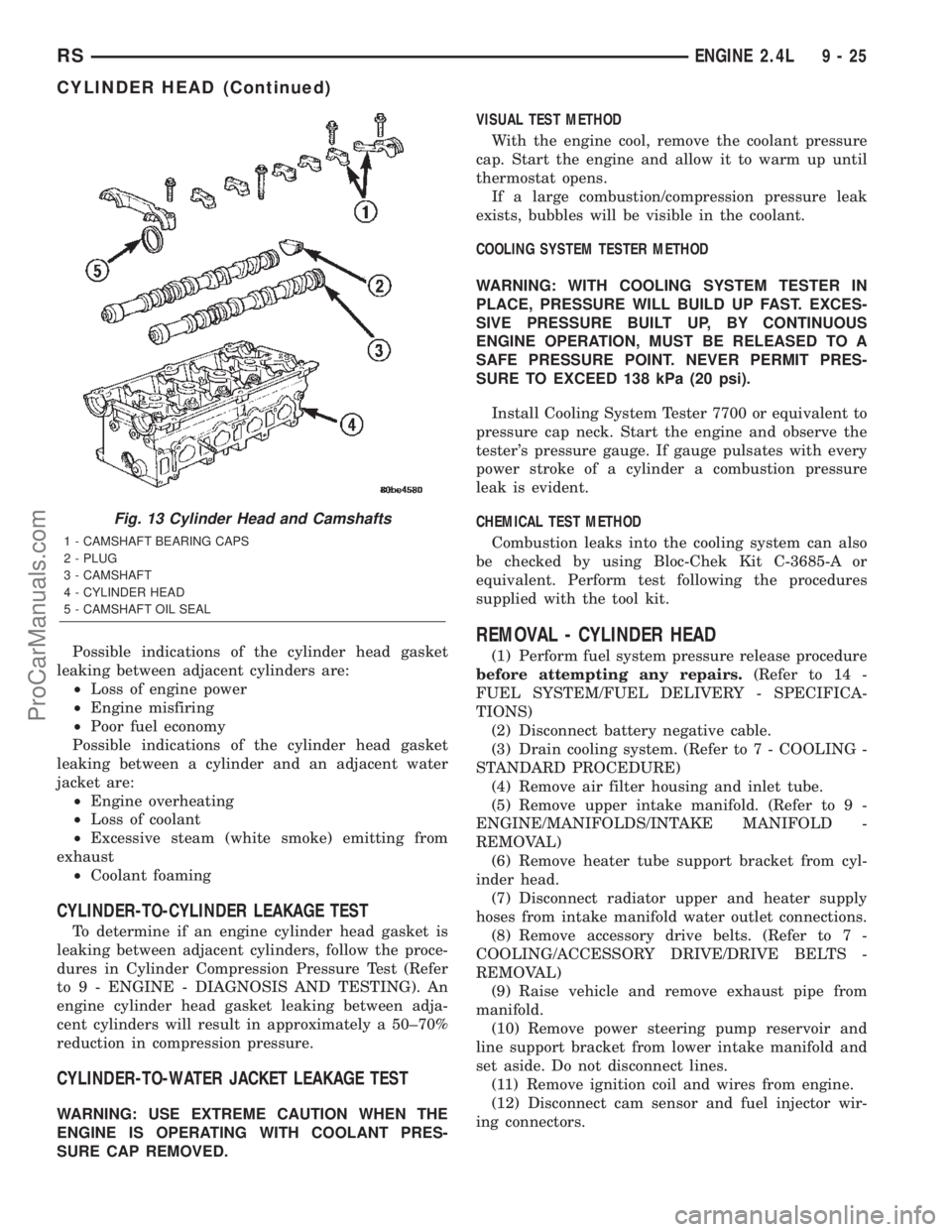
Fig. 13 Cylinder Head and Camshafts
1 - CAMSHAFT BEARING CAPS
2 - PLUG
3 - CAMSHAFT
4 - CYLINDER HEAD
5 - CAMSHAFT OIL SEAL
RSENGINE 2.4L9-25
CYLINDER HEAD (Continued)
ProCarManuals.com
Page 1288 of 2399
REMOVAL - ENGINE ASSEMBLY
(1) Perform fuel pressure release procedure (Refer
to 14 - FUEL SYSTEM/FUEL DELIVERY - STAN-
DARD PROCEDURE).
(2) Disconnect negative battery cable.
(3) Remove air cleaner and hoses.
(4) Disconnect the fuel line from fuel rail (Refer to
14 - FUEL SYSTEM/FUEL DELIVERY/QUICK
CONNECT FITTING - STANDARD PROCEDURE).
(5) Remove the wiper module (Refer to 8 - ELEC-
TRICAL/WIPERS/WASHERS/WIPER MODULE -
REMOVAL).
(6) Block off heater hoses to the rear heater sys-
tem using pinch-off pliers (if equipped).
(7) Drain the cooling system (Refer to 7 - COOL-
ING - STANDARD PROCEDURE).
(8) Disconnect the heater hoses.
(9) Remove the radiator upper support crossmem-
ber (Refer to 23 - BODY/EXTERIOR/GRILLE OPEN-
ING REINFORCEMENT - REMOVAL).
(10) Remove the radiator fans (Refer to 7 - COOL-
ING/ENGINE/RADIATOR FAN - REMOVAL).
(11) Disconnect the throttle cables from the throt-
tle body.
(12) Disconnect the MAP, IAC, and TPS electrical
connectors.
(13) Disconnect the EGR transducer electrical con-
nector (if equipped).
(14) Disconnect the vacuum hoses from throttle
body.
(15) Disconnect the brake booster and speed con-
trol vacuum hoses.
(16) Disengage wire harness clip from the right
side engine mount.
(17) Remove the power steering reservoir from
mounting position and set aside.Do notdisconnect
hose.
(18) Disconnect ground strap from rear of cylinder
head.
(19) Disconnect engine coolant temperature (ECT)
sensor and ignition coil electrical connectors.
(20) Disconnect the fuel injector electrical harness
connector and disengage clip from support bracket.
(21) Disconnect camshaft and crankshaft position
sensor electrical connectors.
(22) Evacuate air conditioning system. Refer to 24
- HEATING & AIR CONDITIONING.
(23) Disconnect A/C compressor electrical connec-
tor.(24) Disconnect the A/C lines from compressor.
Cover and seal all openings of hoses and compressor.
(25) Remove the radiator upper hose.
(26) Disengage electrical harness clip at transaxle
dipstick tube.
(27) Remove transaxle dipstick tube. Seal opening
using a suitable plug.
NOTE: When the transaxle cooler lines are removed
from the rolled-groove type fittings at the transaxle,
damage to the inner wall of the hose will occur. To
prevent prevent potential leakage, the cooler hoses
must be cut off flush at the transaxle fitting, and a
service cooler hose splice kit must be installed
upon reassembly.
(28) Using a blade or suitable hose cutter, cut
transaxle oil cooler lines off flush with fittings. Plug
cooler lines and fittings to prevent debris from enter-
ing transaxle or cooler circuit. A service splice kit will
be installed upon reassembly.
(29) Disconnect transaxle shift linkage and electri-
cal connectors.
(30) Raise vehicle on hoist and drain the engine
oil.
(31) Remove the axle shafts. (Refer to 3 - DIFFER-
ENTIAL & DRIVELINE/HALF SHAFT - REMOVAL)
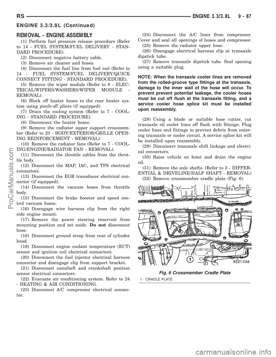
(32) Remove crossmember cradle plate (Fig. 6).
Fig. 6 Crossmember Cradle Plate
1 - CRADLE PLATE
RSENGINE 3.3/3.8L9-87
ENGINE 3.3/3.8L (Continued)
ProCarManuals.com
Page 1301 of 2399
INSTALLATION
(1) Install air box into vehicle and onto the locat-
ing pin.
(2) Install bolt to hold air box to the upper radia-
tor cross member.
(3) Install the inlet hose to the throttle body.
(4) Connect the inlet air temperature sensor (Fig.
16).
(5) Connect the negative battery cable.
CYLINDER HEAD
DESCRIPTION
The aluminum cylinder heads (Fig. 17) are
designed to create high flow combustion chambers to
improve performance, while minimizing the change
to the burn rate in the chamber. The cylinder head
incorporates the combustion chamber. Two valves
per-cylinder are used with inserted valve seats and
guides. A multi-layer steel (MLS) type gasket is used
between the cylinder head and engine block.
OPERATION
The cylinder head closes the combustion chamber,
allowing the pistons to compress the fuel/air mixture
for ignition. The valves are actuated by the lobe pro-
files on the camshaft to open and close at specified
duration to either allow clean air in the combustion
chamber or the exhaust gases out; depending on the
stroke of the engine.
DIAGNOSIS AND TESTINGÐCYLINDER HEAD
GASKET
A cylinder head gasket leak can be located between
adjacent cylinders or between a cylinder and the
adjacent water jacket.
Possible indications of the cylinder head gasket
leaking between adjacent cylinders are:
²Loss of engine power
²Engine misfiring
²Poor fuel economy
Possible indications of the cylinder head gasket
leaking between a cylinder and an adjacent water
jacket are:
²Engine overheating
²Loss of coolant
²Excessive steam (white smoke) emitting from
exhaust
²Coolant foaming
CYLINDER-TO-CYLINDER LEAKAGE TEST
To determine if an engine cylinder head gasket is
leaking between adjacent cylinders, follow the proce-
dures in Cylinder Compression Pressure Test (Refer
to 9 - ENGINE - DIAGNOSIS AND TESTING). An
engine cylinder head gasket leaking between adja-
cent cylinders will result in approximately a 50±70%
reduction in compression pressure.
CYLINDER-TO-WATER JACKET LEAKAGE TEST
WARNING: USE EXTREME CAUTION WHEN THE
ENGINE IS OPERATING WITH COOLANT PRES-
SURE CAP REMOVED.
VISUAL TEST METHOD
With the engine cool, remove the coolant pressure
cap. Start the engine and allow it to warm up until
thermostat opens.
If a large combustion/compression pressure leak
exists, bubbles will be visible in the coolant.
COOLING SYSTEM TESTER METHOD
WARNING: WITH COOLING SYSTEM TESTER IN
PLACE, PRESSURE WILL BUILD UP FAST. EXCES-
SIVE PRESSURE BUILT UP, BY CONTINUOUS
ENGINE OPERATION, MUST BE RELEASED TO A
SAFE PRESSURE POINT. NEVER PERMIT PRES-
SURE TO EXCEED 138 kPa (20 psi).
Install Cooling System Tester 7700 or equivalent to
pressure cap neck. Start the engine and observe the
tester's pressure gauge. If gauge pulsates with every
power stroke of a cylinder a combustion pressure
leak is evident.
CHEMICAL TEST METHOD
Combustion leaks into the cooling system can also
be checked by using Bloc-Chek Kit C-3685-A or
equivalent. Perform test following the procedures
supplied with the tool kit.
REMOVAL - CYLINDER HEAD
(1) Drain the cooling system. (Refer to 7 - COOL-
ING - STANDARD PROCEDURE)
(2) Disconnect negative cable from battery.
(3) Remove upper and lower intake manifolds.
(Refer to 9 - ENGINE/MANIFOLDS/INTAKE MANI-
FOLD - REMOVAL)
WARNING: INTAKE MANIFOLD GASKET IS MADE
OF VERY THIN METAL AND MAY CAUSE PER-
SONAL INJURY, HANDLE WITH CARE.
9 - 100 ENGINE 3.3/3.8LRS
AIR CLEANER HOUSING (Continued)
ProCarManuals.com
Page 1366 of 2399
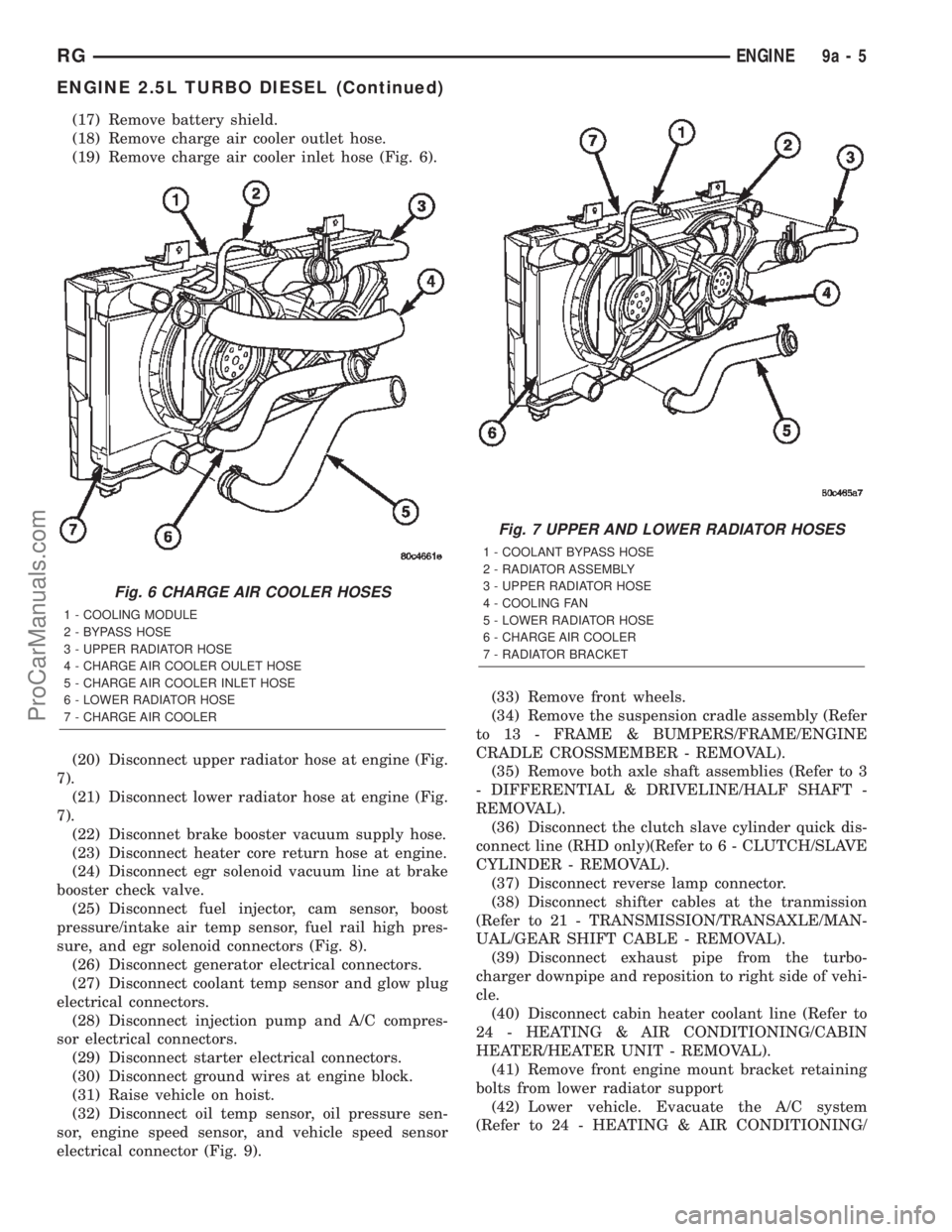
(17) Remove battery shield.
(18) Remove charge air cooler outlet hose.
(19) Remove charge air cooler inlet hose (Fig. 6).
(20) Disconnect upper radiator hose at engine (Fig.
7).
(21) Disconnect lower radiator hose at engine (Fig.
7).
(22) Disconnet brake booster vacuum supply hose.
(23) Disconnect heater core return hose at engine.
(24) Disconnect egr solenoid vacuum line at brake
booster check valve.
(25) Disconnect fuel injector, cam sensor, boost
pressure/intake air temp sensor, fuel rail high pres-
sure, and egr solenoid connectors (Fig. 8).
(26) Disconnect generator electrical connectors.
(27) Disconnect coolant temp sensor and glow plug
electrical connectors.
(28) Disconnect injection pump and A/C compres-
sor electrical connectors.
(29) Disconnect starter electrical connectors.
(30) Disconnect ground wires at engine block.
(31) Raise vehicle on hoist.
(32) Disconnect oil temp sensor, oil pressure sen-
sor, engine speed sensor, and vehicle speed sensor
electrical connector (Fig. 9).(33) Remove front wheels.
(34) Remove the suspension cradle assembly (Refer
to 13 - FRAME & BUMPERS/FRAME/ENGINE
CRADLE CROSSMEMBER - REMOVAL).
(35) Remove both axle shaft assemblies (Refer to 3
- DIFFERENTIAL & DRIVELINE/HALF SHAFT -
REMOVAL).
(36) Disconnect the clutch slave cylinder quick dis-
connect line (RHD only)(Refer to 6 - CLUTCH/SLAVE
CYLINDER - REMOVAL).
(37) Disconnect reverse lamp connector.
(38) Disconnect shifter cables at the tranmission
(Refer to 21 - TRANSMISSION/TRANSAXLE/MAN-
UAL/GEAR SHIFT CABLE - REMOVAL).
(39) Disconnect exhaust pipe from the turbo-
charger downpipe and reposition to right side of vehi-
cle.
(40) Disconnect cabin heater coolant line (Refer to
24 - HEATING & AIR CONDITIONING/CABIN
HEATER/HEATER UNIT - REMOVAL).
(41) Remove front engine mount bracket retaining
bolts from lower radiator support
(42) Lower vehicle. Evacuate the A/C system
(Refer to 24 - HEATING & AIR CONDITIONING/
Fig. 6 CHARGE AIR COOLER HOSES
1 - COOLING MODULE
2 - BYPASS HOSE
3 - UPPER RADIATOR HOSE
4 - CHARGE AIR COOLER OULET HOSE
5 - CHARGE AIR COOLER INLET HOSE
6 - LOWER RADIATOR HOSE
7 - CHARGE AIR COOLER
Fig. 7 UPPER AND LOWER RADIATOR HOSES
1 - COOLANT BYPASS HOSE
2 - RADIATOR ASSEMBLY
3 - UPPER RADIATOR HOSE
4 - COOLING FAN
5 - LOWER RADIATOR HOSE
6 - CHARGE AIR COOLER
7 - RADIATOR BRACKET
RGENGINE9a-5
ENGINE 2.5L TURBO DIESEL (Continued)
ProCarManuals.com