2002 CHRYSLER CARAVAN sensor
[x] Cancel search: sensorPage 2279 of 2399
INFRARED TEMPERATURE
SENSOR
DESCRIPTION
The rear infrared temperature sensor consists of
an infrared transducer that is concealed behind the
lens of the rear heater-A/C control in the headliner.
This sensor is used only on models equipped with the
optional Automatic Temperature Control (ATC) heat-
ing and air conditioning system. The rear infrared
temperature sensor is integral to the rear heater-A/C
control. The infrared sensor cannot be adjusted or
repaired and, if faulty or damaged, the rear heater-
A/C control unit must be replaced.
OPERATION
The rear infrared temperature sensor provides an
independent measurement input to the Automatic
Temperature Control (ATC) heater-A/C control mod-
ule that indicates the surface temperature of the rear
seat occupants. By using a surface temperature mea-
surement, rather than an air temperature measure-
ment, the ATC system is able to adjust itself to the
comfort level as perceived by the occupant. This
allows the system to detect and compensate for other
ambient conditions affecting comfort levels, such as
solar heat gain or evaporative heat loss. The ATC
system logic responds to the infrared sensor input by
calculating and adjusting the air flow temperature
and air flow rate needed to properly obtain and
maintain the selected comfort level temperatures for
the rear seat occupants. The ATC heater-A/C control
module continually monitors the infrared sensor cir-
cuit, and will store a Diagnostic Trouble Code (DTC)
for any problem it detects. This DTC information can
be retrieved and the infrared temperature sensor
diagnosed using a DRBIIItscan tool. Refer to the
appropriate diagnostic information.
MODE DOOR ACTUATOR
REMOVAL
(1) Disconnect and isolate the battery negative
cable.
(2) Remove the right quarter trim panel and right
D-pillar trim panel from the quarter inner panel.
(Refer to 23 - BODY/INTERIOR/QUARTER TRIM
PANEL - REMOVAL).
(3) Remove the two screws that secure the top of
the quarter trim panel attaching bracket to the quar-
ter inner panel.
(4) Remove the screw that secures the back of the
rear heater-A/C unit housing to the right D-pillar.(5) Remove the screw that secures the front of the
rear heater-A/C unit housing to the right quarter
inner panel.
(6) Carefully pull the top of the rear heater-A/C
unit housing away from the right quarter inner panel
far enough to reach between the rear heater-A/C unit
housing and the quarter inner panel to access the
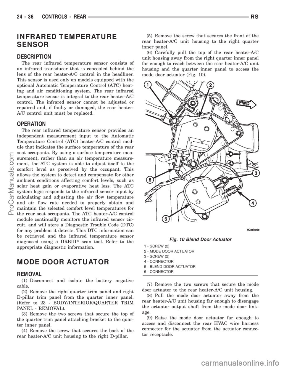
mode door actuator (Fig. 10).
(7) Remove the two screws that secure the mode
door actuator to the rear heater-A/C unit housing.
(8) Pull the mode door actuator away from the
rear heater-A/C unit housing far enough to disengage
the actuator output shaft from the mode door link-
age.
(9) Raise the mode door actuator far enough to
access and disconnect the rear HVAC wire harness
connector for the actuator from the actuator connec-
tor receptacle.
Fig. 10 Blend Door Actuator
1 - SCREW (2)
2 - MODE DOOR ACTUATOR
3 - SCREW (2)
4 - CONNECTOR
5 - BLEND DOOR ACTUATOR
6 - CONNECTOR
24 - 36 CONTROLS - REARRS
ProCarManuals.com
Page 2284 of 2399
or damaged, the instrument panel top cover must be
replaced.
²Demister Outlets- There are two side window
demisters that aid in defogging and defrosting the
front door windows. One demister outlet is located at
each outboard end of the instrument panel top pad,
near the belt line at the A-pillars. The demister out-
lets can be removed from the top pad individually for
service replacement.
²Instrument Panel Outlets- There are five
panel outlets in the instrument panel, one located
near each outboard end of the instrument panel fac-
ing the rear of the vehicle, and three located near the
top of the instrument panel center bezel. On models
with manual temperature control, all five of these
outlets are fully adjustable. On models with Auto-
matic Temperature Control (ATC), the center outlet
in the center bezel has fixed vanes because it also
houses the remote infrared temperature sensors for
the front seat positions. The outboard outlets can be
removed individually for service replacement. The
center bezel outlets are serviced as a gang of three
outlets and, on models with ATC, also includes the
infrared sensors.
²Front Door Rear Outlets- A fully adjustable
outlet located at the rear of each front door trim
panel supplies only cooled air to the intermediate
seat passengers. Air is supplied to these outlets from
the instrument panel through ducts in the doors that
use molded seals at the instrument panel to prevent
air leakage. The door ducts are integral to the front
door trim panels. These outlets also incorporate a red
reflector to improve the safety and visibility of an
opened front door to traffic approaching the vehicle
from the rear at night. These outlets can be removed
from the door trim panels for service replacement.
²Front Floor Outlets- There are two front floor
outlets, one located above each side of the floor panel
center tunnel below the instrument panel. These out-
lets are integral to the front heater-A/C unit distri-
bution housing.
²Rear Floor Outlets- Wide rear floor outlets
located under each front seat have integral, fixed
directional dividers to distribute heated air across
the floor for intermediate seat passengers. These out-
lets are integral to the floor distribution ducts routed
under the front floor carpet from an outlet nozzle on
the bottom of the front heater-A/C unit distribution
housing.
REMOVAL
REMOVAL - CENTER BEZEL OUTLETS
The three outlets located near the top of the
instrument panel center bezel are serviced only as a
set of all three outlets. If the vehicle is equipped withthe optional Automatic Temperature Control (ATC)
system, the center outlet of the three has fixed vanes
and also houses the remote front infrared tempera-
ture sensors.
WARNING: ON VEHICLES EQUIPPED WITH AIR-
BAGS, DISABLE THE AIRBAG SYSTEM BEFORE
ATTEMPTING ANY STEERING WHEEL, STEERING
COLUMN, OR INSTRUMENT PANEL COMPONENT
DIAGNOSIS OR SERVICE. DISCONNECT AND ISO-
LATE THE BATTERY NEGATIVE (GROUND) CABLE,
THEN WAIT TWO MINUTES FOR THE AIRBAG SYS-
TEM CAPACITOR TO DISCHARGE BEFORE PER-
FORMING FURTHER DIAGNOSIS OR SERVICE. THIS
IS THE ONLY SURE WAY TO DISABLE THE AIRBAG
SYSTEM. FAILURE TO TAKE THE PROPER PRE-
CAUTIONS COULD RESULT IN ACCIDENTAL AIR-
BAG DEPLOYMENT AND POSSIBLE PERSONAL
INJURY.
(1) Disconnect and isolate the battery negative
cable.
(2) Remove the center bezel from the instrument
panel. (Refer to 23 - BODY/INSTRUMENT PANEL/
INSTRUMENT PANEL CENTER BEZEL - REMOV-
AL).
(3) Place the center bezel face down on a suitable
work surface. Be certain to take the proper precau-
tions to protect the face of the center bezel from cos-
metic damage.
(4) If the vehicle is equipped with the optional
ATC system, disconnect the ATC remote infrared
temperature sensor jumper harness from the sensor
connector receptacle located on the bottom of the cen-
ter outlet housing (Fig. 3).
(5) Remove the three screws that secure the bot-
tom of the outlet housing to the center bezel.
(6) Roll the bottom of the outlet housing upwards
towards the top of the center bezel far enough to dis-
engage the retainer features on the top of the outlet
housing from their receptacles at the top of the cen-
ter bezel.
(7) Remove the center bezel outlets and housing
from the center bezel as a unit.
REMOVAL - DEMISTER OUTLET
(1) Using a trim stick or another suitable wide
flat-bladed tool, gently pry the outer perimeter of the
demister outlet away from the instrument panel top
pad until the snap features on the outlet are released
(Fig. 4).
(2) Remove the demister outlet from the demister
duct opening in the instrument panel top pad.
REMOVAL - FRONT DOOR REAR OUTLET
(1) Disconnect and isolate the battery negative
cable.
RSDISTRIBUTION - FRONT24-41
AIR OUTLETS (Continued)
ProCarManuals.com
Page 2286 of 2399
INSTALLATION
INSTALLATION - CENTER BEZEL OUTLETS
(1) Position the center bezel outlets and housing
onto the center bezel as a unit.
(2) Engage the retainer features on the top of the
outlet housing with their receptacles at the top of the
center bezel, then roll the bottom of the outlet hous-
ing downwards towards the center bezel.
(3) Install and tighten the three screws that secure
the bottom of the outlet housing to the center bezel.
Tighten the screws to 2 N´m (17 in. lbs.).
(4) If the vehicle is equipped with the optional
ATC system, reconnect the ATC remote infrared tem-
perature sensor jumper harness to the sensor connec-
tor receptacle located on the bottom of the center
outlet housing.
(5) Reinstall the center bezel onto the instrument
panel. (Refer to 23 - BODY/INSTRUMENT PANEL/
INSTRUMENT PANEL CENTER BEZEL - INSTAL-
LATION).
(6) Reconnect the battery negative cable.
INSTALLATION - DEMISTER OUTLET
(1) Position the demister outlet over the demister
duct opening in the instrument panel top pad.
(2) Using hand pressure, press the demister outlet
firmly and evenly into the instrument panel top pad
opening until the snap features on the outlet are
fully engaged.
INSTALLATION - FRONT DOOR REAR OUTLET
(1) Position the front door rear outlet through the
outside of the front door trim panel outlet opening.
(2) While keeping the outlet aligned with the door
duct opening behind the trim panel, use hand pres-
sure to press the outlet firmly and evenly through
the outside of the front door trim panel outlet open-
ing until the four latch features (two top and two bot-
tom) that secure the outlet to the inside of the
opening are fully engaged.
(3) Reinstall the trim panel onto the front door
inner panel. (Refer to 23 - BODY/DOOR - FRONT/
TRIM PANEL - INSTALLATION).
(4) Reconnect the battery negative cable.
INSTALLATION - INSTRUMENT PANEL OUTLET
(1) Position the instrument panel outlet into the
panel duct opening in the instrument panel top pad.
(2) Using hand pressure, press the instrument
panel outlet firmly and evenly into the instrument
panel top pad opening until the snap features on the
outlet are fully engaged.
BLOWER MOTOR
DESCRIPTION
The blower motor is a 12-volt, Direct Current (DC)
motor with a squirrel cage-type blower wheel that is
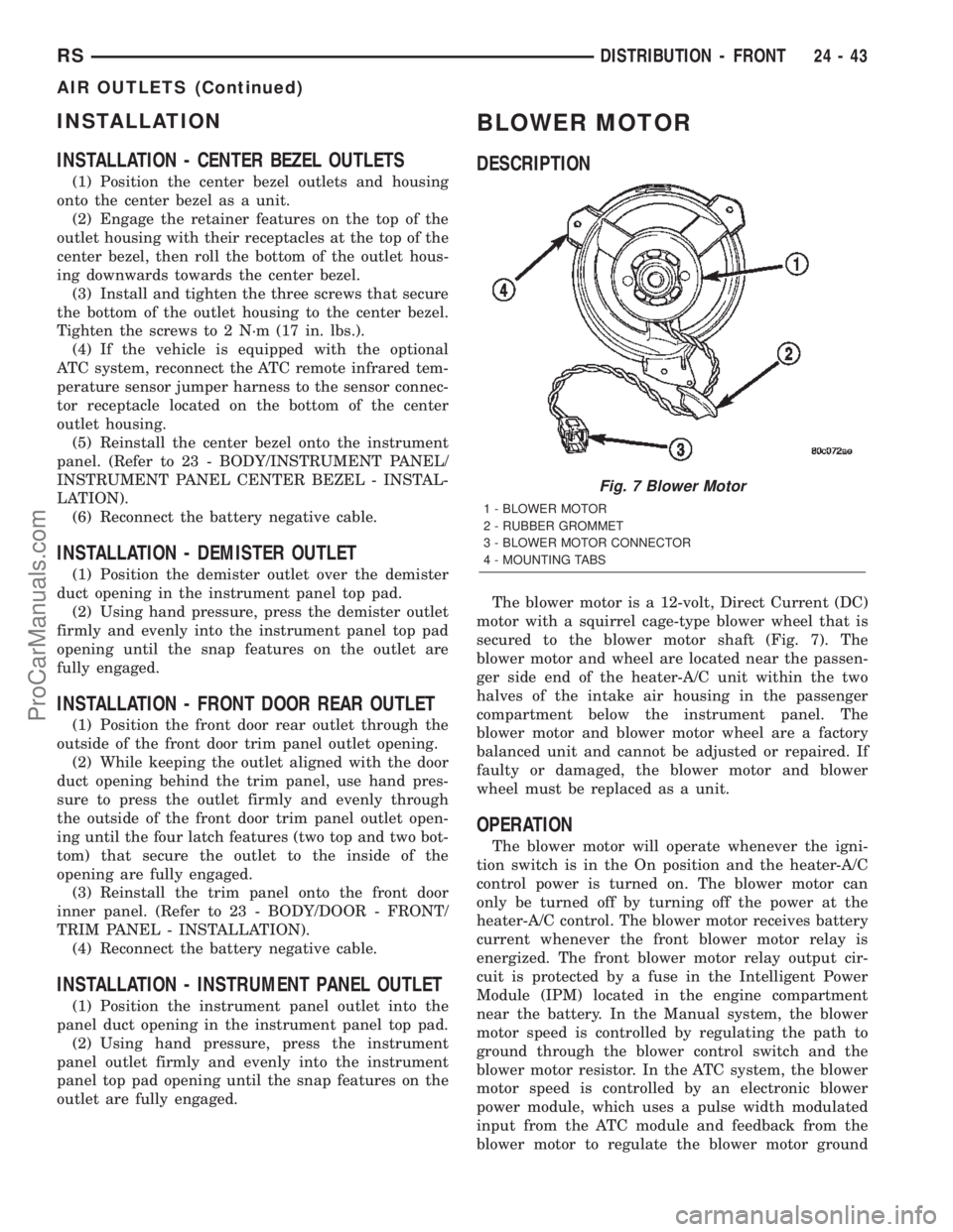
secured to the blower motor shaft (Fig. 7). The
blower motor and wheel are located near the passen-
ger side end of the heater-A/C unit within the two
halves of the intake air housing in the passenger
compartment below the instrument panel. The
blower motor and blower motor wheel are a factory
balanced unit and cannot be adjusted or repaired. If
faulty or damaged, the blower motor and blower
wheel must be replaced as a unit.
OPERATION
The blower motor will operate whenever the igni-
tion switch is in the On position and the heater-A/C
control power is turned on. The blower motor can
only be turned off by turning off the power at the
heater-A/C control. The blower motor receives battery
current whenever the front blower motor relay is
energized. The front blower motor relay output cir-
cuit is protected by a fuse in the Intelligent Power
Module (IPM) located in the engine compartment
near the battery. In the Manual system, the blower
motor speed is controlled by regulating the path to
ground through the blower control switch and the
blower motor resistor. In the ATC system, the blower
motor speed is controlled by an electronic blower
power module, which uses a pulse width modulated
input from the ATC module and feedback from the
blower motor to regulate the blower motor ground
Fig. 7 Blower Motor
1 - BLOWER MOTOR
2 - RUBBER GROMMET
3 - BLOWER MOTOR CONNECTOR
4 - MOUNTING TABS
RSDISTRIBUTION - FRONT24-43
AIR OUTLETS (Continued)
ProCarManuals.com
Page 2313 of 2399
(15) Carefully separate and remove the upper half
of the evaporator housing from the lower half. Be cer-
tain not to lose the rubber grommet for the HVAC
wire harness evaporator temperature sensor take
out. This grommet is located on the inboard side of
the flange around the expansion valve/evaporator
tube opening on the dash panel side of the unit,
where it is captured in a notched area between the
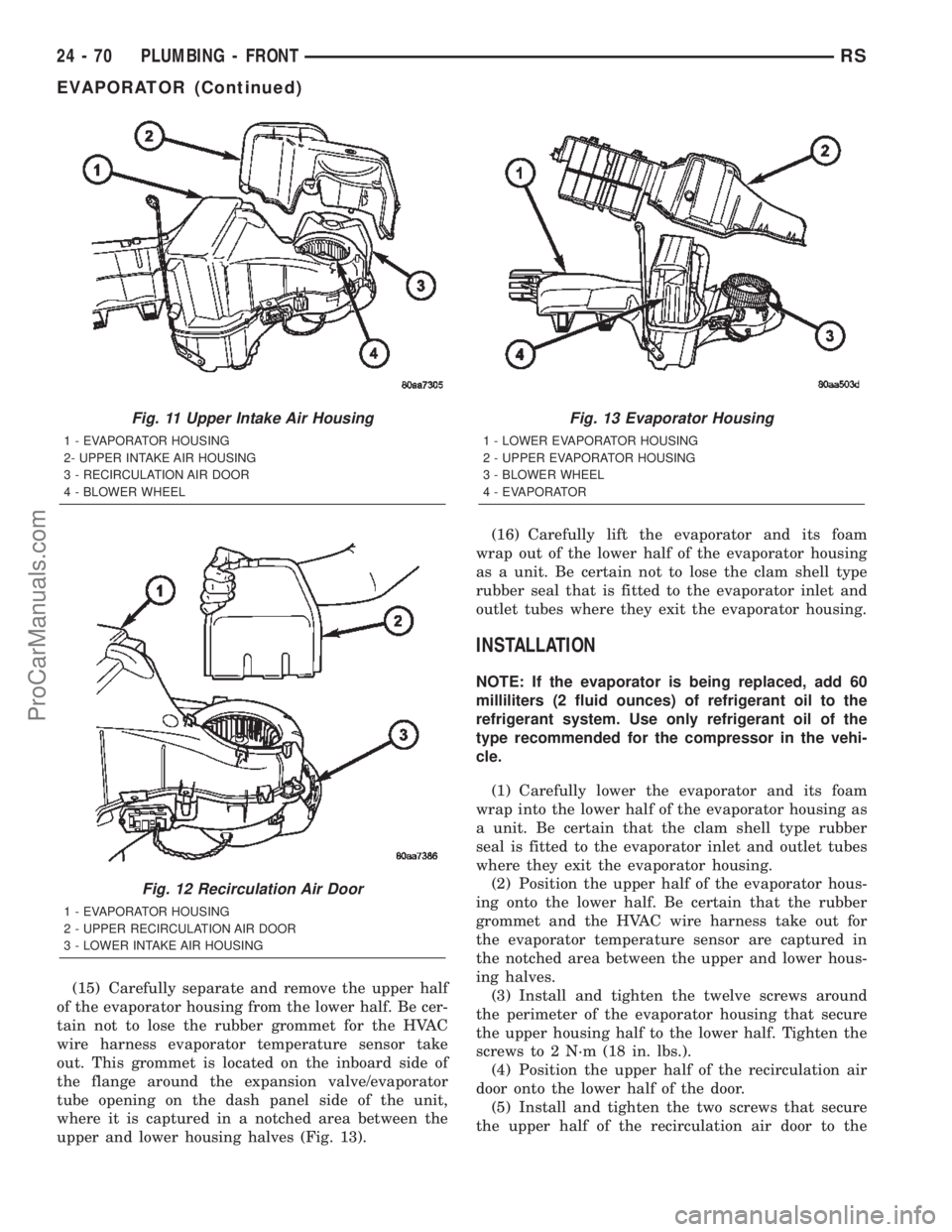
upper and lower housing halves (Fig. 13).(16) Carefully lift the evaporator and its foam
wrap out of the lower half of the evaporator housing
as a unit. Be certain not to lose the clam shell type
rubber seal that is fitted to the evaporator inlet and
outlet tubes where they exit the evaporator housing.
INSTALLATION
NOTE: If the evaporator is being replaced, add 60
milliliters (2 fluid ounces) of refrigerant oil to the
refrigerant system. Use only refrigerant oil of the
type recommended for the compressor in the vehi-
cle.
(1) Carefully lower the evaporator and its foam
wrap into the lower half of the evaporator housing as
a unit. Be certain that the clam shell type rubber
seal is fitted to the evaporator inlet and outlet tubes
where they exit the evaporator housing.
(2) Position the upper half of the evaporator hous-
ing onto the lower half. Be certain that the rubber
grommet and the HVAC wire harness take out for
the evaporator temperature sensor are captured in
the notched area between the upper and lower hous-
ing halves.
(3) Install and tighten the twelve screws around
the perimeter of the evaporator housing that secure
the upper housing half to the lower half. Tighten the
screws to 2 N´m (18 in. lbs.).
(4) Position the upper half of the recirculation air
door onto the lower half of the door.
(5) Install and tighten the two screws that secure
the upper half of the recirculation air door to the
Fig. 11 Upper Intake Air Housing
1 - EVAPORATOR HOUSING
2- UPPER INTAKE AIR HOUSING
3 - RECIRCULATION AIR DOOR
4 - BLOWER WHEEL
Fig. 12 Recirculation Air Door
1 - EVAPORATOR HOUSING
2 - UPPER RECIRCULATION AIR DOOR
3 - LOWER INTAKE AIR HOUSING
Fig. 13 Evaporator Housing
1 - LOWER EVAPORATOR HOUSING
2 - UPPER EVAPORATOR HOUSING
3 - BLOWER WHEEL
4 - EVAPORATOR
24 - 70 PLUMBING - FRONTRS
EVAPORATOR (Continued)
ProCarManuals.com
Page 2314 of 2399

lower half of the door. Tighten the screws to 2 N´m
(18 in. lbs.).
(6) Position the upper intake air housing onto the
top of the evaporator housing over the recirculation
air door and the blower wheel housing. Be certain
that the upper pivot of the recirculation air door is
captured in the pivot receptacle of the upper intake
air housing.
(7) Install and tighten the three screws that secure
the upper intake air housing to the top of the out-
board end of the evaporator housing. Be certain not
to miss the screw located just inside the inboard side
of the fresh air intake opening. Tighten the screws to
2 N´m (18 in. lbs.).
(8) Install and tighten the two screws that secure
the upper intake air housing to the lower intake air
housing. Tighten the screws to 2 N´m (18 in. lbs.).
(9) Engage the two hook formations on the bottom
of the distribution housing in the two receptacles on
the evaporator housing.
(10) Roll the top of the distribution housing up
into position against the evaporator housing.
(11) Install and tighten the three screws from the
dash panel side of the unit that secure the top of the
distribution housing to the inboard end of the evapo-
rator housing. Tighten the screws to 2 N´m (18 in.
lbs.).
(12) Engage the HVAC wire harness in the routing
clips molded into the outside of the HVAC housing
components.
(13) Reconnect the HVAC wire harness connector
for the blower motor with the motor connector recep-
tacle on the bottom of the outboard end of the evap-
orator housing.
(14) Reinstall the expansion valve onto the evapo-
rator inlet and outlet tube fittings. (Refer to 24 -
HEATING & AIR CONDITIONING/PLUMBING -
FRONT/EXPANSION VALVE - INSTALLATION).
(15) Install a new foam seal onto the HVAC hous-
ing seal flange around the fresh air inlet opening and
the expansion valve/evaporator tube opening on the
dash panel side of the unit.
(16) Reinstall the heater core tubes into the heater
core. (Refer to 24 - HEATING & AIR CONDITION-
ING/PLUMBING - FRONT/HEATER CORE -
INSTALLATION - HEATER CORE TUBES).
(17) Reinstall the HVAC unit housing into the
vehicle. (Refer to 24 - HEATING & AIR CONDI-
TIONING/DISTRIBUTION - FRONT/HVAC HOUS-
ING - INSTALLATION).
(18) Run the HVAC Control Actuator Calibration
procedure(Refer to 24 - HEATING & AIR CONDI-
TIONING - DIAGNOSIS AND TESTING)(Refer to 24
- HEATING & AIR CONDITIONING - DIAGNOSIS
AND TESTING).EXPANSION VALVE
DESCRIPTION
The front ªHº valve-type thermal expansion valve
(TXV) is located at the dash panel between the liquid
and suction lines, and the evaporator coil. The
assembly consists of an H-valve body and a thermal
sensor. High-pressure, low temperature liquid refrig-
erant from the liquid line passes through the expan-
sion valve orifice, converting it into a low-pressure,
low-temperature mixture of liquid and gas before it
enters the evaporator coil. The expansion valve is a
factory calibrated unit and cannot be adjusted or
repaired. If faulty or damaged, the expansion valve
must be replaced.
OPERATION
A mechanical sensor in the expansion valve control
head monitors the temperature and pressure of the
refrigerant leaving the evaporator coil through the
suction line, and adjusts the orifice size at the liquid
line to let the proper amount of refrigerant into the
evaporator coil to meet the vehicle cooling require-
ments. Controlling the refrigerant flow through the
evaporator ensures that none of the refrigerant leav-
ing the evaporator is still in a liquid state, which
could damage the compressor. The thermo sensor
measures refrigerant suction gas temperature which
is monitored by the a/c control assembly.
DIAGNOSIS AND TESTING - EXPANSION VALVE
WARNING: REFER TO THE APPLICABLE WARN-
INGS AND CAUTIONS FOR THIS SYSTEM BEFORE
PERFORMING THE FOLLOWING OPERATION.
(Refer to 24 - HEATING & AIR CONDITIONING/
PLUMBING - FRONT - WARNING - A/C PLUMBING)
and (Refer to 24 - HEATING & AIR CONDITIONING/
PLUMBING - FRONT - CAUTION - A/C PLUMBING).
NOTE: The expansion valve should only be tested
following testing of the compressor.
NOTE: Liquid CO is required to test the expansion
valve. This material is available from most welding
supply facilities. Liquid CO is also available from
companies which service and sell fire extinguish-
ers.
When testing the expansion valve, the work area
and the vehicle temperature must be 21É to 27É C
(70É to 85É F). To test the expansion valve:
(1) Connect a charging station or manifold gauge
set to the refrigerant system service ports. Verify the
refrigerant charge level.
RSPLUMBING - FRONT24-71
EVAPORATOR (Continued)
ProCarManuals.com
Page 2315 of 2399
(2) Close all doors, windows and vents to the pas-
senger compartment.
(3) Set the heater-air conditioner controls so that
the compressor is operating, the temperature control
is in the highest temperature position, the mode door
is directing the output to the floor outlets, and the
blower is operating at the highest speed setting.
(4) Start the engine and allow it to idle at 1000
rpm. After the engine has reached normal operating
temperature, allow the passenger compartment to
heat up. This will create the need for maximum
refrigerant flow into the evaporator.
(5) If the refrigerant charge is sufficient, the dis-
charge (high pressure) gauge should read 965 to 1655
kPa (140 to 240 psi). The suction (low pressure)
gauge should read 140 kPa to 207 kPa (20 psi to 30
psi). If OK, go to Step 6. If not OK, replace the faulty
expansion valve.
WARNING:
PROTECT THE SKIN AND EYES FROM EXPOSURE
TO LIQUID CO. PERSONAL INJURY CAN RESULT.
(6) If the suction (low pressure) gauge reads
within the specified range, freeze the expansion valve
control head for 30 seconds using liquid CO or
another suitable super-cold material.Do not spray
R-134a or R-12 refrigerant on the expansion
valve control head for this test.The suction (low
pressure) gauge reading should drop by 10 psi. If OK,
go to Step 7 If not OK, replace the faulty expansion
valve.
(7) Allow the expansion valve control head to thaw.
The suction (low pressure) gauge reading should sta-
bilize at 140 kPa to 240 kPa (20 psi to 30 psi). If not
OK, replace the faulty expansion valve.
(8) When expansion valve testing is complete, test
the overall air conditioner performance. (Refer to 24 -
HEATING & AIR CONDITIONING - DIAGNOSIS
AND TESTING - A/C PERFORMANCE TEST).
Remove all test equipment before returning the vehi-
cle to service.
REMOVAL
WARNING: REFER TO THE APPLICABLE WARN-
INGS AND CAUTIONS FOR THIS SYSTEM BEFORE
PERFORMING THE FOLLOWING OPERATION.
(Refer to 24 - HEATING & AIR CONDITIONING/
PLUMBING - FRONT - WARNING - A/C PLUMBING)
and (Refer to 24 - HEATING & AIR CONDITIONING/
PLUMBING - FRONT - CAUTION - A/C PLUMBING).
(1) Recover the refrigerant from the refrigerant
system. (Refer to 24 - HEATING & AIR CONDI-
TIONING/PLUMBING - FRONT/REFRIGERANT -STANDARD PROCEDURE - REFRIGERANT
RECOVERY).
(2) Disconnect and isolate the battery negative
cable.
(3) Remove the air cleaner housing from the right
side of the engine compartment.
(4) Disconnect the drain tube from the wiper mod-
ule drain on the right side of the engine compart-
ment.
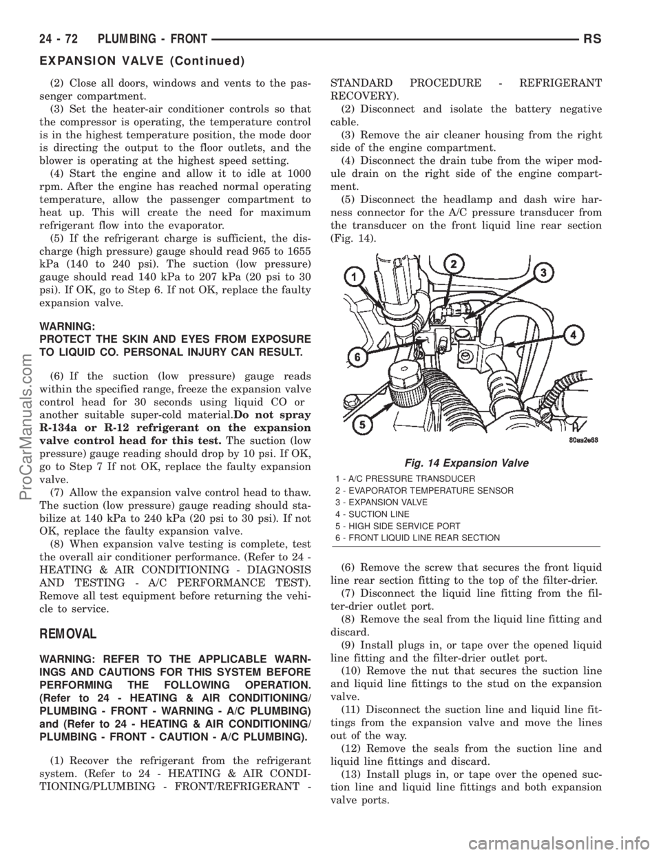
(5) Disconnect the headlamp and dash wire har-
ness connector for the A/C pressure transducer from
the transducer on the front liquid line rear section
(Fig. 14).
(6) Remove the screw that secures the front liquid
line rear section fitting to the top of the filter-drier.
(7) Disconnect the liquid line fitting from the fil-
ter-drier outlet port.
(8) Remove the seal from the liquid line fitting and
discard.
(9) Install plugs in, or tape over the opened liquid
line fitting and the filter-drier outlet port.
(10) Remove the nut that secures the suction line
and liquid line fittings to the stud on the expansion
valve.
(11) Disconnect the suction line and liquid line fit-
tings from the expansion valve and move the lines
out of the way.
(12) Remove the seals from the suction line and
liquid line fittings and discard.
(13) Install plugs in, or tape over the opened suc-
tion line and liquid line fittings and both expansion
valve ports.
Fig. 14 Expansion Valve
1 - A/C PRESSURE TRANSDUCER
2 - EVAPORATOR TEMPERATURE SENSOR
3 - EXPANSION VALVE
4 - SUCTION LINE
5 - HIGH SIDE SERVICE PORT
6 - FRONT LIQUID LINE REAR SECTION
24 - 72 PLUMBING - FRONTRS
EXPANSION VALVE (Continued)
ProCarManuals.com
Page 2316 of 2399
(14) Remove the two screws that secure the expan-
sion valve to the evaporator tube tapping plate.
(15) Disconnect the HVAC wire harness connector
for the evaporator temperature sensor from the sen-
sor on the top of the expansion valve.
(16) Remove the expansion valve from the evapo-
rator inlet and outlet tube fittings.
(17) Remove the seals from the evaporator inlet
and outlet tube fittings and discard.
(18) Install plugs in, or tape over the opened evap-
orator inlet and outlet tube fittings and both expan-
sion valve ports.
INSTALLATION
(1) Remove the tape or plugs from the evaporator
inlet and outlet tube fittings and both ports on the
back of the expansion valve.
(2) Lubricate new rubber O-ring seals with clean
refrigerant oil and install them on the evaporator
inlet and outlet tube fittings.
(3) Position the expansion valve onto the evapora-
tor inlet and outlet tube fittings.
(4) Install and tighten the two screws that secure
the expansion valve to the evaporator tube tapping
plate plate. Tighten the screws to 11 N´m (97 in.
lbs.).
(5) Reconnect the HVAC wire harness connector
for the evaporator temperature sensor to the sensor
connector receptacle on the top of the expansion
valve.
(6) Remove the tape or plugs from the front liquid
line rear section and suction line fittings for the
expansion valve and both ports on the front of the
expansion valve.
(7) Lubricate new rubber O-ring seals with clean
refrigerant oil and install them on the front liquid
line rear section and suction line fittings for the
expansion valve.
(8) Reconnect the liquid line and suction line fit-
tings to the expansion valve.
(9) Install and tighten the nut that secures the
suction line and liquid line fittings to the stud on the
expansion valve. Tighten the nut to 23 N´m (17 ft.
lbs.).
(10) Remove the tape or plugs from the liquid line
rear section fitting for the filter-drier and the filter-
drier outlet port.
(11) Lubricate a new rubber O-ring seal with clean
refrigerant oil and install it on the liquid line fitting.
(12) Reconnect the liquid line fitting to the filter-
drier outlet port on the top of the filter-drier.
(13) Install and tighten the screw that secures the
liquid line fitting to the filter-drier. Tighten the screw
to 2 N´m (18 in. lbs.).(14) Reconnect the headlamp and dash wire har-
ness connector for the A/C pressure transducer to the
transducer on the front liquid line rear section.
(15) Reconnect the drain tube to the wiper module
drain on the right side of the engine compartment.
(16) Reinstall the air cleaner housing into the
right side of the engine compartment.
(17) Reconnect the battery negative cable.
(18) Evacuate the refrigerant system. (Refer to 24
- HEATING & AIR CONDITIONING/PLUMBING -
FRONT/REFRIGERANT - STANDARD PROCE-
DURE - REFRIGERANT SYSTEM EVACUATE).
(19) Charge the refrigerant system. (Refer to 24 -
HEATING & AIR CONDITIONING/PLUMBING -
FRONT/REFRIGERANT - STANDARD PROCE-
DURE - REFRIGERANT SYSTEM CHARGE).
HEATER CORE
DESCRIPTION
The heater core is located in the distribution hous-
ing of the heater-A/C unit, under the instrument
panel. It is a heat exchanger made of rows of tubes
and fins. One end of the core is fitted with a molded
plastic tank that includes integral heater core inlet
and outlet ports. The removable heater core tubes
are held in place these ports by a sealing plate
secured with a screw to the heater core tank. This
removable heater core tube arrangement allows the
heater core to be serviced without removing the heat-
er-A/C unit housing from the vehicle. The heater core
cannot be repaired and, if faulty or damaged, it must
be replaced.
OPERATION
Engine coolant is circulated through heater hoses
to the heater core at all times. As the coolant flows
through the heater core, heat removed from the
engine is transferred to the heater core fins and
tubes. Air directed through the heater core picks up
the heat from the heater core fins. The blend air door
allows control of the heater output air temperature
by controlling how much of the air flowing through
the heater-A/C unit housing is directed through the
heater core.
RSPLUMBING - FRONT24-73
EXPANSION VALVE (Continued)
ProCarManuals.com
Page 2343 of 2399

OPERATION
A mechanical sensor in the expansion valve control
head monitors the temperature and pressure of the
refrigerant leaving the evaporator coil through the
suction line, and adjusts the orifice size at the liquid
line to let the proper amount of refrigerant into the
evaporator coil to meet the vehicle cooling require-
ments. Controlling the refrigerant flow through the
evaporator ensures that none of the refrigerant leav-
ing the evaporator is still in a liquid state, which
could damage the compressor.
DIAGNOSIS AND TESTING - EXPANSION VALVE
WARNING: REFER TO THE APPLICABLE WARN-
INGS AND CAUTIONS FOR THIS SYSTEM BEFORE
PERFORMING THE FOLLOWING OPERATION.
(Refer to 24 - HEATING & AIR CONDITIONING/
PLUMBING - FRONT - WARNING - A/C PLUMBING)
and (Refer to 24 - HEATING & AIR CONDITIONING/
PLUMBING - FRONT - CAUTION - A/C PLUMBING).
NOTE: The expansion valve should only be tested
following testing of the compressor.
NOTE: Liquid CO is required to test the expansion
valve. This material is available from most welding
supply facilities. Liquid CO is also available from
companies which service and sell fire extinguish-
ers.
When testing the expansion valve, the work area
and the vehicle temperature must be 21É to 27É C
(70É to 85É F). To test the expansion valve:
(1) Connect a charging station or manifold gauge
set to the refrigerant system service ports. Verify the
refrigerant charge level.
(2) Close all doors, windows and vents to the pas-
senger compartment.
(3) Set the heater-air conditioner controls so that
the compressor is operating, the temperature control
is in the highest temperature position, the mode door
is directing the output to the floor outlets, and the
blower is operating at the highest speed setting.
(4) Start the engine and allow it to idle at 1000
rpm. After the engine has reached normal operating
temperature, allow the passenger compartment to
heat up. This will create the need for maximum
refrigerant flow into the evaporator.
(5) If the refrigerant charge is sufficient, the dis-
charge (high pressure) gauge should read 965 to 1655
kPa (140 to 240 psi). The suction (low pressure)
gauge should read 140 kPa to 207 kPa (20 psi to 30
psi). If OK, go to Step 6. If not OK, replace the faulty
expansion valve.WARNING: PROTECT THE SKIN AND EYES FROM
EXPOSURE TO LIQUID CO. PERSONAL INJURY
CAN RESULT.
(6) If the suction (low pressure) gauge reads
within the specified range, freeze the expansion valve
control head for 30 seconds using liquid CO or
another suitable super-cold material.Do not spray
R-134a or R-12 refrigerant on the expansion
valve control head for this test.The suction (low
pressure) gauge reading should drop by 10 psi. If OK,
go to Step 7 If not OK, replace the faulty expansion
valve.
(7) Allow the expansion valve control head to thaw.
The suction (low pressure) gauge reading should sta-
bilize at 140 kPa to 240 kPa (20 psi to 30 psi). If not
OK, replace the faulty expansion valve.
(8) When expansion valve testing is complete, test
the overall air conditioner performance. (Refer to 24 -
HEATING & AIR CONDITIONING - DIAGNOSIS
AND TESTING - A/C PERFORMANCE TEST).
Remove all test equipment before returning the vehi-
cle to service.
REMOVAL
WARNING: REFER TO THE APPLICABLE WARN-
INGS AND CAUTIONS FOR THIS SYSTEM BEFORE
PERFORMING THE FOLLOWING OPERATION.
(Refer to 24 - HEATING & AIR CONDITIONING/
PLUMBING - FRONT - WARNING - A/C PLUMBING),
(Refer to 24 - HEATING & AIR CONDITIONING/
PLUMBING - FRONT - CAUTION - A/C PLUMBING),
and (Refer to 24 - HEATING & AIR CONDITIONING/
PLUMBING - FRONT - WARNING - HEATER PLUMB-
ING).
(1) Remove the rear heater-A/C unit housing from
the vehicle. (Refer to 24 - HEATING & AIR CONDI-
TIONING/DISTRIBUTION - REAR/REAR HEATER-
A/C HOUSING - REMOVAL).
(2) Carefully remove the foam insulator wrap from
the rear expansion valve.
(3) Remove the rear evaporator line extension from
the expansion valve. (Refer to 24 - HEATING & AIR
CONDITIONING/PLUMBING - REAR/EVAPORA-
TOR - REMOVAL - EVAPORATOR LINE EXTEN-
SION).
(4) Remove the two screws that secure the expan-
sion valve to the evaporator tube sealing plate.
(5) Remove the expansion valve from the evapora-
tor tubes.
(6) Remove the seals from the evaporator tube fit-
tings and discard.
(7) Install plugs in, or tape over the opened evap-
orator tube fittings and both expansion valve ports.
24 - 100 PLUMBING - REARRS
EXPANSION VALVE (Continued)
ProCarManuals.com