2002 CHRYSLER CARAVAN sensor
[x] Cancel search: sensorPage 1848 of 2399
TRANSMISSION CONTROL
RELAY
DESCRIPTION
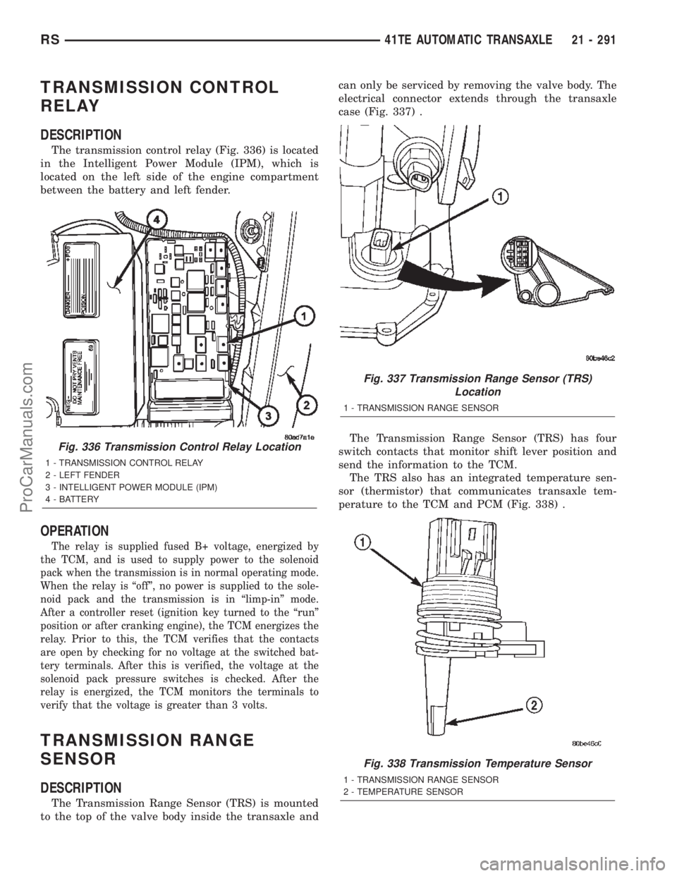
The transmission control relay (Fig. 336) is located
in the Intelligent Power Module (IPM), which is
located on the left side of the engine compartment
between the battery and left fender.
OPERATION
The relay is supplied fused B+ voltage, energized by
the TCM, and is used to supply power to the solenoid
pack when the transmission is in normal operating mode.
When the relay is ªoffº, no power is supplied to the sole-
noid pack and the transmission is in ªlimp-inº mode.
After a controller reset (ignition key turned to the ªrunº
position or after cranking engine), the TCM energizes the
relay. Prior to this, the TCM verifies that the contacts
are open by checking for no voltage at the switched bat-
tery terminals. After this is verified, the voltage at the
solenoid pack pressure switches is checked. After the
relay is energized, the TCM monitors the terminals to
verify that the voltage is greater than 3 volts.
TRANSMISSION RANGE
SENSOR
DESCRIPTION
The Transmission Range Sensor (TRS) is mounted
to the top of the valve body inside the transaxle andcan only be serviced by removing the valve body. The
electrical connector extends through the transaxle
case (Fig. 337) .
The Transmission Range Sensor (TRS) has four
switch contacts that monitor shift lever position and
send the information to the TCM.
The TRS also has an integrated temperature sen-
sor (thermistor) that communicates transaxle tem-
perature to the TCM and PCM (Fig. 338) .
Fig. 336 Transmission Control Relay Location
1 - TRANSMISSION CONTROL RELAY
2 - LEFT FENDER
3 - INTELLIGENT POWER MODULE (IPM)
4 - BATTERY
Fig. 337 Transmission Range Sensor (TRS)
Location
1 - TRANSMISSION RANGE SENSOR
Fig. 338 Transmission Temperature Sensor
1 - TRANSMISSION RANGE SENSOR
2 - TEMPERATURE SENSOR
RS41TE AUTOMATIC TRANSAXLE21 - 291
ProCarManuals.com
Page 1849 of 2399
OPERATION
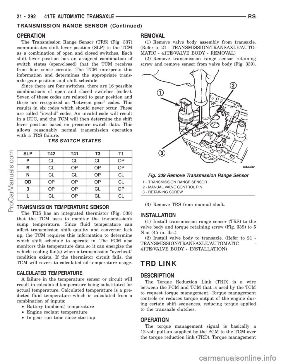
The Transmission Range Sensor (TRS) (Fig. 337)
communicates shift lever position (SLP) to the TCM
as a combination of open and closed switches. Each
shift lever position has an assigned combination of
switch states (open/closed) that the TCM receives
from four sense circuits. The TCM interprets this
information and determines the appropriate trans-
axle gear position and shift schedule.
Since there are four switches, there are 16 possible
combinations of open and closed switches (codes).
Seven of these codes are related to gear position and
three are recognized as ªbetween gearº codes. This
results in six codes which should never occur. These
are called ªinvalidº codes. An invalid code will result
in a DTC, and the TCM will then determine the shift
lever position based on pressure switch data. This
allows reasonably normal transmission operation
with a TRS failure.
TRS SWITCH STATES
SLP T42 T41 T3 T1
PCL CL CL OP
RCL OP OP OP
NCL CL OP CL
ODOP OP OP CL
3OP OP CL OP
LCL OP CL CL
TRANSMISSION TEMPERATURE SENSOR
The TRS has an integrated thermistor (Fig. 338)
that the TCM uses to monitor the transmission's
sump temperature. Since fluid temperature can
affect transmission shift quality and convertor lock
up, the TCM requires this information to determine
which shift schedule to operate in. The PCM also
monitors this temperature data so it can energize the
vehicle cooling fan(s) when a transmission ªoverheatº
condition exists. If the thermistor circuit fails, the
TCM will revert to calculated oil temperature usage.
CALCULATED TEMPERATURE
A failure in the temperature sensor or circuit will
result in calculated temperature being substituted for
actual temperature. Calculated temperature is a pre-
dicted fluid temperature which is calculated from a
combination of inputs:
²Battery (ambient) temperature
²Engine coolant temperature
²In-gear run time since start-up
REMOVAL
(1) Remove valve body assembly from transaxle.
(Refer to 21 - TRANSMISSION/TRANSAXLE/AUTO-
MATIC - 41TE/VALVE BODY - REMOVAL)
(2) Remove transmission range sensor retaining
screw and remove sensor from valve body (Fig. 339).
(3) Remove TRS from manual shaft.
INSTALLATION
(1) Install transmission range sensor (TRS) to the
valve body and torque retaining screw (Fig. 339) to 5
N´m (45 in. lbs.).
(2) Install valve body to transaxle. (Refer to 21 -
TRANSMISSION/TRANSAXLE/AUTOMATIC -
41TE/VALVE BODY - INSTALLATION)
TRD LINK
DESCRIPTION
The Torque Reduction Link (TRD) is a wire
between the PCM and TCM that is used by the TCM
to request torque management. Torque management
controls or reduces torque output of the engine dur-
ing certain shift sequences, reducing torque applied
to the transaxle clutches.
OPERATION
The torque management signal is basically a
12-volt pull-up supplied by the PCM to the TCM over
the torque reduction link (TRD). Torque management
Fig. 339 Remove Transmission Range Sensor
1 - TRANSMISSION RANGE SENSOR
2 - MANUAL VALVE CONTROL PIN
3 - RETAINING SCREW
21 - 292 41TE AUTOMATIC TRANSAXLERS
TRANSMISSION RANGE SENSOR (Continued)
ProCarManuals.com
Page 1854 of 2399

(9) Remove park rod rollers from guide bracket
and remove valve body from transaxle (Fig. 351) (Fig.
352).
CAUTION: The valve body manual shaft pilot may
distort and bind the manual valve if the valve body
is mishandled or dropped.
DISASSEMBLY
NOTE: If valve body assembly is being recondi-
tioned, the TCM Quick Learn Procedure must be
performed. (Refer to 8 - ELECTRICAL/ELECTRONIC
CONTROL MODULES/TRANSMISSION CONTROL
MODULE - STANDARD PROCEDURE)(1) Remove manual shaft seal (Fig. 353).
(2) Remove Transmission Range Sensor retaining
screw (Fig. 354).
Fig. 351 Push Park Rod Rollers from Guide Bracket
1 - PARK SPRAG ROLLERS
2 - SCREWDRIVER
3 - PARK SPRAG GUIDE BRACKET
Fig. 352 Valve Body Removal/Installation
1 - VALVE BODY
Fig. 353 Manual Shaft Seal
1 - SEAL
2 - MANUAL SHAFT
Fig. 354 Remove Transmission Range Sensor
1 - TRANSMISSION RANGE SENSOR
2 - MANUAL VALVE CONTROL PIN
3 - RETAINING SCREW
RS41TE AUTOMATIC TRANSAXLE21 - 297
VALVE BODY (Continued)
ProCarManuals.com
Page 1855 of 2399
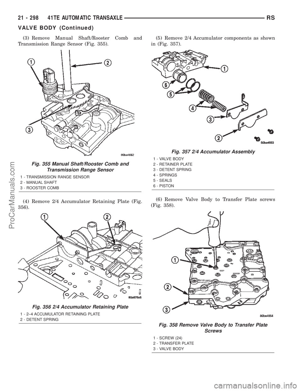
(3) Remove Manual Shaft/Rooster Comb and
Transmission Range Sensor (Fig. 355).
(4) Remove 2/4 Accumulator Retaining Plate (Fig.
356).(5) Remove 2/4 Accumulator components as shown
in (Fig. 357).
(6) Remove Valve Body to Transfer Plate screws
(Fig. 358).
Fig. 355 Manual Shaft/Rooster Comb and
Transmission Range Sensor
1 - TRANSMISSION RANGE SENSOR
2 - MANUAL SHAFT
3 - ROOSTER COMB
Fig. 356 2/4 Accumulator Retaining Plate
1 - 2±4 ACCUMULATOR RETAINING PLATE
2 - DETENT SPRING
Fig. 357 2/4 Accumulator Assembly
1 - VALVE BODY
2 - RETAINER PLATE
3 - DETENT SPRING
4 - SPRINGS
5 - SEALS
6 - PISTON
Fig. 358 Remove Valve Body to Transfer Plate
Screws
1 - SCREW (24)
2 - TRANSFER PLATE
3 - VALVE BODY
21 - 298 41TE AUTOMATIC TRANSAXLERS
VALVE BODY (Continued)
ProCarManuals.com
Page 1863 of 2399
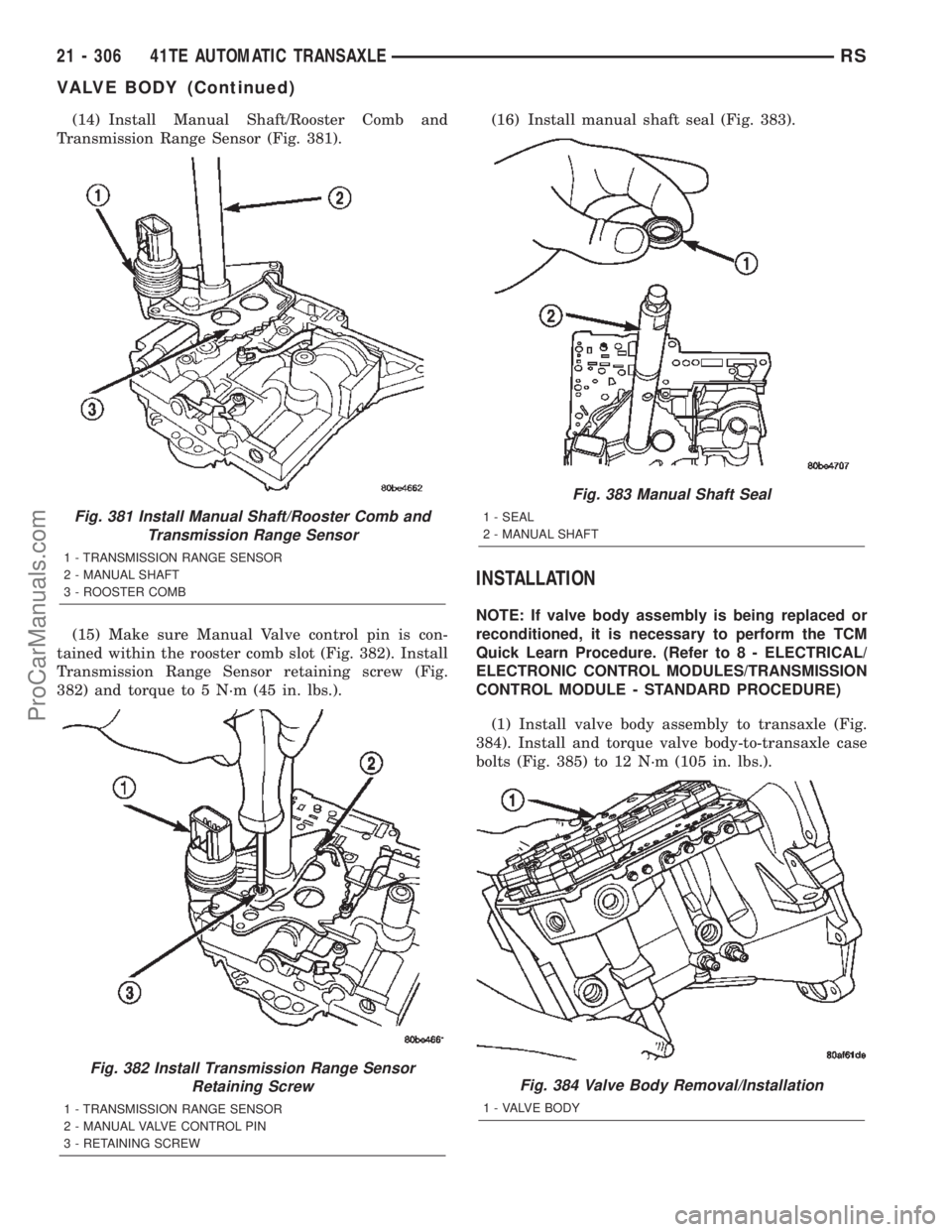
(14) Install Manual Shaft/Rooster Comb and
Transmission Range Sensor (Fig. 381).
(15) Make sure Manual Valve control pin is con-
tained within the rooster comb slot (Fig. 382). Install
Transmission Range Sensor retaining screw (Fig.
382) and torque to 5 N´m (45 in. lbs.).(16) Install manual shaft seal (Fig. 383).
INSTALLATION
NOTE: If valve body assembly is being replaced or
reconditioned, it is necessary to perform the TCM
Quick Learn Procedure. (Refer to 8 - ELECTRICAL/
ELECTRONIC CONTROL MODULES/TRANSMISSION
CONTROL MODULE - STANDARD PROCEDURE)
(1) Install valve body assembly to transaxle (Fig.
384). Install and torque valve body-to-transaxle case
bolts (Fig. 385) to 12 N´m (105 in. lbs.).
Fig. 381 Install Manual Shaft/Rooster Comb and
Transmission Range Sensor
1 - TRANSMISSION RANGE SENSOR
2 - MANUAL SHAFT
3 - ROOSTER COMB
Fig. 382 Install Transmission Range Sensor
Retaining Screw
1 - TRANSMISSION RANGE SENSOR
2 - MANUAL VALVE CONTROL PIN
3 - RETAINING SCREW
Fig. 383 Manual Shaft Seal
1 - SEAL
2 - MANUAL SHAFT
Fig. 384 Valve Body Removal/Installation
1 - VALVE BODY
21 - 306 41TE AUTOMATIC TRANSAXLERS
VALVE BODY (Continued)
ProCarManuals.com
Page 1864 of 2399
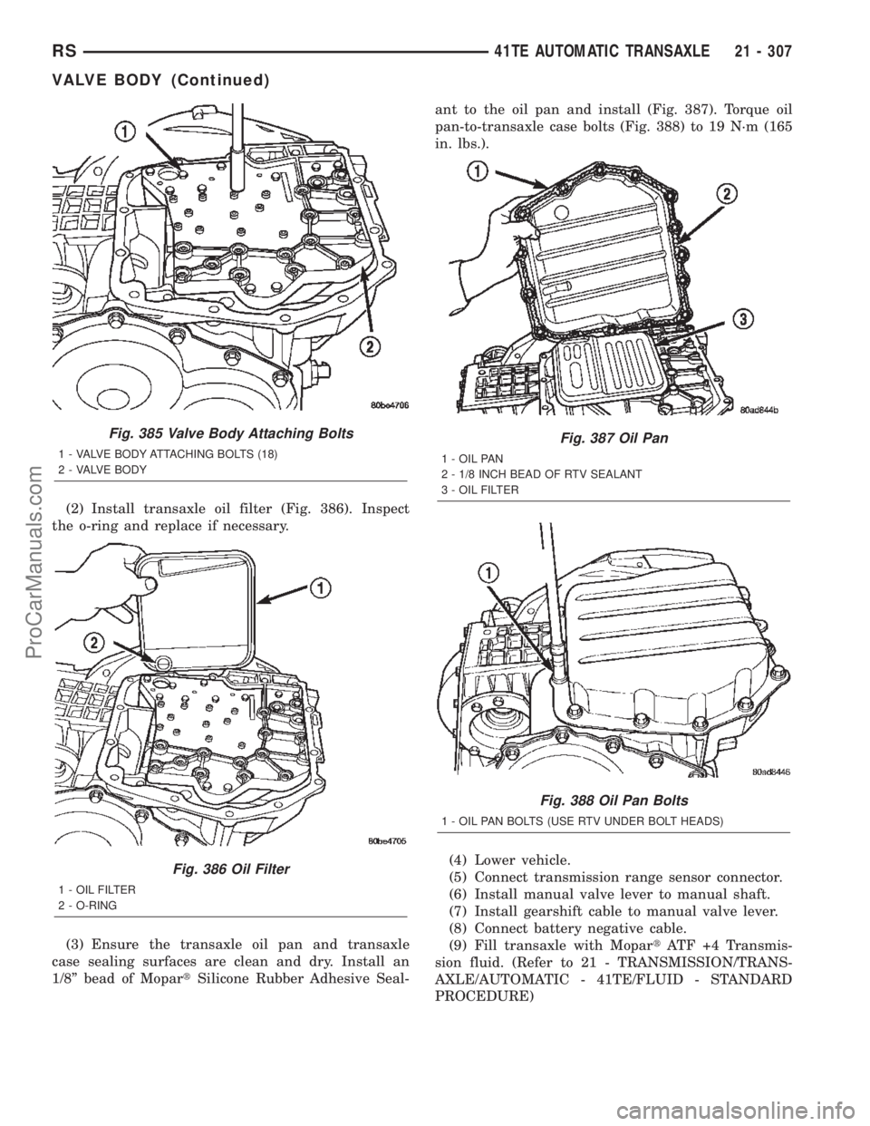
(2) Install transaxle oil filter (Fig. 386). Inspect
the o-ring and replace if necessary.
(3) Ensure the transaxle oil pan and transaxle
case sealing surfaces are clean and dry. Install an
1/8º bead of MopartSilicone Rubber Adhesive Seal-ant to the oil pan and install (Fig. 387). Torque oil
pan-to-transaxle case bolts (Fig. 388) to 19 N´m (165
in. lbs.).
(4) Lower vehicle.
(5) Connect transmission range sensor connector.
(6) Install manual valve lever to manual shaft.
(7) Install gearshift cable to manual valve lever.
(8) Connect battery negative cable.
(9) Fill transaxle with MopartATF +4 Transmis-
sion fluid. (Refer to 21 - TRANSMISSION/TRANS-
AXLE/AUTOMATIC - 41TE/FLUID - STANDARD
PROCEDURE)
Fig. 385 Valve Body Attaching Bolts
1 - VALVE BODY ATTACHING BOLTS (18)
2 - VALVE BODY
Fig. 386 Oil Filter
1 - OIL FILTER
2 - O-RING
Fig. 387 Oil Pan
1 - OIL PAN
2 - 1/8 INCH BEAD OF RTV SEALANT
3 - OIL FILTER
Fig. 388 Oil Pan Bolts
1 - OIL PAN BOLTS (USE RTV UNDER BOLT HEADS)
RS41TE AUTOMATIC TRANSAXLE21 - 307
VALVE BODY (Continued)
ProCarManuals.com
Page 1865 of 2399
T850 MANUAL TRANSAXLE
TABLE OF CONTENTS
page page
T850 MANUAL TRANSAXLE
DESCRIPTION........................308
OPERATION..........................311
DIAGNOSIS AND TESTING - COMMON
PROBLEM CAUSES...................318
REMOVAL............................318
DISASSEMBLY........................323
ASSEMBLY...........................329
INSTALLATION........................338
SPECIFICATIONS - T850 MANUAL
TRANSAXLE........................343
SPECIAL TOOLS - T850 TRANSAXLE.......345
AXLE SEALS
REMOVAL............................348
INSTALLATION........................348
BACK-UP LAMP SWITCH
REMOVAL............................349
INSTALLATION........................349
DIFFERENTIAL
DESCRIPTION........................349
OPERATION..........................349
DISASSEMBLY........................350
ASSEMBLY...........................353
ADJUSTMENTS
ADJUSTMENT - DIFFERENTIAL TURNING
TORQUE...........................356
ADJUSTMENT - DIFFERENTIAL SIDE GEAR
ENDPLAY..........................358
FLUID
STANDARD PROCEDURE
STANDARD PROCEDURE - FLUID LEVEL
CHECK............................358
STANDARD PROCEDURE - FLUID DRAIN
AND FILL...........................359
GEARSHIFT BOOT
REMOVAL............................359
INSTALLATION........................360GEARSHIFT CABLE - CROSSOVER
REMOVAL............................360
INSTALLATION........................363
ADJUSTMENTS
ADJUSTMENT.......................366
GEARSHIFT CABLE - SELECTOR
REMOVAL............................368
INSTALLATION........................371
GEARSHIFT KNOB
REMOVAL............................374
INSTALLATION........................374
GEARSHIFT MECHANISM
REMOVAL............................375
INSTALLATION........................377
INPUT SHAFT
DESCRIPTION........................380
DISASSEMBLY........................380
ASSEMBLY...........................383
INTERMEDIATE SHAFT
DESCRIPTION........................387
DISASSEMBLY........................388
ASSEMBLY...........................395
SHIFT COVER
DESCRIPTION........................401
SHIFT FORK AND SHAFT
DESCRIPTION........................402
SYNCHRONIZER
DESCRIPTION........................402
DISASSEMBLY........................402
CLEANING
CLEAN............................402
INSPECTION
INSPECT...........................402
ASSEMBLY...........................403
VEHICLE SPEED SENSOR
REMOVAL............................403
INSTALLATION........................403
T850 MANUAL TRANSAXLE
DESCRIPTION
The NV T850 5-speed transaxle (Fig. 1) is a con-
stant-mesh manual transaxle that is synchronized in
all gear ranges, including reverse.
The transaxle consists of three major sub-assem-
blies: the input shaft, intermediate shaft, and differ-ential assembly. The transaxle shift system consists
of a mechanical shift cover, rails, forks, and cables.
The unique design of this shift system provides a
higher mechanical advantage, resulting in less fric-
tion and lower shift cable loads for smoother, more
positive operation.
21 - 308 T850 MANUAL TRANSAXLERS
ProCarManuals.com
Page 1878 of 2399
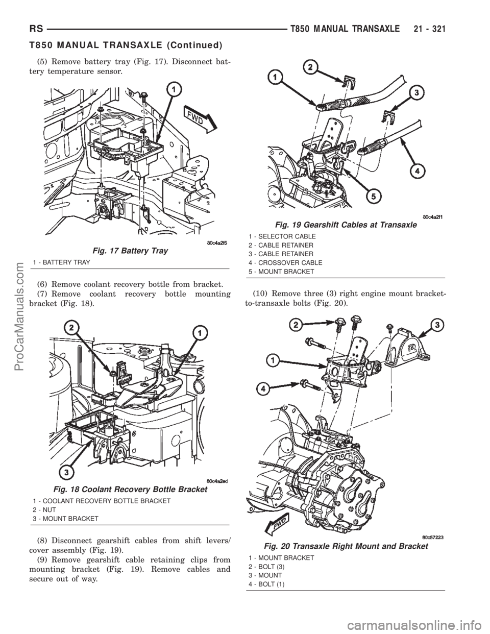
(5) Remove battery tray (Fig. 17). Disconnect bat-
tery temperature sensor.
(6) Remove coolant recovery bottle from bracket.
(7) Remove coolant recovery bottle mounting
bracket (Fig. 18).
(8) Disconnect gearshift cables from shift levers/
cover assembly (Fig. 19).
(9) Remove gearshift cable retaining clips from
mounting bracket (Fig. 19). Remove cables and
secure out of way.(10) Remove three (3) right engine mount bracket-
to-transaxle bolts (Fig. 20).
Fig. 17 Battery Tray
1 - BATTERY TRAY
Fig. 18 Coolant Recovery Bottle Bracket
1 - COOLANT RECOVERY BOTTLE BRACKET
2 - NUT
3 - MOUNT BRACKET
Fig. 19 Gearshift Cables at Transaxle
1 - SELECTOR CABLE
2 - CABLE RETAINER
3 - CABLE RETAINER
4 - CROSSOVER CABLE
5 - MOUNT BRACKET
Fig. 20 Transaxle Right Mount and Bracket
1 - MOUNT BRACKET
2 - BOLT (3)
3 - MOUNT
4 - BOLT (1)
RST850 MANUAL TRANSAXLE21 - 321
T850 MANUAL TRANSAXLE (Continued)
ProCarManuals.com