2002 CHRYSLER CARAVAN battery
[x] Cancel search: batteryPage 1301 of 2399
INSTALLATION
(1) Install air box into vehicle and onto the locat-
ing pin.
(2) Install bolt to hold air box to the upper radia-
tor cross member.
(3) Install the inlet hose to the throttle body.
(4) Connect the inlet air temperature sensor (Fig.
16).
(5) Connect the negative battery cable.
CYLINDER HEAD
DESCRIPTION
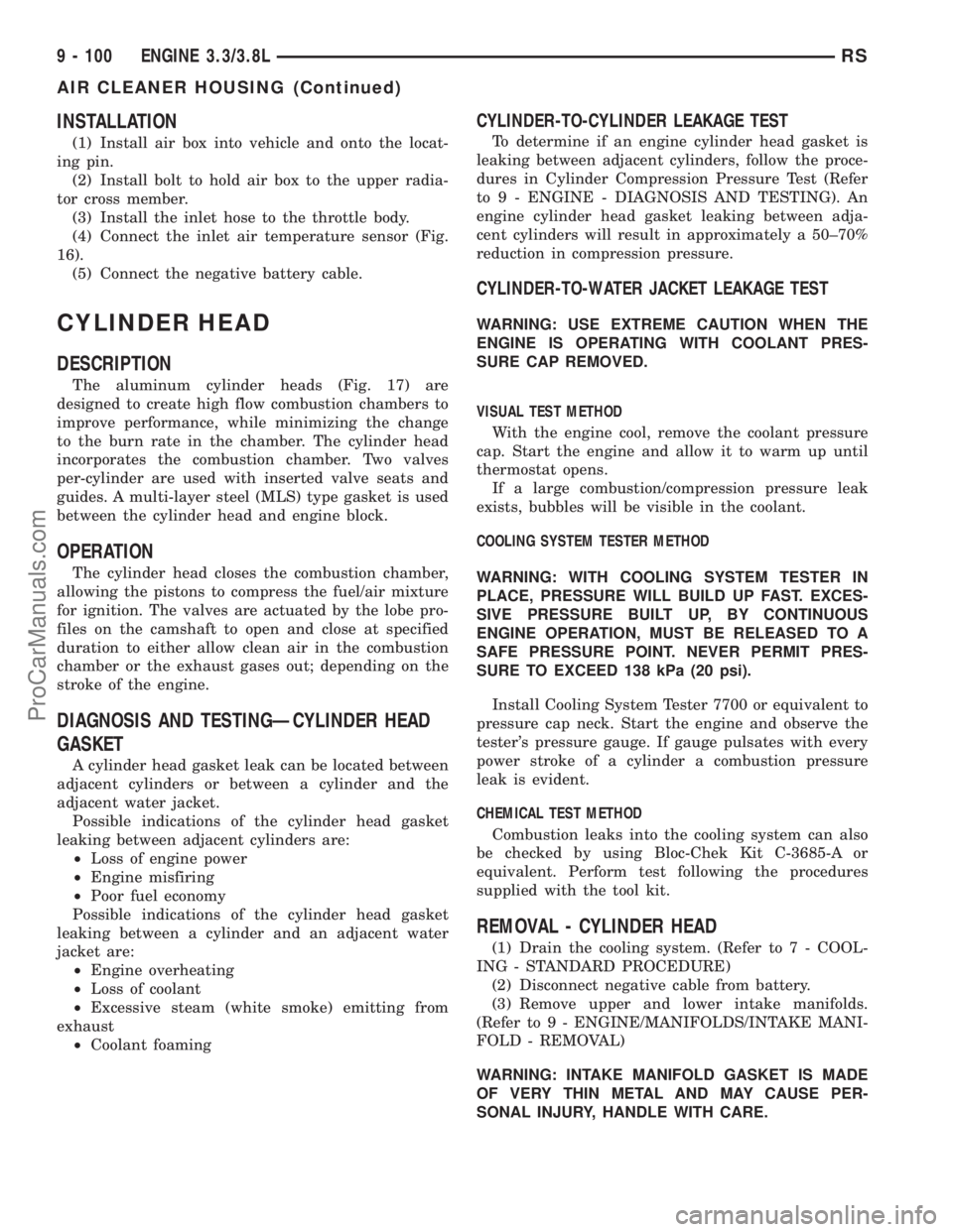
The aluminum cylinder heads (Fig. 17) are
designed to create high flow combustion chambers to
improve performance, while minimizing the change
to the burn rate in the chamber. The cylinder head
incorporates the combustion chamber. Two valves
per-cylinder are used with inserted valve seats and
guides. A multi-layer steel (MLS) type gasket is used
between the cylinder head and engine block.
OPERATION
The cylinder head closes the combustion chamber,
allowing the pistons to compress the fuel/air mixture
for ignition. The valves are actuated by the lobe pro-
files on the camshaft to open and close at specified
duration to either allow clean air in the combustion
chamber or the exhaust gases out; depending on the
stroke of the engine.
DIAGNOSIS AND TESTINGÐCYLINDER HEAD
GASKET
A cylinder head gasket leak can be located between
adjacent cylinders or between a cylinder and the
adjacent water jacket.
Possible indications of the cylinder head gasket
leaking between adjacent cylinders are:
²Loss of engine power
²Engine misfiring
²Poor fuel economy
Possible indications of the cylinder head gasket
leaking between a cylinder and an adjacent water
jacket are:
²Engine overheating
²Loss of coolant
²Excessive steam (white smoke) emitting from
exhaust
²Coolant foaming
CYLINDER-TO-CYLINDER LEAKAGE TEST
To determine if an engine cylinder head gasket is
leaking between adjacent cylinders, follow the proce-
dures in Cylinder Compression Pressure Test (Refer
to 9 - ENGINE - DIAGNOSIS AND TESTING). An
engine cylinder head gasket leaking between adja-
cent cylinders will result in approximately a 50±70%
reduction in compression pressure.
CYLINDER-TO-WATER JACKET LEAKAGE TEST
WARNING: USE EXTREME CAUTION WHEN THE
ENGINE IS OPERATING WITH COOLANT PRES-
SURE CAP REMOVED.
VISUAL TEST METHOD
With the engine cool, remove the coolant pressure
cap. Start the engine and allow it to warm up until
thermostat opens.
If a large combustion/compression pressure leak
exists, bubbles will be visible in the coolant.
COOLING SYSTEM TESTER METHOD
WARNING: WITH COOLING SYSTEM TESTER IN
PLACE, PRESSURE WILL BUILD UP FAST. EXCES-
SIVE PRESSURE BUILT UP, BY CONTINUOUS
ENGINE OPERATION, MUST BE RELEASED TO A
SAFE PRESSURE POINT. NEVER PERMIT PRES-
SURE TO EXCEED 138 kPa (20 psi).
Install Cooling System Tester 7700 or equivalent to
pressure cap neck. Start the engine and observe the
tester's pressure gauge. If gauge pulsates with every
power stroke of a cylinder a combustion pressure
leak is evident.
CHEMICAL TEST METHOD
Combustion leaks into the cooling system can also
be checked by using Bloc-Chek Kit C-3685-A or
equivalent. Perform test following the procedures
supplied with the tool kit.
REMOVAL - CYLINDER HEAD
(1) Drain the cooling system. (Refer to 7 - COOL-
ING - STANDARD PROCEDURE)
(2) Disconnect negative cable from battery.
(3) Remove upper and lower intake manifolds.
(Refer to 9 - ENGINE/MANIFOLDS/INTAKE MANI-
FOLD - REMOVAL)
WARNING: INTAKE MANIFOLD GASKET IS MADE
OF VERY THIN METAL AND MAY CAUSE PER-
SONAL INJURY, HANDLE WITH CARE.
9 - 100 ENGINE 3.3/3.8LRS
AIR CLEANER HOUSING (Continued)
ProCarManuals.com
Page 1304 of 2399
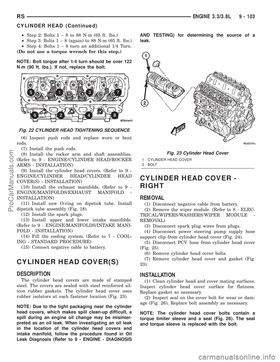
²Step 2: Bolts1±8to88N´m(65ft.lbs.)
²Step 3: Bolts1±8(again) to 88 N´m (65 ft. lbs.)
²Step 4: Bolts1±8turn an additional 1/4 Turn.
(Do not use a torque wrench for this step.)
NOTE: Bolt torque after 1/4 turn should be over 122
N´m (90 ft. lbs.). If not, replace the bolt.
(6) Inspect push rods and replace worn or bent
rods.
(7) Install the push rods.
(8) Install the rocker arm and shaft assemblies.
(Refer to 9 - ENGINE/CYLINDER HEAD/ROCKER
ARMS - INSTALLATION)
(9) Install the cylinder head covers. (Refer to 9 -
ENGINE/CYLINDER HEAD/CYLINDER HEAD
COVER(S) - INSTALLATION)
(10) Install the exhaust manifolds. (Refer to 9 -
ENGINE/MANIFOLDS/EXHAUST MANIFOLD -
INSTALLATION)
(11) Install new O-ring on dipstick tube. Install
dipstick tube assembly (Fig. 18).
(12) Install the spark plugs.
(13) Install upper and lower intake manifolds.
(Refer to 9 - ENGINE/MANIFOLDS/INTAKE MANI-
FOLD - INSTALLATION)
(14) Fill the cooling system. (Refer to 7 - COOL-
ING - STANDARD PROCEDURE)
(15) Connect negative cable to battery.
CYLINDER HEAD COVER(S)
DESCRIPTION
The cylinder head covers are made of stamped
steel. The covers are sealed with steel reinforced sil-
icon rubber gaskets. The cylinder head cover uses
rubber isolators at each fastener location (Fig. 23).
NOTE: Due to the tight packaging near the cylinder
head covers, which makes spill clean-up difficult, a
spill during an engine oil change may be misinter-
preted as an oil leak. When investigating an oil leak
in the location of the cylinder head covers and
intake manifold, follow the procedure found in Oil
Leak Diagnosis (Refer to 9 - ENGINE - DIAGNOSISAND TESTING) for determining the source of a
leak.
CYLINDER HEAD COVER -
RIGHT
REMOVAL
(1) Disconnect negative cable from battery.
(2) Remove the wiper module. (Refer to 8 - ELEC-
TRICAL/WIPERS/WASHERS/WIPER MODULE -
REMOVAL)
(3) Disconnect spark plug wires from plugs.
(4) Disconnect power steering pump supply hose
support clip from cylinder head cover (Fig. 24).
(5) Disconnect PCV hose from cylinder head cover
(Fig. 25).
(6) Remove cylinder head cover bolts.
(7) Remove cylinder head cover and gasket (Fig.
23).
INSTALLATION
(1) Clean cylinder head and cover mating surfaces.
Inspect cylinder head cover surface for flatness.
Replace gasket as necessary.
(2) Inspect seal on the cover bolt for wear or dam-
age (Fig. 26). Replace bolt assembly as necessary.
NOTE: The cylinder head cover bolts contain a
torque limiter sleeve and a seal (Fig. 26). The seal
and torque sleeve is replaced with the bolt.
Fig. 22 CYLINDER HEAD TIGHTENING SEQUENCE
Fig. 23 Cylinder Head Cover
1 - CYLINDER HEAD COVER
2 - BOLT
RSENGINE 3.3/3.8L9 - 103
CYLINDER HEAD (Continued)
ProCarManuals.com
Page 1305 of 2399
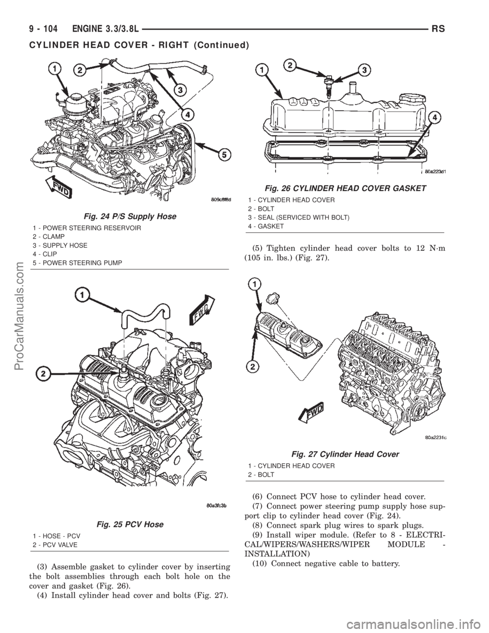
(3) Assemble gasket to cylinder cover by inserting
the bolt assemblies through each bolt hole on the
cover and gasket (Fig. 26).
(4) Install cylinder head cover and bolts (Fig. 27).(5) Tighten cylinder head cover bolts to 12 N´m
(105 in. lbs.) (Fig. 27).
(6) Connect PCV hose to cylinder head cover.
(7) Connect power steering pump supply hose sup-
port clip to cylinder head cover (Fig. 24).
(8) Connect spark plug wires to spark plugs.
(9) Install wiper module. (Refer to 8 - ELECTRI-
CAL/WIPERS/WASHERS/WIPER MODULE -
INSTALLATION)
(10) Connect negative cable to battery.
Fig. 24 P/S Supply Hose
1 - POWER STEERING RESERVOIR
2 - CLAMP
3 - SUPPLY HOSE
4 - CLIP
5 - POWER STEERING PUMP
Fig. 25 PCV Hose
1 - HOSE - PCV
2 - P C V VA LV E
Fig. 26 CYLINDER HEAD COVER GASKET
1 - CYLINDER HEAD COVER
2 - BOLT
3 - SEAL (SERVICED WITH BOLT)
4 - GASKET
Fig. 27 Cylinder Head Cover
1 - CYLINDER HEAD COVER
2 - BOLT
9 - 104 ENGINE 3.3/3.8LRS
CYLINDER HEAD COVER - RIGHT (Continued)
ProCarManuals.com
Page 1309 of 2399
REMOVAL
REMOVAL - CYLINDER HEAD OFF
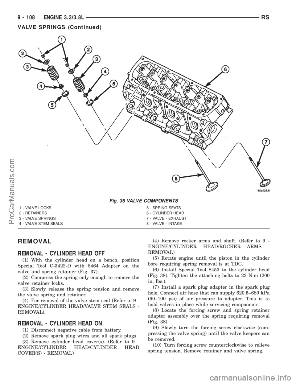
(1) With the cylinder head on a bench, position
Special Tool C-3422-D with 8464 Adapter on the
valve and spring retainer (Fig. 37).
(2) Compress the spring only enough to remove the
valve retainer locks.
(3) Slowly release the spring tension and remove
the valve spring and retainer.
(4) For removal of the valve stem seal (Refer to 9 -
ENGINE/CYLINDER HEAD/VALVE STEM SEALS -
REMOVAL).
REMOVAL - CYLINDER HEAD ON
(1) Disconnect negative cable from battery.
(2) Remove spark plug wires and all spark plugs.
(3) Remove cylinder head cover(s). (Refer to 9 -
ENGINE/CYLINDER HEAD/CYLINDER HEAD
COVER(S) - REMOVAL)(4) Remove rocker arms and shaft. (Refer to 9 -
ENGINE/CYLINDER HEAD/ROCKER ARMS -
REMOVAL)
(5) Rotate engine until the piston in the cylinder
bore requiring spring removal is at TDC.
(6) Install Special Tool 8453 to the cylinder head
(Fig. 38). Tighten the attaching bolts to 23 N´m (200
in. lbs.).
(7) Install a spark plug adapter in the spark plug
hole. Connect air hose that can supply 620.5±689 kPa
(90±100 psi) of air pressure to adapter. This is to
hold valves in place while servicing components.
(8) Locate the forcing screw and spring retainer
adapter assembly over the spring requiring removal
(Fig. 38).
(9) Slowly turn the forcing screw clockwise (com-
pressing the valve spring) until the valve keepers can
be removed.
(10) Turn forcing screw counterclockwise to relieve
spring tension. Remove retainer and valve spring.
Fig. 36 VALVE COMPONENTS
1 - VALVE LOCKS 5 - SPRING SEATS
2 - RETAINERS 6 - CYLINDER HEAD
3 - VALVE SPRINGS 7 - VALVE - EXHAUST
4 - VALVE STEM SEALS 8 - VALVE - INTAKE
9 - 108 ENGINE 3.3/3.8LRS
VALVE SPRINGS (Continued)
ProCarManuals.com
Page 1311 of 2399
(2) Follow the same procedure on the remaining 5
cylinders using the firing sequence 1-2-3-4-5-6.Make
sure piston in cylinder is at TDC on the valve
spring that is being covered.
(3) Remove spark plug adapter tool.
(4) Install rocker arms and shaft assembly. (Refer
to 9 - ENGINE/CYLINDER HEAD/ROCKER ARMS -
INSTALLATION)
(5) Install cylinder head covers. (Refer to 9 -
ENGINE/CYLINDER HEAD/CYLINDER HEAD
COVER(S) - INSTALLATION)
(6) Install spark plugs and connect wires.
(7) Connect negative cable to battery.
ROCKER ARMS
DESCRIPTION
DESCRIPTION - ROCKER ARMS
The rocker arms are installed on the rocker arm
shaft. The rocker arms and shaft assembly is
attached to the cylinder head with seven bolts and
retainers. The rocker arms are made of stamped
steel.
DESCRIPTION - PUSHRODS
The pushrods are made of steel and are a hollow
design. The pushrods are positioned between the
hydraulic lifter and the rocker arm.
OPERATION
OPERATION - ROCKER ARMS
The rocker arm pivots on the rocker shaft. Rocker
arms are used to translate up and down motions pro-
vided by the camshaft, hydraulic lifter, and pushrod
on one end, into a down and up motions on the valve
stem on the opposing end.
OPERATION - PUSHRODS
The pushrod is a solid link between the hydraulic
lifter and the rocker arm. Also, the pushrod supplies
engine oil from the hydraulic lifter to the rocker arm.
REMOVAL - ROCKER ARMS AND SHAFT
(1) Remove the cylinder head cover(s). (Refer to 9 -
ENGINE/CYLINDER HEAD/CYLINDER HEAD
COVER(S) - REMOVAL)
NOTE: Rocker arm shaft bolts are captured to the
shaft.
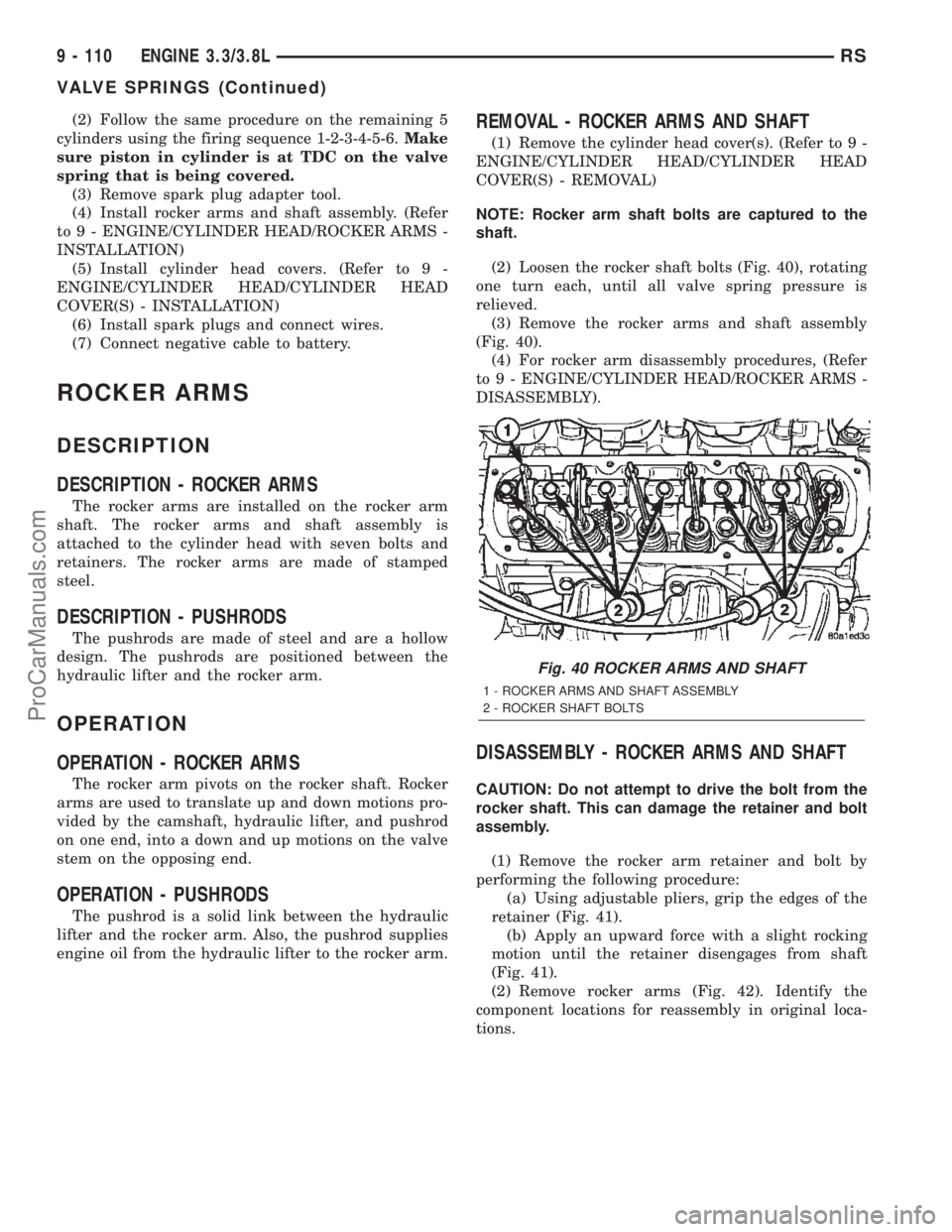
(2) Loosen the rocker shaft bolts (Fig. 40), rotating
one turn each, until all valve spring pressure is
relieved.
(3) Remove the rocker arms and shaft assembly
(Fig. 40).
(4) For rocker arm disassembly procedures, (Refer
to 9 - ENGINE/CYLINDER HEAD/ROCKER ARMS -
DISASSEMBLY).
DISASSEMBLY - ROCKER ARMS AND SHAFT
CAUTION: Do not attempt to drive the bolt from the
rocker shaft. This can damage the retainer and bolt
assembly.
(1) Remove the rocker arm retainer and bolt by
performing the following procedure:
(a) Using adjustable pliers, grip the edges of the
retainer (Fig. 41).
(b) Apply an upward force with a slight rocking
motion until the retainer disengages from shaft
(Fig. 41).
(2) Remove rocker arms (Fig. 42). Identify the
component locations for reassembly in original loca-
tions.
Fig. 40 ROCKER ARMS AND SHAFT
1 - ROCKER ARMS AND SHAFT ASSEMBLY
2 - ROCKER SHAFT BOLTS
9 - 110 ENGINE 3.3/3.8LRS
VALVE SPRINGS (Continued)
ProCarManuals.com
Page 1323 of 2399
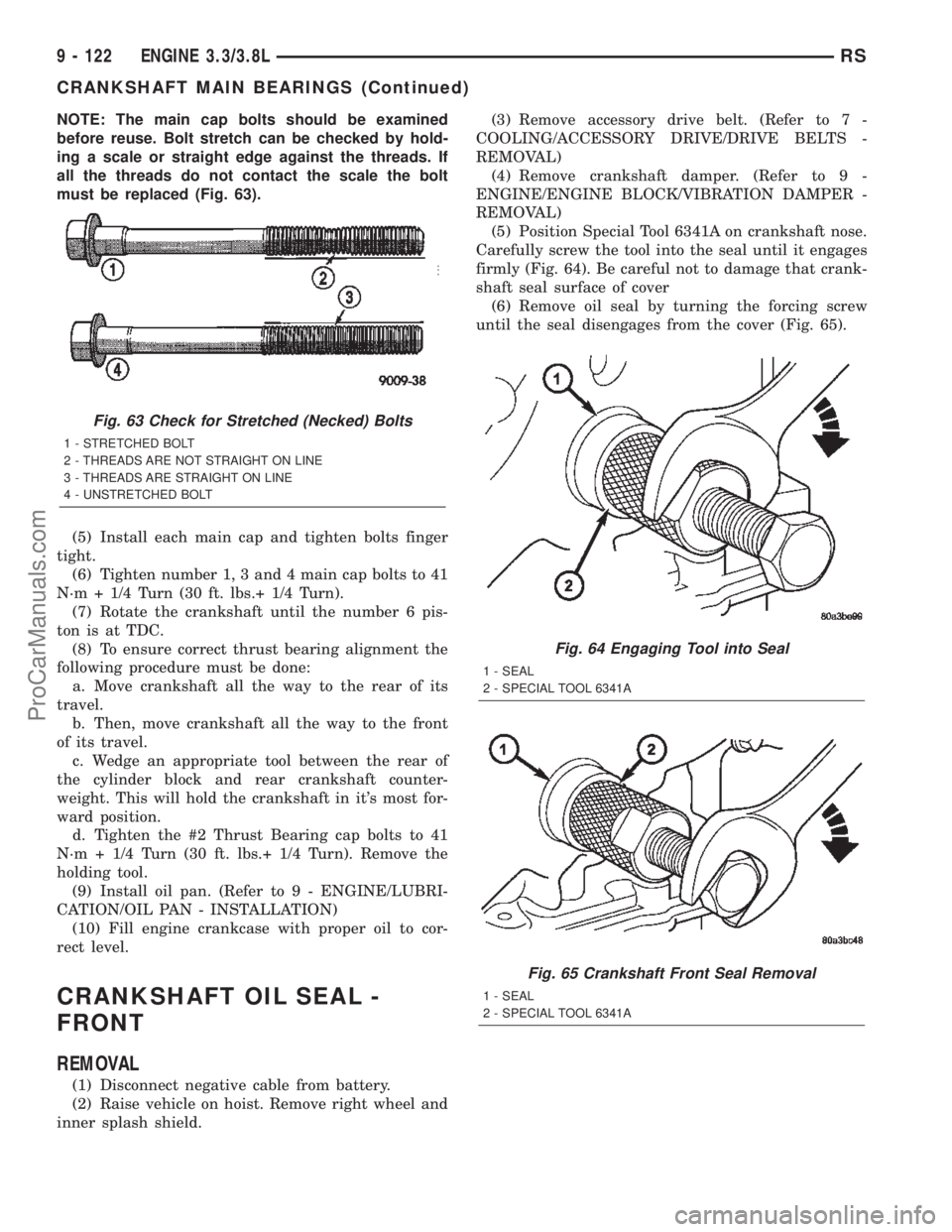
NOTE: The main cap bolts should be examined
before reuse. Bolt stretch can be checked by hold-
ing a scale or straight edge against the threads. If
all the threads do not contact the scale the bolt
must be replaced (Fig. 63).
(5) Install each main cap and tighten bolts finger
tight.
(6) Tighten number 1, 3 and 4 main cap bolts to 41
N´m + 1/4 Turn (30 ft. lbs.+ 1/4 Turn).
(7) Rotate the crankshaft until the number 6 pis-
ton is at TDC.
(8) To ensure correct thrust bearing alignment the
following procedure must be done:
a. Move crankshaft all the way to the rear of its
travel.
b. Then, move crankshaft all the way to the front
of its travel.
c. Wedge an appropriate tool between the rear of
the cylinder block and rear crankshaft counter-
weight. This will hold the crankshaft in it's most for-
ward position.
d. Tighten the #2 Thrust Bearing cap bolts to 41
N´m + 1/4 Turn (30 ft. lbs.+ 1/4 Turn). Remove the
holding tool.
(9) Install oil pan. (Refer to 9 - ENGINE/LUBRI-
CATION/OIL PAN - INSTALLATION)
(10) Fill engine crankcase with proper oil to cor-
rect level.
CRANKSHAFT OIL SEAL -
FRONT
REMOVAL
(1) Disconnect negative cable from battery.
(2) Raise vehicle on hoist. Remove right wheel and
inner splash shield.(3) Remove accessory drive belt. (Refer to 7 -
COOLING/ACCESSORY DRIVE/DRIVE BELTS -
REMOVAL)
(4) Remove crankshaft damper. (Refer to 9 -
ENGINE/ENGINE BLOCK/VIBRATION DAMPER -
REMOVAL)
(5) Position Special Tool 6341A on crankshaft nose.
Carefully screw the tool into the seal until it engages
firmly (Fig. 64). Be careful not to damage that crank-
shaft seal surface of cover
(6) Remove oil seal by turning the forcing screw
until the seal disengages from the cover (Fig. 65).
Fig. 63 Check for Stretched (Necked) Bolts
1 - STRETCHED BOLT
2 - THREADS ARE NOT STRAIGHT ON LINE
3 - THREADS ARE STRAIGHT ON LINE
4 - UNSTRETCHED BOLT
Fig. 64 Engaging Tool into Seal
1 - SEAL
2 - SPECIAL TOOL 6341A
Fig. 65 Crankshaft Front Seal Removal
1 - SEAL
2 - SPECIAL TOOL 6341A
9 - 122 ENGINE 3.3/3.8LRS
CRANKSHAFT MAIN BEARINGS (Continued)
ProCarManuals.com
Page 1324 of 2399
INSTALLATION
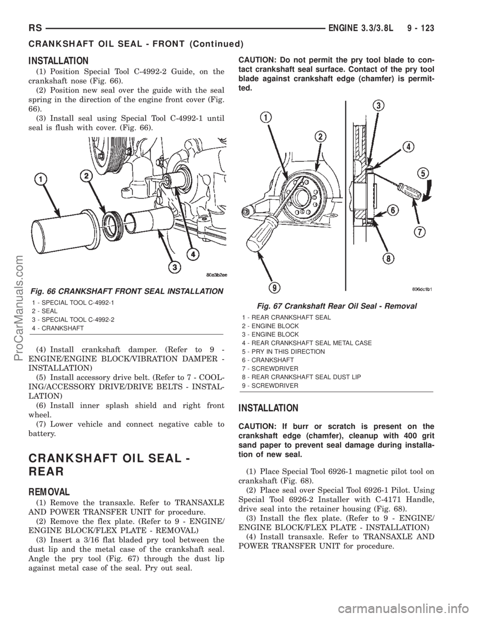
(1) Position Special Tool C-4992-2 Guide, on the
crankshaft nose (Fig. 66).
(2) Position new seal over the guide with the seal
spring in the direction of the engine front cover (Fig.
66).
(3) Install seal using Special Tool C-4992-1 until
seal is flush with cover. (Fig. 66).
(4) Install crankshaft damper. (Refer to 9 -
ENGINE/ENGINE BLOCK/VIBRATION DAMPER -
INSTALLATION)
(5) Install accessory drive belt. (Refer to 7 - COOL-
ING/ACCESSORY DRIVE/DRIVE BELTS - INSTAL-
LATION)
(6) Install inner splash shield and right front
wheel.
(7) Lower vehicle and connect negative cable to
battery.
CRANKSHAFT OIL SEAL -
REAR
REMOVAL
(1) Remove the transaxle. Refer to TRANSAXLE
AND POWER TRANSFER UNIT for procedure.
(2) Remove the flex plate. (Refer to 9 - ENGINE/
ENGINE BLOCK/FLEX PLATE - REMOVAL)
(3) Insert a 3/16 flat bladed pry tool between the
dust lip and the metal case of the crankshaft seal.
Angle the pry tool (Fig. 67) through the dust lip
against metal case of the seal. Pry out seal.CAUTION: Do not permit the pry tool blade to con-
tact crankshaft seal surface. Contact of the pry tool
blade against crankshaft edge (chamfer) is permit-
ted.
INSTALLATION
CAUTION: If burr or scratch is present on the
crankshaft edge (chamfer), cleanup with 400 grit
sand paper to prevent seal damage during installa-
tion of new seal.
(1) Place Special Tool 6926-1 magnetic pilot tool on
crankshaft (Fig. 68).
(2) Place seal over Special Tool 6926-1 Pilot. Using
Special Tool 6926-2 Installer with C-4171 Handle,
drive seal into the retainer housing (Fig. 68).
(3) Install the flex plate. (Refer to 9 - ENGINE/
ENGINE BLOCK/FLEX PLATE - INSTALLATION)
(4) Install transaxle. Refer to TRANSAXLE AND
POWER TRANSFER UNIT for procedure.
Fig. 66 CRANKSHAFT FRONT SEAL INSTALLATION
1 - SPECIAL TOOL C-4992-1
2 - SEAL
3 - SPECIAL TOOL C-4992-2
4 - CRANKSHAFTFig. 67 Crankshaft Rear Oil Seal - Removal
1 - REAR CRANKSHAFT SEAL
2 - ENGINE BLOCK
3 - ENGINE BLOCK
4 - REAR CRANKSHAFT SEAL METAL CASE
5 - PRY IN THIS DIRECTION
6 - CRANKSHAFT
7 - SCREWDRIVER
8 - REAR CRANKSHAFT SEAL DUST LIP
9 - SCREWDRIVER
RSENGINE 3.3/3.8L9 - 123
CRANKSHAFT OIL SEAL - FRONT (Continued)
ProCarManuals.com
Page 1328 of 2399
STANDARD PROCEDURE
STANDARD PROCEDURE - FITTING
CONNECTING RODS
The bearing caps are not interchangeable or
reversible, and should be marked at removal to
ensure correct reassembly. The bearing shells must
be installed with the tangs inserted into the
machined grooves in the rods and caps. Install cap
with the tangs on the same side as the rod. For con-
necting rod bearing fitting (Refer to 9 - ENGINE/EN-
GINE BLOCK/CONNECTING ROD BEARINGS -
STANDARD PROCEDURE). Fit all connecting rods
on one bank until complete.
NOTE: The connecting rod cap bolts should be
examined before reuse. Bolt stretch can be checked
by holding a scale or straight edge against the
threads. If all the threads do not contact the scale
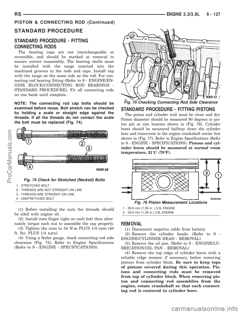
the bolt must be replaced (Fig. 74).
(1) Before installing the nuts the threads should
be oiled with engine oil.
(2) Install nuts finger tight on each bolt then alter-
nately torque each nut to assemble the cap properly.
(3) Tighten the nuts to 54 N´m PLUS 1/4 turn (40
ft. lbs. PLUS 1/4 turn).
(4) Using a feeler gauge, check connecting rod side
clearance (Fig. 75). Refer to Engine Specifications
(Refer to 9 - ENGINE - SPECIFICATIONS).
STANDARD PROCEDURE - FITTING PISTONS
The piston and cylinder wall must be clean and dry.
Piston diameter should be measured 90 degrees to pis-
ton pin at size location shown in (Fig. 76). Cylinder
bores should be measured halfway down the cylinder
bore and transverse to the engine crankshaft center line
shown in (Fig. 77). Refer to Engine Specifications (Refer
to 9 - ENGINE - SPECIFICATIONS).Pistons and cyl-
inder bores should be measured at normal room
temperature, 21ÉC (70ÉF).
REMOVAL
(1) Disconnect negative cable from battery.
(2) Remove the cylinder heads. (Refer to 9 -
ENGINE/CYLINDER HEAD - REMOVAL)
(3) Remove the oil pan. (Refer to 9 - ENGINE/LU-
BRICATION/OIL PAN - REMOVAL)
(4) Remove the top ridge of cylinder bores with a
reliable ridge reamer, if necessary, before removing
pistons from cylinder block.Be sure to keep tops
of pistons covered during this operation. Pis-
tons and connecting rods must be removed
from top of cylinder block. When removing pis-
ton and connecting rod assemblies from the
engine, rotate crankshaft so that each connect-
ing rod is centered in cylinder bore.
Fig. 74 Check for Stretched (Necked) Bolts
1 - STRETCHED BOLT
2 - THREADS ARE NOT STRAIGHT ON LINE
3 - THREADS ARE STRAIGHT ON LINE
4 - UNSTRETCHED BOLT
Fig. 75 Checking Connecting Rod Side Clearance
Fig. 76 Piston Measurement Locations
1 - 39.8 mm (1.56 in. ) 3.3L ENGINE
2 - 33.0 mm (1.29 in.) 3.8L ENGINE
RSENGINE 3.3/3.8L9 - 127
PISTON & CONNECTING ROD (Continued)
ProCarManuals.com