2002 CHRYSLER CARAVAN battery
[x] Cancel search: batteryPage 1100 of 2399
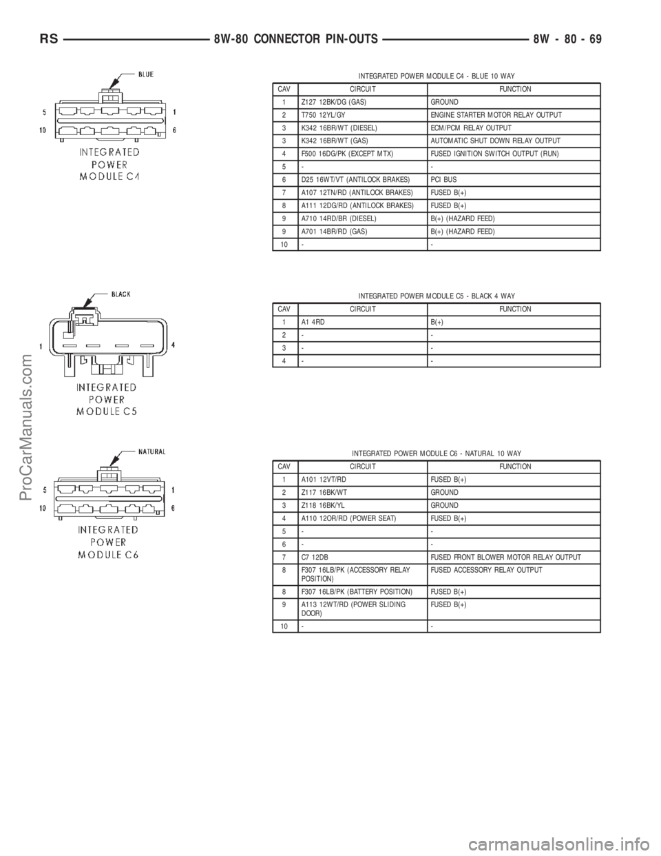
INTEGRATED POWER MODULE C4 - BLUE 10 WAY
CAV CIRCUIT FUNCTION
1 Z127 12BK/DG (GAS) GROUND
2 T750 12YL/GY ENGINE STARTER MOTOR RELAY OUTPUT
3 K342 16BR/WT (DIESEL) ECM/PCM RELAY OUTPUT
3 K342 16BR/WT (GAS) AUTOMATIC SHUT DOWN RELAY OUTPUT
4 F500 16DG/PK (EXCEPT MTX) FUSED IGNITION SWITCH OUTPUT (RUN)
5- -
6 D25 16WT/VT (ANTILOCK BRAKES) PCI BUS
7 A107 12TN/RD (ANTILOCK BRAKES) FUSED B(+)
8 A111 12DG/RD (ANTILOCK BRAKES) FUSED B(+)
9 A710 14RD/BR (DIESEL) B(+) (HAZARD FEED)
9 A701 14BR/RD (GAS) B(+) (HAZARD FEED)
10 - -
INTEGRATED POWER MODULE C5 - BLACK 4 WAY
CAV CIRCUIT FUNCTION
1 A1 4RD B(+)
2- -
3- -
4- -
INTEGRATED POWER MODULE C6 - NATURAL 10 WAY
CAV CIRCUIT FUNCTION
1 A101 12VT/RD FUSED B(+)
2 Z117 16BK/WT GROUND
3 Z118 16BK/YL GROUND
4 A110 12OR/RD (POWER SEAT) FUSED B(+)
5- -
6- -
7 C7 12DB FUSED FRONT BLOWER MOTOR RELAY OUTPUT
8 F307 16LB/PK (ACCESSORY RELAY
POSITION)FUSED ACCESSORY RELAY OUTPUT
8 F307 16LB/PK (BATTERY POSITION) FUSED B(+)
9 A113 12WT/RD (POWER SLIDING
DOOR)FUSED B(+)
10 - -
RS8W-80 CONNECTOR PIN-OUTS8W-80-69
ProCarManuals.com
Page 1132 of 2399
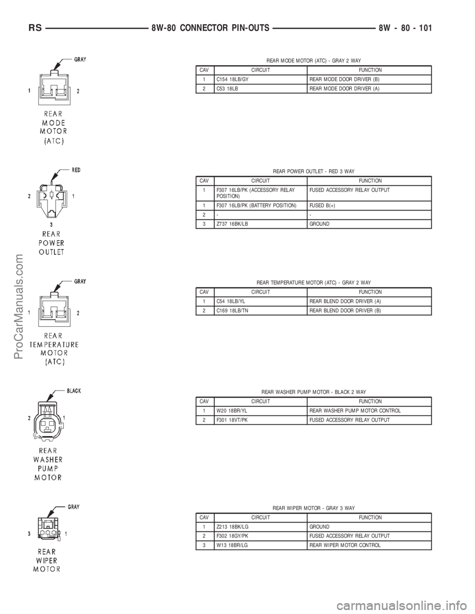
REAR MODE MOTOR (ATC) - GRAY 2 WAY
CAV CIRCUIT FUNCTION
1 C154 18LB/GY REAR MODE DOOR DRIVER (B)
2 C53 18LB REAR MODE DOOR DRIVER (A)
REAR POWER OUTLET - RED 3 WAY
CAV CIRCUIT FUNCTION
1 F307 16LB/PK (ACCESSORY RELAY
POSITION)FUSED ACCESSORY RELAY OUTPUT
1 F307 16LB/PK (BATTERY POSITION) FUSED B(+)
2- -
3 Z737 16BK/LB GROUND
REAR TEMPERATURE MOTOR (ATC) - GRAY 2 WAY
CAV CIRCUIT FUNCTION
1 C54 18LB/YL REAR BLEND DOOR DRIVER (A)
2 C169 18LB/TN REAR BLEND DOOR DRIVER (B)
REAR WASHER PUMP MOTOR - BLACK 2 WAY
CAV CIRCUIT FUNCTION
1 W20 18BR/YL REAR WASHER PUMP MOTOR CONTROL
2 F301 18VT/PK FUSED ACCESSORY RELAY OUTPUT
REAR WIPER MOTOR - GRAY 3 WAY
CAV CIRCUIT FUNCTION
1 Z213 18BK/LG GROUND
2 F302 18GY/PK FUSED ACCESSORY RELAY OUTPUT
3 W13 18BR/LG REAR WIPER MOTOR CONTROL
RS8W-80 CONNECTOR PIN-OUTS8W - 80 - 101
ProCarManuals.com
Page 1148 of 2399
8W-91 CONNECTOR/GROUND/SPLICE LOCATION
TABLE OF CONTENTS
page
CONNECTOR/GROUND/SPLICE LOCATION
DESCRIPTION..........................1
CONNECTOR/GROUND/SPLICE
LOCATION
DESCRIPTION
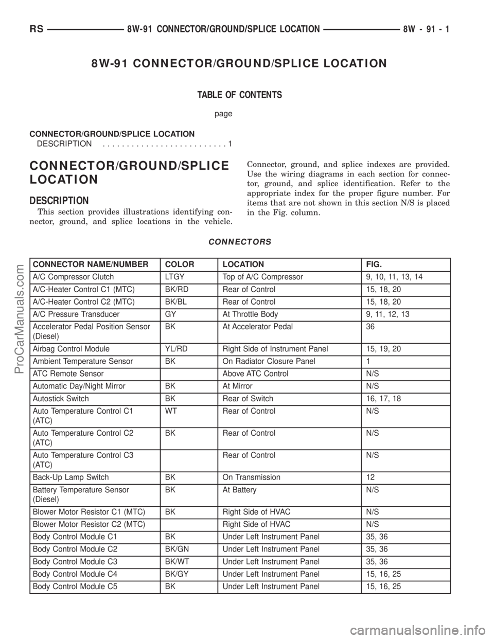
This section provides illustrations identifying con-
nector, ground, and splice locations in the vehicle.Connector, ground, and splice indexes are provided.
Use the wiring diagrams in each section for connec-
tor, ground, and splice identification. Refer to the
appropriate index for the proper figure number. For
items that are not shown in this section N/S is placed
in the Fig. column.
CONNECTORS
CONNECTOR NAME/NUMBER COLOR LOCATION FIG.
A/C Compressor Clutch LTGY Top of A/C Compressor 9, 10, 11, 13, 14
A/C-Heater Control C1 (MTC) BK/RD Rear of Control 15, 18, 20
A/C-Heater Control C2 (MTC) BK/BL Rear of Control 15, 18, 20
A/C Pressure Transducer GY At Throttle Body 9, 11, 12, 13
Accelerator Pedal Position Sensor
(Diesel)BK At Accelerator Pedal 36
Airbag Control Module YL/RD Right Side of Instrument Panel 15, 19, 20
Ambient Temperature Sensor BK On Radiator Closure Panel 1
ATC Remote Sensor Above ATC Control N/S
Automatic Day/Night Mirror BK At Mirror N/S
Autostick Switch BK Rear of Switch 16, 17, 18
Auto Temperature Control C1
(ATC)WT Rear of Control N/S
Auto Temperature Control C2
(ATC)BK Rear of Control N/S
Auto Temperature Control C3
(ATC)Rear of Control N/S
Back-Up Lamp Switch BK On Transmission 12
Battery Temperature Sensor
(Diesel)BK At Battery N/S
Blower Motor Resistor C1 (MTC) BK Right Side of HVAC N/S
Blower Motor Resistor C2 (MTC) Right Side of HVAC N/S
Body Control Module C1 BK Under Left Instrument Panel 35, 36
Body Control Module C2 BK/GN Under Left Instrument Panel 35, 36
Body Control Module C3 BK/WT Under Left Instrument Panel 35, 36
Body Control Module C4 BK/GY Under Left Instrument Panel 15, 16, 25
Body Control Module C5 BK Under Left Instrument Panel 15, 16, 25
RS8W-91 CONNECTOR/GROUND/SPLICE LOCATION8W-91-1
ProCarManuals.com
Page 1152 of 2399
CONNECTOR NAME/NUMBER COLOR LOCATION FIG.
Fuel Injector No.3 BK At Fuel Injector N/S
Fuel Injector No.3 (Diesel) BK At Fuel Injector 11
Fuel Injector No.4 BK At Fuel Injector N/S
Fuel Injector No.4 (Diesel) BK At Fuel Injector 11
Fuel Injector No.5 BK At Fuel Injector N/S
Fuel Injector No.6 BK At Fuel Injector N/S
Fuel Pump Module LTGY Side of Fuel Tank N/S
Fuel Pressure Sensor (Diesel) BK Top Left of Engine 11
Generator BK Rear of Generator 10, 11, 13, 14
Glove Box Lamp BL Rear of Glove Box 18, 24
Glow Plug Relay (Diesel) BK Near Battery N/S
Halo Lamp WT Steering Column 15, 16, 17, 18, 26
Headlamp Switch BK Rear of Switch 15, 16, 25
Headlamp Washer Pump Motor At Motor N/S
High Note Horn BK Left Frame Rail 5
High Pressure Fuel Pump (Diesel) Rear of Pump 11
Hood Ajar Switch BK Left Fender 6
Idle Air Control Motor (2.4L) BK On Throttle Body 9
Idle Air Control Motor (3.3/3.8L) BK On Throttle Body 13
Ignition Coil Pack 2.4L BK Top of Valve Cover 9, 10
Ignition Coil Pack 3.3L, 3.8L DKGY Top of Engine 14
Ignition Switch BK Rear of Switch at Steering Column 15, 16, 17, 18, 26
Inlet Air Temperature Sensor BK Top Left of Engine N/S
Instrument Cluster BK Rear of Cluster 15, 16, 23
Instrument Panel Switch Bank BK Right Center of Instrument Panel 15, 18, 20
Instrument Panel Power Outlet NAT Center of Instrument Panel N/S
Integrated Power Module C1 LTGN Left Fender Shield 7
Integrated Power Module C2 GN/BL Left Fender Shield 7
Integrated Power Module C3
(Diesel)YL/RD Left Fender Shield 7
Integrated Power Module C3 (Gas) NAT/RD Left Fender Shield 7
Integrated Power Module C4 BL Left Fender Shield 7
Integrated Power Module C5 BK Left Fender Shield 7
Integrated Power Module C6 NAT Left Fender Shield 7
Integrated Power Module C7 BK/RD Left Fender Shield 7
Integrated Power Module C8 OR Left Fender Shield 7
Integrated Power Module C9 BK Left Fender Shield 7
Knock Sensor GY Front of Cylinder Block N/S
Leak Detection Pump LTGY At Pump 9, 10 14
Left B Pillar Switch GY Left B Pillar 34
Left Cinch/Release Motor GY Left Sliding Door N/S
Left Combination Relay BK Left Rear Quarter Panel N/S
RS8W-91 CONNECTOR/GROUND/SPLICE LOCATION8W-91-5
CONNECTOR/GROUND/SPLICE LOCATION (Continued)
ProCarManuals.com
Page 1158 of 2399
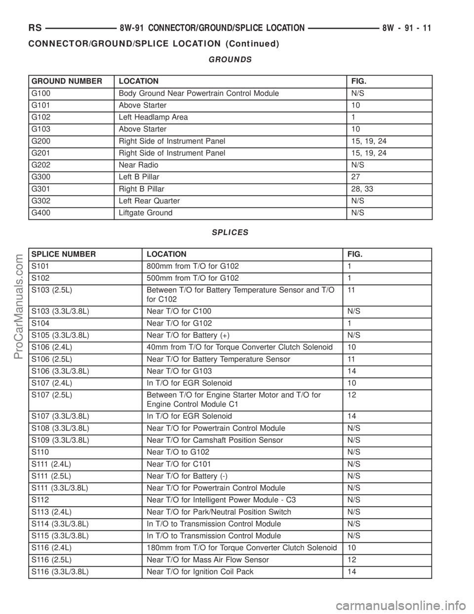
GROUNDS
GROUND NUMBER LOCATION FIG.
G100 Body Ground Near Powertrain Control Module N/S
G101 Above Starter 10
G102 Left Headlamp Area 1
G103 Above Starter 10
G200 Right Side of Instrument Panel 15, 19, 24
G201 Right Side of Instrument Panel 15, 19, 24
G202 Near Radio N/S
G300 Left B Pillar 27
G301 Right B Pillar 28, 33
G302 Left Rear Quarter N/S
G400 Liftgate Ground N/S
SPLICES
SPLICE NUMBER LOCATION FIG.
S101 800mm from T/O for G102 1
S102 500mm from T/O for G102 1
S103 (2.5L) Between T/O for Battery Temperature Sensor and T/O
for C10211
S103 (3.3L/3.8L) Near T/O for C100 N/S
S104 Near T/O for G102 1
S105 (3.3L/3.8L) Near T/O for Battery (+) N/S
S106 (2.4L) 40mm from T/O for Torque Converter Clutch Solenoid 10
S106 (2.5L) Near T/O for Battery Temperature Sensor 11
S106 (3.3L/3.8L) Near T/O for G103 14
S107 (2.4L) In T/O for EGR Solenoid 10
S107 (2.5L) Between T/O for Engine Starter Motor and T/O for
Engine Control Module C112
S107 (3.3L/3.8L) In T/O for EGR Solenoid 14
S108 (3.3L/3.8L) Near T/O for Powertrain Control Module N/S
S109 (3.3L/3.8L) Near T/O for Camshaft Position Sensor N/S
S110 Near T/O to G102 N/S
S111 (2.4L) Near T/O for C101 N/S
S111 (2.5L) Near T/O for Battery (-) N/S
S111 (3.3L/3.8L) Near T/O for Powertrain Control Module N/S
S112 Near T/O for Intelligent Power Module - C3 N/S
S113 (2.4L) Near T/O for Park/Neutral Position Switch N/S
S114 (3.3L/3.8L) In T/O to Transmission Control Module N/S
S115 (3.3L/3.8L) In T/O to Transmission Control Module N/S
S116 (2.4L) 180mm from T/O for Torque Converter Clutch Solenoid 10
S116 (2.5L) Near T/O for Mass Air Flow Sensor 12
S116 (3.3L/3.8L) Near T/O for Ignition Coil Pack 14
RS8W-91 CONNECTOR/GROUND/SPLICE LOCATION8W-91-11
CONNECTOR/GROUND/SPLICE LOCATION (Continued)
ProCarManuals.com
Page 1159 of 2399
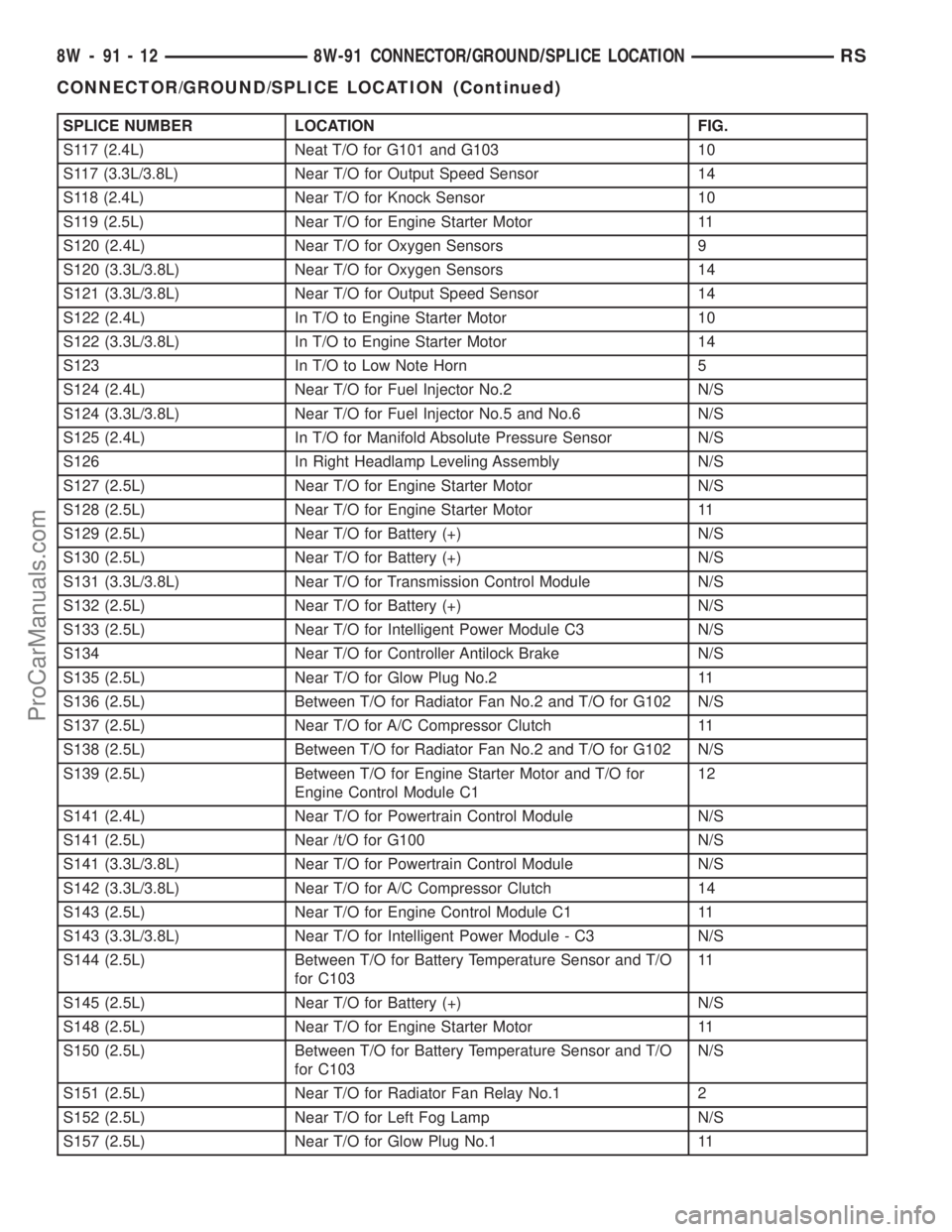
SPLICE NUMBER LOCATION FIG.
S117 (2.4L) Neat T/O for G101 and G103 10
S117 (3.3L/3.8L) Near T/O for Output Speed Sensor 14
S118 (2.4L) Near T/O for Knock Sensor 10
S119 (2.5L) Near T/O for Engine Starter Motor 11
S120 (2.4L) Near T/O for Oxygen Sensors 9
S120 (3.3L/3.8L) Near T/O for Oxygen Sensors 14
S121 (3.3L/3.8L) Near T/O for Output Speed Sensor 14
S122 (2.4L) In T/O to Engine Starter Motor 10
S122 (3.3L/3.8L) In T/O to Engine Starter Motor 14
S123 In T/O to Low Note Horn 5
S124 (2.4L) Near T/O for Fuel Injector No.2 N/S
S124 (3.3L/3.8L) Near T/O for Fuel Injector No.5 and No.6 N/S
S125 (2.4L) In T/O for Manifold Absolute Pressure Sensor N/S
S126 In Right Headlamp Leveling Assembly N/S
S127 (2.5L) Near T/O for Engine Starter Motor N/S
S128 (2.5L) Near T/O for Engine Starter Motor 11
S129 (2.5L) Near T/O for Battery (+) N/S
S130 (2.5L) Near T/O for Battery (+) N/S
S131 (3.3L/3.8L) Near T/O for Transmission Control Module N/S
S132 (2.5L) Near T/O for Battery (+) N/S
S133 (2.5L) Near T/O for Intelligent Power Module C3 N/S
S134 Near T/O for Controller Antilock Brake N/S
S135 (2.5L) Near T/O for Glow Plug No.2 11
S136 (2.5L) Between T/O for Radiator Fan No.2 and T/O for G102 N/S
S137 (2.5L) Near T/O for A/C Compressor Clutch 11
S138 (2.5L) Between T/O for Radiator Fan No.2 and T/O for G102 N/S
S139 (2.5L) Between T/O for Engine Starter Motor and T/O for
Engine Control Module C112
S141 (2.4L) Near T/O for Powertrain Control Module N/S
S141 (2.5L) Near /t/O for G100 N/S
S141 (3.3L/3.8L) Near T/O for Powertrain Control Module N/S
S142 (3.3L/3.8L) Near T/O for A/C Compressor Clutch 14
S143 (2.5L) Near T/O for Engine Control Module C1 11
S143 (3.3L/3.8L) Near T/O for Intelligent Power Module - C3 N/S
S144 (2.5L) Between T/O for Battery Temperature Sensor and T/O
for C10311
S145 (2.5L) Near T/O for Battery (+) N/S
S148 (2.5L) Near T/O for Engine Starter Motor 11
S150 (2.5L) Between T/O for Battery Temperature Sensor and T/O
for C103N/S
S151 (2.5L) Near T/O for Radiator Fan Relay No.1 2
S152 (2.5L) Near T/O for Left Fog Lamp N/S
S157 (2.5L) Near T/O for Glow Plug No.1 11
8W - 91 - 12 8W-91 CONNECTOR/GROUND/SPLICE LOCATIONRS
CONNECTOR/GROUND/SPLICE LOCATION (Continued)
ProCarManuals.com
Page 1197 of 2399
SPECIAL TOOLS
POWER DISTRIBUTION SYSTEMS
ACCESSORY RELAY
DESCRIPTION
The accessory relay is an electromechanical device
that switches fused battery current to the accessory
powered vehicle circuits when the ignition switch is
turned to the Accessory or On positions. The delay
feature will maintain power to the accessories for 45
seconds after the ignition is shut off or until a door is
opened. This allows sufficient time to close windows
and park the windshield wipers. The accessory relay
is located in the Integrated Power Module (IPM) in
the engine compartment.
The accessory relay is a International Standards
Organization (ISO) relay. Relays conforming to the
ISO specifications have common physical dimensions,
current capacities, terminal patterns, and terminal
functions.
The accessory relay cannot be repaired or adjusted
and, if faulty or damaged, it must be replaced.
OPERATION
The ISO relay consists of an electromagnetic coil, a
resistor or diode, and three (two fixed and one movable)
electrical contacts. The movable (common feed) relay
contact is held against one of the fixed contacts (normal-
ly closed) by spring pressure. When the electromagnetic
coil is energized, it draws the movable contact away
from the normally closed fixed contact, and holds it
against the other (normally open) fixed contact.
When the electromagnetic coil is de-energized,
spring pressure returns the movable contact to the
normally closed position. The resistor or diode is con-
nected in parallel with the electromagnetic coil in the
relay, and helps to dissipate voltage spikes that are
produced when the coil is de-energized.
DIAGNOSIS AND TESTING
DIAGNOSIS & TESTING - ACCESSORY RELAY
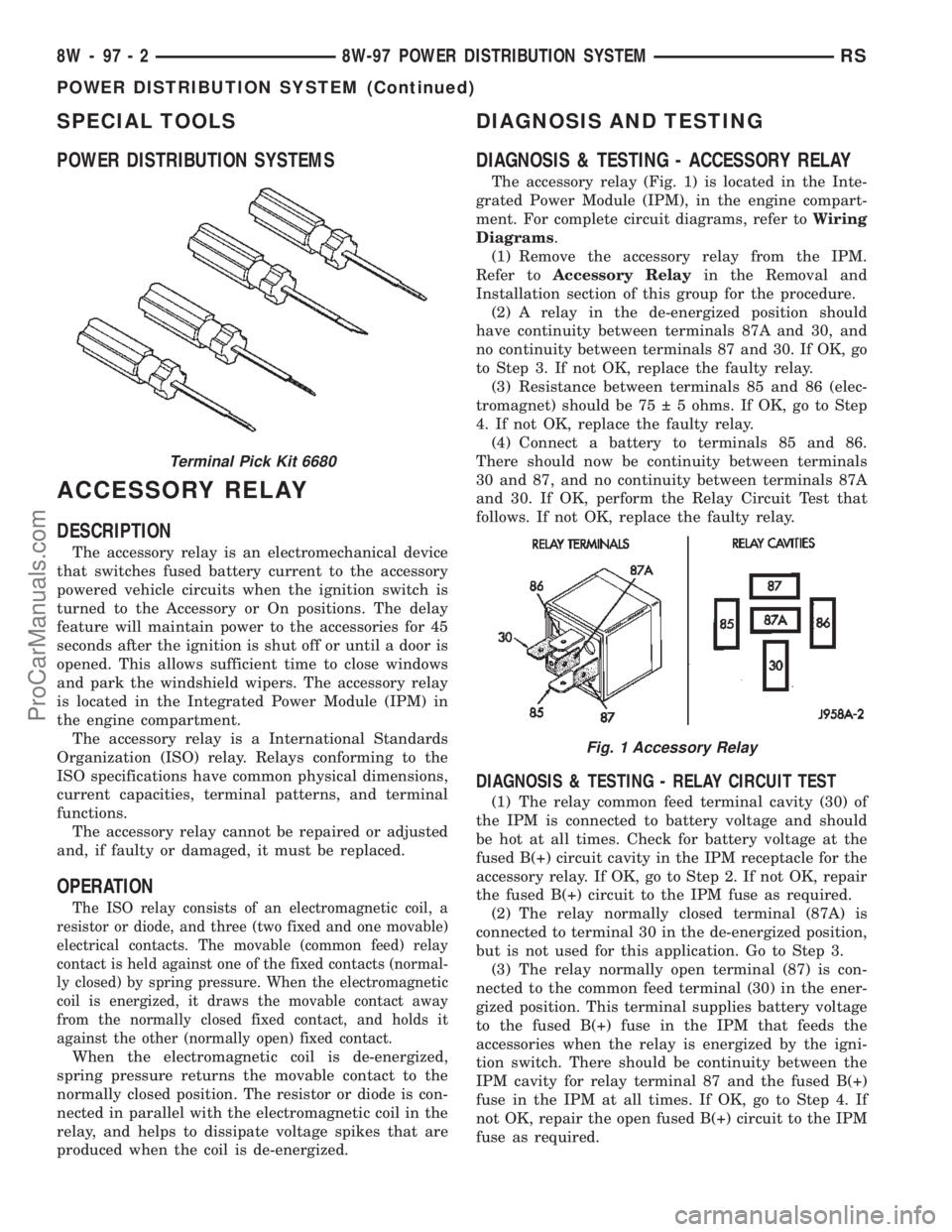
The accessory relay (Fig. 1) is located in the Inte-
grated Power Module (IPM), in the engine compart-
ment. For complete circuit diagrams, refer toWiring
Diagrams.
(1) Remove the accessory relay from the IPM.
Refer toAccessory Relayin the Removal and
Installation section of this group for the procedure.
(2) A relay in the de-energized position should
have continuity between terminals 87A and 30, and
no continuity between terminals 87 and 30. If OK, go
to Step 3. If not OK, replace the faulty relay.
(3) Resistance between terminals 85 and 86 (elec-
tromagnet) should be 75 5 ohms. If OK, go to Step
4. If not OK, replace the faulty relay.
(4) Connect a battery to terminals 85 and 86.
There should now be continuity between terminals
30 and 87, and no continuity between terminals 87A
and 30. If OK, perform the Relay Circuit Test that
follows. If not OK, replace the faulty relay.
DIAGNOSIS & TESTING - RELAY CIRCUIT TEST
(1) The relay common feed terminal cavity (30) of
the IPM is connected to battery voltage and should
be hot at all times. Check for battery voltage at the
fused B(+) circuit cavity in the IPM receptacle for the
accessory relay. If OK, go to Step 2. If not OK, repair
the fused B(+) circuit to the IPM fuse as required.
(2) The relay normally closed terminal (87A) is
connected to terminal 30 in the de-energized position,
but is not used for this application. Go to Step 3.
(3) The relay normally open terminal (87) is con-
nected to the common feed terminal (30) in the ener-
gized position. This terminal supplies battery voltage
to the fused B(+) fuse in the IPM that feeds the
accessories when the relay is energized by the igni-
tion switch. There should be continuity between the
IPM cavity for relay terminal 87 and the fused B(+)
fuse in the IPM at all times. If OK, go to Step 4. If
not OK, repair the open fused B(+) circuit to the IPM
fuse as required.
Terminal Pick Kit 6680
Fig. 1 Accessory Relay
8W - 97 - 2 8W-97 POWER DISTRIBUTION SYSTEMRS
POWER DISTRIBUTION SYSTEM (Continued)
ProCarManuals.com
Page 1198 of 2399
(4) The coil ground terminal (85) is connected to
the electromagnet in the relay. It receives battery
feed to energize the accessory relay when the ignition
switch is in the Accessory or On positions. Turn the
ignition switch to the On position. Check for battery
voltage at the fused ignition switch output (acc/run)
circuit cavity for relay terminal 85 in the IPM recep-
tacle for the accessory relay. If OK, go to Step 5. If
not OK, repair the open fused ignition switch output
(acc/run) circuit to the ignition switch as required.
(5) The coil battery terminal (86) is connected to
the electromagnet in the relay. The IPM cavity for
this terminal should have continuity to ground at all
times. If not OK, repair the open ground circuit to
ground as required.
REMOVAL
(1) Disconnect and isolate the battery negative
cable.
(2) Remove the Integrated Power Module (IPM)
cover from the IPM.
(3) Remove the accessory relay from the IPM.
Refer to the IPM cover for relay location.
INSTALLATION
(1) Position the accessory relay in the proper
receptacle in the Integrated Power Module (IPM).
(2) Push in firmly on the accessory relay until the
terminals are fully seated in the terminal cavities in
the IPM receptacle.
(3) Install the IPM cover.
(4) Reconnect the battery negative cable.
INTEGRATED POWER MODULE
DESCRIPTION
The Integrated Power Module (IPM) is a combina-
tion of the Power Distribution Center (PDC) and the
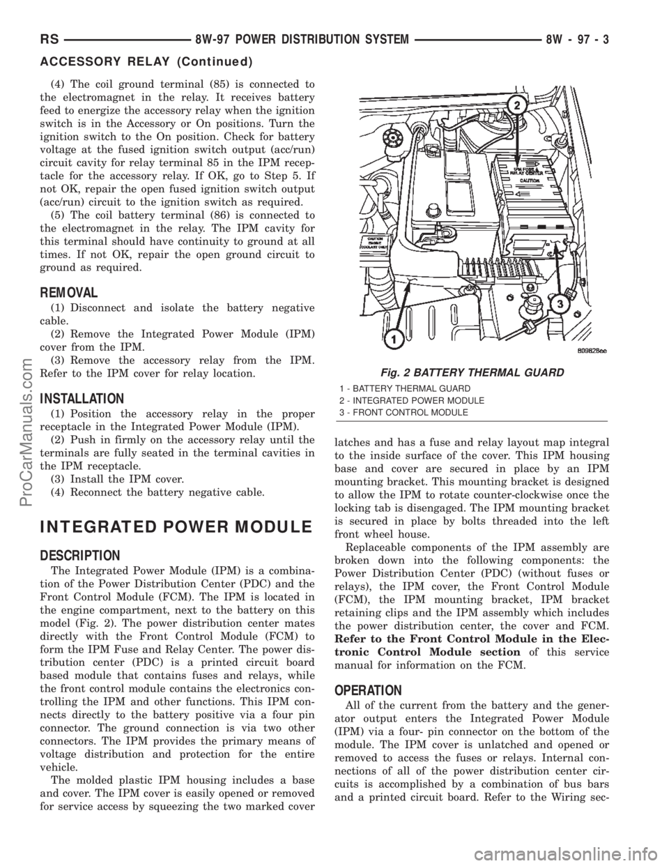
Front Control Module (FCM). The IPM is located in
the engine compartment, next to the battery on this
model (Fig. 2). The power distribution center mates
directly with the Front Control Module (FCM) to
form the IPM Fuse and Relay Center. The power dis-
tribution center (PDC) is a printed circuit board
based module that contains fuses and relays, while
the front control module contains the electronics con-
trolling the IPM and other functions. This IPM con-
nects directly to the battery positive via a four pin
connector. The ground connection is via two other
connectors. The IPM provides the primary means of
voltage distribution and protection for the entire
vehicle.
The molded plastic IPM housing includes a base
and cover. The IPM cover is easily opened or removed
for service access by squeezing the two marked coverlatches and has a fuse and relay layout map integral
to the inside surface of the cover. This IPM housing
base and cover are secured in place by an IPM
mounting bracket. This mounting bracket is designed
to allow the IPM to rotate counter-clockwise once the
locking tab is disengaged. The IPM mounting bracket
is secured in place by bolts threaded into the left
front wheel house.
Replaceable components of the IPM assembly are
broken down into the following components: the
Power Distribution Center (PDC) (without fuses or
relays), the IPM cover, the Front Control Module
(FCM), the IPM mounting bracket, IPM bracket
retaining clips and the IPM assembly which includes
the power distribution center, the cover and FCM.
Refer to the Front Control Module in the Elec-
tronic Control Module sectionof this service
manual for information on the FCM.
OPERATION
All of the current from the battery and the gener-
ator output enters the Integrated Power Module
(IPM) via a four- pin connector on the bottom of the
module. The IPM cover is unlatched and opened or
removed to access the fuses or relays. Internal con-
nections of all of the power distribution center cir-
cuits is accomplished by a combination of bus bars
and a printed circuit board. Refer to the Wiring sec-
Fig. 2 BATTERY THERMAL GUARD
1 - BATTERY THERMAL GUARD
2 - INTEGRATED POWER MODULE
3 - FRONT CONTROL MODULE
RS8W-97 POWER DISTRIBUTION SYSTEM8W-97-3
ACCESSORY RELAY (Continued)
ProCarManuals.com