2002 CHRYSLER CARAVAN battery
[x] Cancel search: batteryPage 1331 of 2399
(11) Install the cylinder heads. (Refer to 9 -
ENGINE/CYLINDER HEAD - INSTALLATION)
(12) Install the oil pan. (Refer to 9 - ENGINE/LU-
BRICATION/OIL PAN - INSTALLATION)
(13) Fill engine crankcase with proper oil to cor-
rect level.
(14) Connect negative cable to battery.PISTON RINGS
STANDARD PROCEDURE - PISTON RING
FITTING
(1) Wipe cylinder bore clean. Insert the ring and
push down with piston to ensure squareness in bore
to approximately 12 mm (0.50 in.) from top of cylin-
der bore. Check ring gap with a feeler gauge (Fig.
83). For clearance specification (Refer to 9 - ENGINE
- SPECIFICATIONS).
(2) Check piston ring to groove side clearance (Fig.
84). For clearance specification (Refer to 9 - ENGINE
- SPECIFICATIONS)
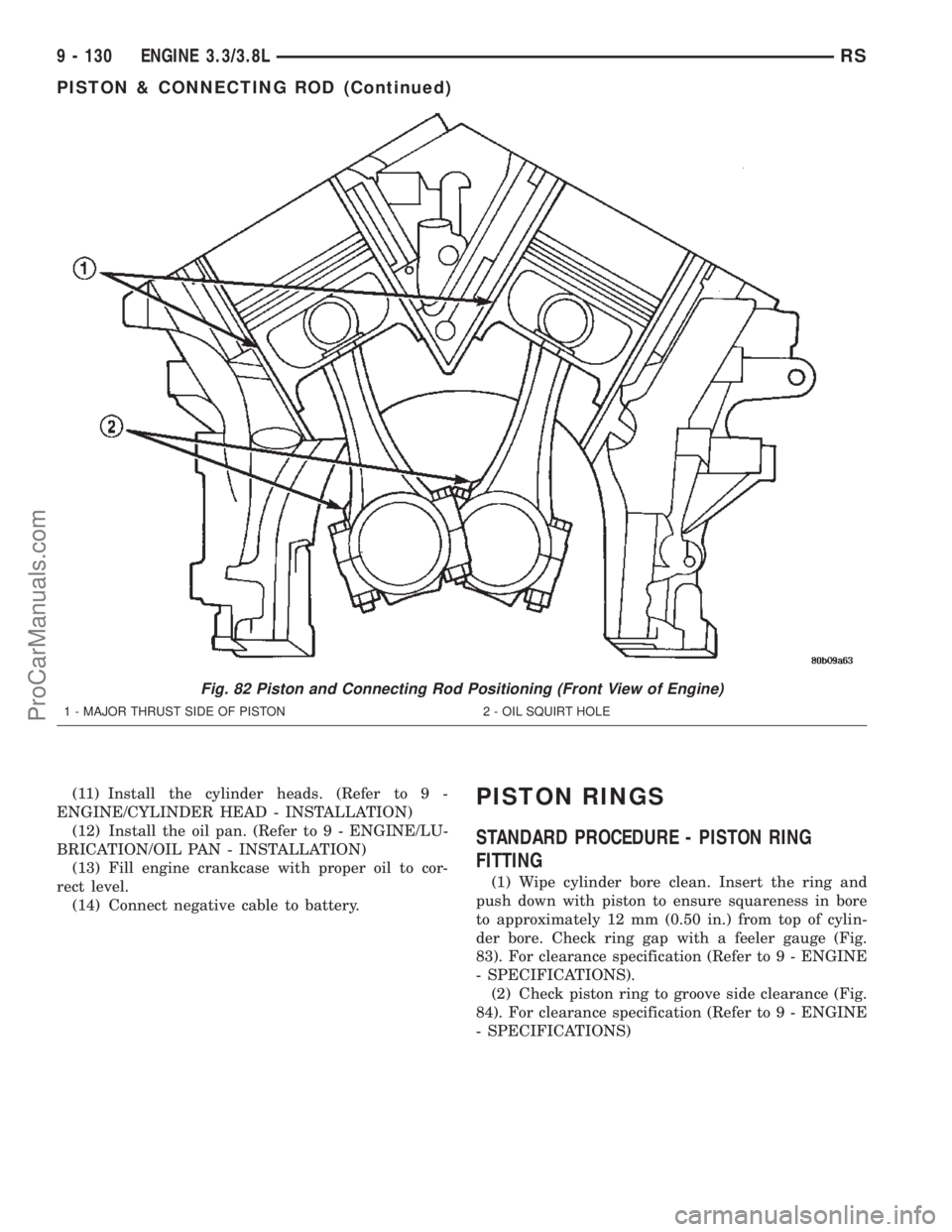
Fig. 82 Piston and Connecting Rod Positioning (Front View of Engine)
1 - MAJOR THRUST SIDE OF PISTON 2 - OIL SQUIRT HOLE
9 - 130 ENGINE 3.3/3.8LRS
PISTON & CONNECTING ROD (Continued)
ProCarManuals.com
Page 1333 of 2399
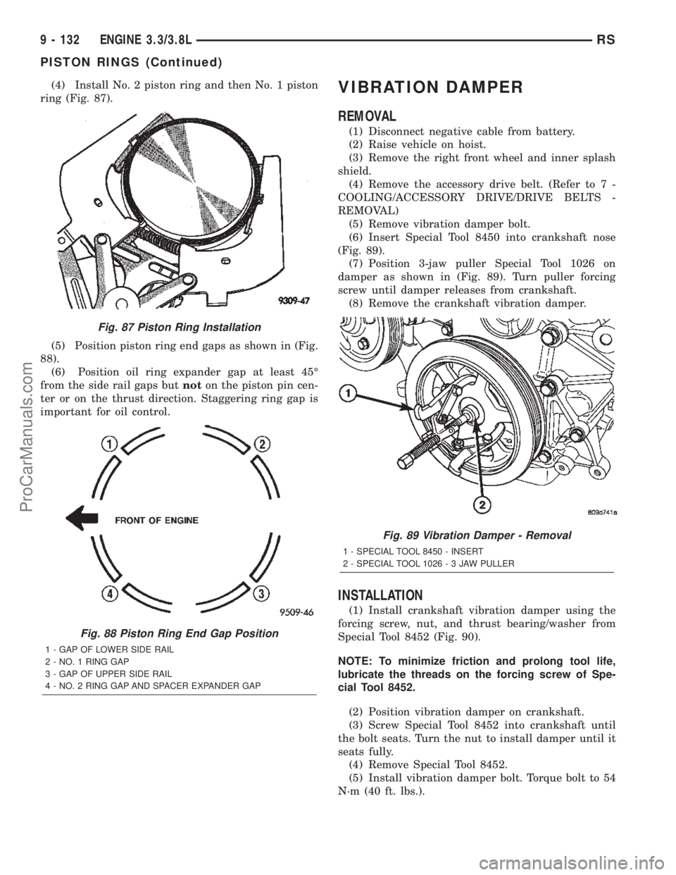
(4) Install No. 2 piston ring and then No. 1 piston
ring (Fig. 87).
(5) Position piston ring end gaps as shown in (Fig.
88).
(6) Position oil ring expander gap at least 45É
from the side rail gaps butnoton the piston pin cen-
ter or on the thrust direction. Staggering ring gap is
important for oil control.VIBRATION DAMPER
REMOVAL
(1) Disconnect negative cable from battery.
(2) Raise vehicle on hoist.
(3) Remove the right front wheel and inner splash
shield.
(4) Remove the accessory drive belt. (Refer to 7 -
COOLING/ACCESSORY DRIVE/DRIVE BELTS -
REMOVAL)
(5) Remove vibration damper bolt.
(6) Insert Special Tool 8450 into crankshaft nose
(Fig. 89).
(7) Position 3-jaw puller Special Tool 1026 on
damper as shown in (Fig. 89). Turn puller forcing
screw until damper releases from crankshaft.
(8) Remove the crankshaft vibration damper.
INSTALLATION
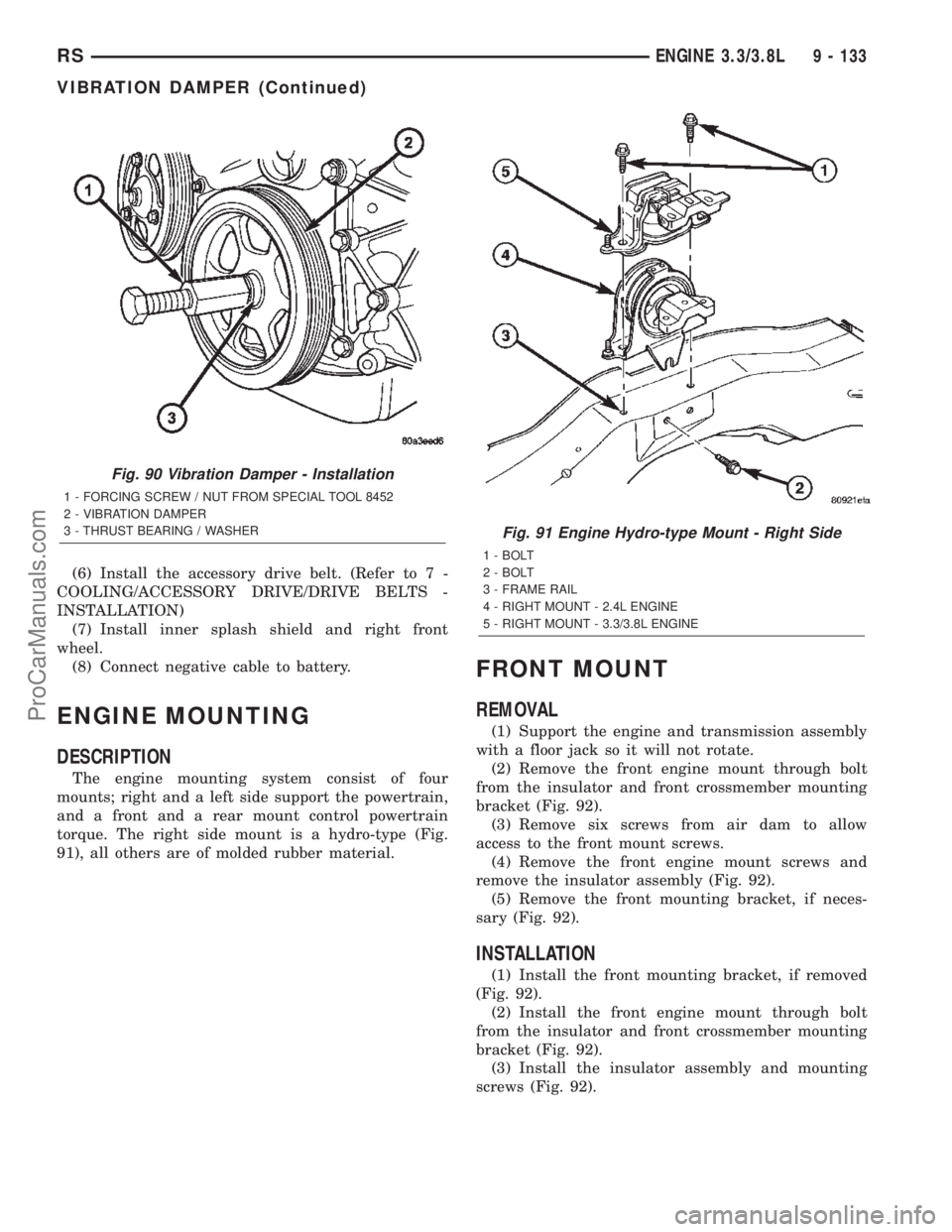
(1) Install crankshaft vibration damper using the
forcing screw, nut, and thrust bearing/washer from
Special Tool 8452 (Fig. 90).
NOTE: To minimize friction and prolong tool life,
lubricate the threads on the forcing screw of Spe-
cial Tool 8452.
(2) Position vibration damper on crankshaft.
(3) Screw Special Tool 8452 into crankshaft until
the bolt seats. Turn the nut to install damper until it
seats fully.
(4) Remove Special Tool 8452.
(5) Install vibration damper bolt. Torque bolt to 54
N´m (40 ft. lbs.).
Fig. 87 Piston Ring Installation
Fig. 88 Piston Ring End Gap Position
1 - GAP OF LOWER SIDE RAIL
2 - NO. 1 RING GAP
3 - GAP OF UPPER SIDE RAIL
4 - NO. 2 RING GAP AND SPACER EXPANDER GAP
Fig. 89 Vibration Damper - Removal
1 - SPECIAL TOOL 8450 - INSERT
2 - SPECIAL TOOL 1026-3JAWPULLER
9 - 132 ENGINE 3.3/3.8LRS
PISTON RINGS (Continued)
ProCarManuals.com
Page 1334 of 2399
(6) Install the accessory drive belt. (Refer to 7 -
COOLING/ACCESSORY DRIVE/DRIVE BELTS -
INSTALLATION)
(7) Install inner splash shield and right front
wheel.
(8) Connect negative cable to battery.
ENGINE MOUNTING
DESCRIPTION
The engine mounting system consist of four
mounts; right and a left side support the powertrain,
and a front and a rear mount control powertrain
torque. The right side mount is a hydro-type (Fig.
91), all others are of molded rubber material.
FRONT MOUNT
REMOVAL
(1) Support the engine and transmission assembly
with a floor jack so it will not rotate.
(2) Remove the front engine mount through bolt
from the insulator and front crossmember mounting
bracket (Fig. 92).
(3) Remove six screws from air dam to allow
access to the front mount screws.
(4) Remove the front engine mount screws and
remove the insulator assembly (Fig. 92).
(5) Remove the front mounting bracket, if neces-
sary (Fig. 92).
INSTALLATION
(1) Install the front mounting bracket, if removed
(Fig. 92).
(2) Install the front engine mount through bolt
from the insulator and front crossmember mounting
bracket (Fig. 92).
(3) Install the insulator assembly and mounting
screws (Fig. 92).
Fig. 90 Vibration Damper - Installation
1 - FORCING SCREW / NUT FROM SPECIAL TOOL 8452
2 - VIBRATION DAMPER
3 - THRUST BEARING / WASHER
Fig. 91 Engine Hydro-type Mount - Right Side
1 - BOLT
2 - BOLT
3 - FRAME RAIL
4 - RIGHT MOUNT - 2.4L ENGINE
5 - RIGHT MOUNT - 3.3/3.8L ENGINE
RSENGINE 3.3/3.8L9 - 133
VIBRATION DAMPER (Continued)
ProCarManuals.com
Page 1342 of 2399
OIL FILTER ADAPTER
REMOVAL
(1) Raise vehicle on hoist.
(2) Remove the oil filter.
(3) Disconnect oil pressure switch electrical con-
nector.
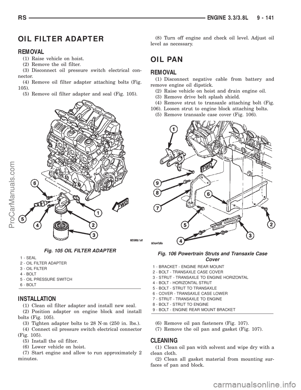
(4) Remove oil filter adapter attaching bolts (Fig.
105).
(5) Remove oil filter adapter and seal (Fig. 105).
INSTALLATION
(1) Clean oil filter adapter and install new seal.
(2) Position adapter on engine block and install
bolts (Fig. 105).
(3) Tighten adapter bolts to 28 N´m (250 in. lbs.).
(4) Connect oil pressure switch electrical connector
(Fig. 105).
(5) Install the oil filter.
(6) Lower vehicle on hoist.
(7) Start engine and allow to run approximately 2
minutes.(8) Turn off engine and check oil level. Adjust oil
level as necessary.
OIL PAN
REMOVAL
(1) Disconnect negative cable from battery and
remove engine oil dipstick.
(2) Raise vehicle on hoist and drain engine oil.
(3) Remove drive belt splash shield.
(4) Remove strut to transaxle attaching bolt (Fig.
106). Loosen strut to engine block attaching bolts.
(5) Remove transaxle case cover (Fig. 106).
(6) Remove oil pan fasteners (Fig. 107).
(7) Remove the oil pan and gasket (Fig. 107).
CLEANING
(1) Clean oil pan with solvent and wipe dry with a
clean cloth.
(2) Clean all gasket material from mounting sur-
faces of pan and block.
Fig. 105 OIL FILTER ADAPTER
1 - SEAL
2 - OIL FILTER ADAPTER
3 - OIL FILTER
4 - BOLT
5 - OIL PRESSURE SWITCH
6 - BOLTFig. 106 Powertrain Struts and Transaxle Case
Cover
1 - BRACKET - ENGINE REAR MOUNT
2 - BOLT - TRANSAXLE CASE COVER
3 - STRUT - TRANSAXLE TO ENGINE HORIZONTAL
4 - BOLT - HORIZONTAL STRUT
5 - BOLT - STRUT TO TRANSAXLE
6 - COVER - TRANSAXLE CASE LOWER
7 - STRUT - TRANSAXLE TO ENGINE
8 - BOLT - STRUT TO ENGINE
9 - BOLT - ENGINE REAR MOUNT BRACKET
RSENGINE 3.3/3.8L9 - 141
ProCarManuals.com
Page 1343 of 2399
(3) Clean oil screen and pick-up tube in clean sol-
vent.
INSPECTION
(1) Inspect oil drain plug and plug hole for
stripped or damaged threads and repair as necessary.
Install a new drain plug gasket. Tighten to 27 N´m
(20 ft. lbs.).
(2) Inspect oil pan mounting flange for bends or
distortion. Straighten flange if necessary.
(3) Inspect condition of oil screen and pick-up tube.
INSTALLATION
(1) Clean sealing surfaces and apply a 1/8 inch
bead of MopartEngine RTV GEN II at the parting
line of the chain case cover and the rear seal retainer
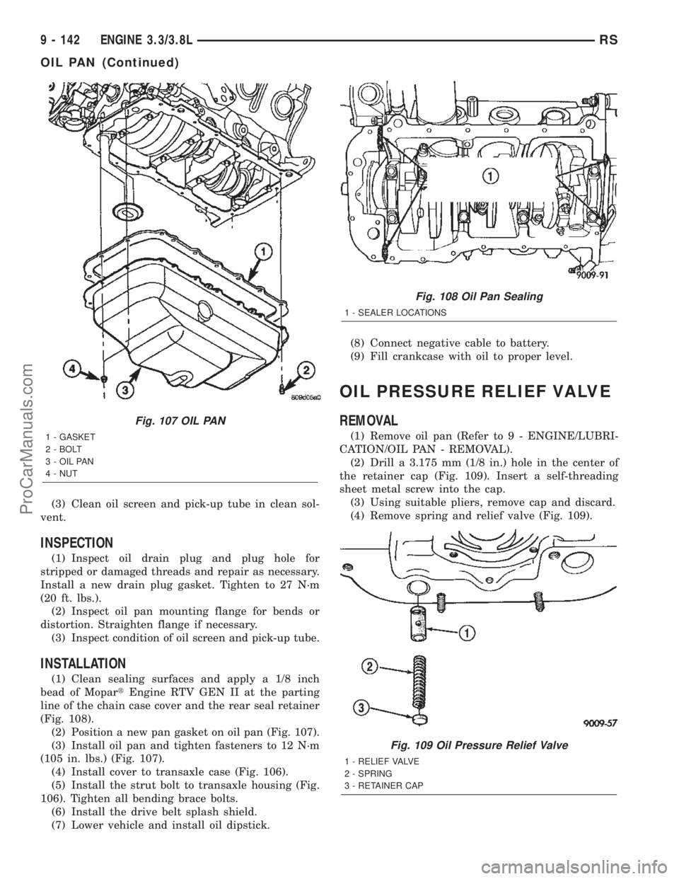
(Fig. 108).
(2) Position a new pan gasket on oil pan (Fig. 107).
(3) Install oil pan and tighten fasteners to 12 N´m
(105 in. lbs.) (Fig. 107).
(4) Install cover to transaxle case (Fig. 106).
(5) Install the strut bolt to transaxle housing (Fig.
106). Tighten all bending brace bolts.
(6) Install the drive belt splash shield.
(7) Lower vehicle and install oil dipstick.(8) Connect negative cable to battery.
(9) Fill crankcase with oil to proper level.
OIL PRESSURE RELIEF VALVE
REMOVAL
(1) Remove oil pan (Refer to 9 - ENGINE/LUBRI-
CATION/OIL PAN - REMOVAL).
(2) Drill a 3.175 mm (1/8 in.) hole in the center of
the retainer cap (Fig. 109). Insert a self-threading
sheet metal screw into the cap.
(3) Using suitable pliers, remove cap and discard.
(4) Remove spring and relief valve (Fig. 109).
Fig. 107 OIL PAN
1 - GASKET
2 - BOLT
3 - OIL PAN
4 - NUT
Fig. 108 Oil Pan Sealing
1 - SEALER LOCATIONS
Fig. 109 Oil Pressure Relief Valve
1 - RELIEF VALVE
2 - SPRING
3 - RETAINER CAP
9 - 142 ENGINE 3.3/3.8LRS
OIL PAN (Continued)
ProCarManuals.com
Page 1348 of 2399
repair screw available through Mopartparts. Repair
screws are available for the following manifold
attached components:
²MAP sensor
²Power steering reservoir
²EGR tube
²Throttle cable bracket
The repair screws require a unique tightening
torque specification from the original screw. Refer to
the following chart for specification.
DESCRIPTION TORQUE*
STRIP-OUT REPAIR SCREWS ONLY
MAP Sensor Repair
Screw4 N´m (35 in. lbs.)
Power Steering Reservoir
Repair Screw9 N´m (80 in. lbs.)
EGR Tube Attaching
Repair Screw9 N´m (80 in. lbs.)
Throttle Cable Bracket
Repair Screw9 N´m (80 in. lbs.)
*Install Slowly Using Hand Tools Only
STANDARD PROCEDURE - INTAKE MANIFOLD
VACUUM PORT REPAIR
The composite intake manifold vacuum ports can
be repaired. Although, if the manifold plenum cham-
ber is damaged or cracked, the manifold must be
replaced.
To repair a broken or damaged vacuum nipple
(port) on the composite intake manifold, perform the
following procedure:
PARTS REQUIRED TOOLS REQUIRED
´ Brass Nipple ± 1/49
O.D. x 1/89pipe thread
(LDP/Speed Control Port)´ Pipe Tap ± 1/89-18
NPT
´ Drill Bit ± 11/329
´ File/Sandpaper
´ Brass Nipple ± 1/29
O.D. x 1/49pipe thread
(Brake Booster Port)´ Pipe Tap ± 1/49-18
NPT
´ Drill Bit ± 7/169
´ File/Sandpaper
NOTE: While performing this procedure, avoid get-
ting the manifold material residue into the plenum
chamber.
(1) File or sand the remaining port back until a
flat surface is obtained (plane normal to nipple (port)
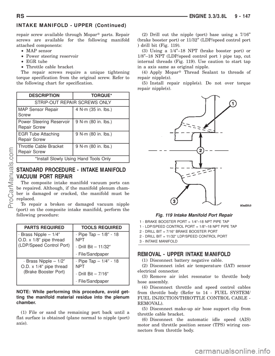
axis).(2) Drill out the nipple (port) base using a 7/16º
(brake booster port) or 11/32º (LDP/speed control port
) drill bit (Fig. 119).
(3) Using a 1/4º±18 NPT (brake booster port) or
1/8º±18 NPT (LDP/speed control port ) pipe tap, cut
internal threads (Fig. 119). Use caution to start tap
in a axis same as original nipple.
(4) Apply MopartThread Sealant to threads of
repair nipple(s).
(5) Install repair nipple(s). Do not over torque
repair nipple(s).
REMOVAL - UPPER INTAKE MANIFOLD
(1) Disconnect battery negative cable.
(2) Disconnect inlet air temperature (IAT) sensor
electrical connector.
(3) Remove air inlet resonator to throttle body
hose assembly.
(4) Disconnect throttle and speed control cables
from throttle body (Refer to 14 - FUEL SYSTEM/
FUEL INJECTION/THROTTLE CONTROL CABLE -
REMOVAL).
(5) Disconnect make-up air hose support clip from
throttle cable bracket.
(6) Disconnect the automatic idle speed (AIS)
motor and throttle position sensor (TPS) wiring con-
nectors from throttle body.
Fig. 119 Intake Manifold Port Repair
1 - BRAKE BOOSTER PORT = 1/49±18 NPT PIPE TAP
1 - LDP/SPEED CONTROL PORT = 1/89±18 NPT PIPE TAP
2 - DRILL BIT = 7/169BRAKE BOOSTER PORT
2 - DRILL BIT = 11/329LDP/SPEED CONTROL PORT
3 - INTAKE MANIFOLD
RSENGINE 3.3/3.8L9 - 147
INTAKE MANIFOLD - UPPER (Continued)
ProCarManuals.com
Page 1351 of 2399
(11) Install air cleaner and air inlet hose assembly.
(12) Connect the inlet air temperature (IAT) sen-
sor electrical connector.
(13) Connect battery negative cable.
INTAKE MANIFOLD - LOWER
REMOVAL - LOWER INTAKE MANIFOLD
(1) Perform fuel system pressure release procedure
(before attempting any repairs).(Refer to 14 -
FUEL SYSTEM/FUEL DELIVERY - STANDARD
PROCEDURE)
(2) Drain the cooling system. (Refer to 7 - COOL-
ING - STANDARD PROCEDURE)
(3) Remove the upper intake manifold. (Refer to 9
- ENGINE/MANIFOLDS/INTAKE MANIFOLD -
REMOVAL)
(4) Remove the fuel line. (Refer to 14 - FUEL SYS-
TEM/FUEL DELIVERY/FUEL LINES - STANDARD
PROCEDURE) (Refer to 14 - FUEL SYSTEM/FUEL
DELIVERY/QUICK CONNECT FITTING - STAN-
DARD PROCEDURE)
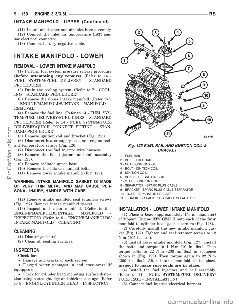
(5) Remove ignition coil and bracket (Fig. 125).
(6) Disconnect heater supply hose and engine cool-
ant temperature sensor (Fig. 126).
(7) Disconnect the fuel injector wire harness.
(8) Remove the fuel injectors and rail assembly
(Fig. 125).
(9) Remove radiator upper hose.
(10) Remove the intake manifold bolts.
(11) Remove lower intake manifold (Fig. 127).
WARNING: INTAKE MANIFOLD GASKET IS MADE
OF VERY THIN METAL AND MAY CAUSE PER-
SONAL INJURY, HANDLE WITH CARE.
(12) Remove intake manifold seal retainers screws
(Fig. 127). Remove intake manifold gasket.
(13) Inspect and clean manifold. (Refer to 9 -
ENGINE/MANIFOLDS/INTAKE MANIFOLD -
INSPECTION) (Refer to 9 - ENGINE/MANIFOLDS/
INTAKE MANIFOLD - CLEANING)
CLEANING
(1) Discard gasket(s).
(2) Clean all sealing surfaces.
INSPECTION
Check for:
²Damage and cracks of each section.
²Clogged water passages in end cross-overs (if
equipped).
²Check for cylinder head mounting surface distor-
tion using a straightedge and thickness gauge. (Refer
to 9 - ENGINE/CYLINDER HEAD - INSPECTION)
INSTALLATION - LOWER INTAKE MANIFOLD
(1) Place a bead (approximately 1/4 in. diameter)
of MopartEngine RTV GEN II onto each of thefour
manifold to cylinder head gasket corners (Fig. 128).
(2) Carefully install the new intake manifold gas-
ket (Fig. 127). Tighten end seal retainer screws to 12
N´m (105 in. lbs.).
(3) Install lower intake manifold (Fig. 127). Install
the bolts and torque to 1 N´m (10 in. lbs.). Then
torque bolts to 22 N´m (200 in. lbs.) in sequence
shown in (Fig. 129). Then torque again to 22 N´m
(200 in. lbs.). After intake manifold is in place,
inspect to make sure seals are in place.
(4) Install the fuel injectors and rail assembly.
(Refer to 14 - FUEL SYSTEM/FUEL DELIVERY/
FUEL RAIL - INSTALLATION)
(5) Connect fuel injector electrical harness.
Fig. 125 FUEL RAIL AND IGNITION COIL &
BRACKET
1 - FUEL RAIL
2 - BOLT - FUEL RAIL
3 - NUT - IGNITION COIL
4 - BOLT - IGNITION COIL
5 - IGNITION COIL
6 - BRACKET - IGNITION COIL
7 - STUD - IGNITION COIL
8 - SEPARATOR - SPARK PLUG CABLE
9 - BRACKET - SPARK PLUG CABLE SEPARATOR
10 - BOLT - SEPARATOR BRACKET
11 - BRACKET - SPARK PLUG CABLE SEPARATOR
9 - 150 ENGINE 3.3/3.8LRS
INTAKE MANIFOLD - UPPER (Continued)
ProCarManuals.com
Page 1352 of 2399
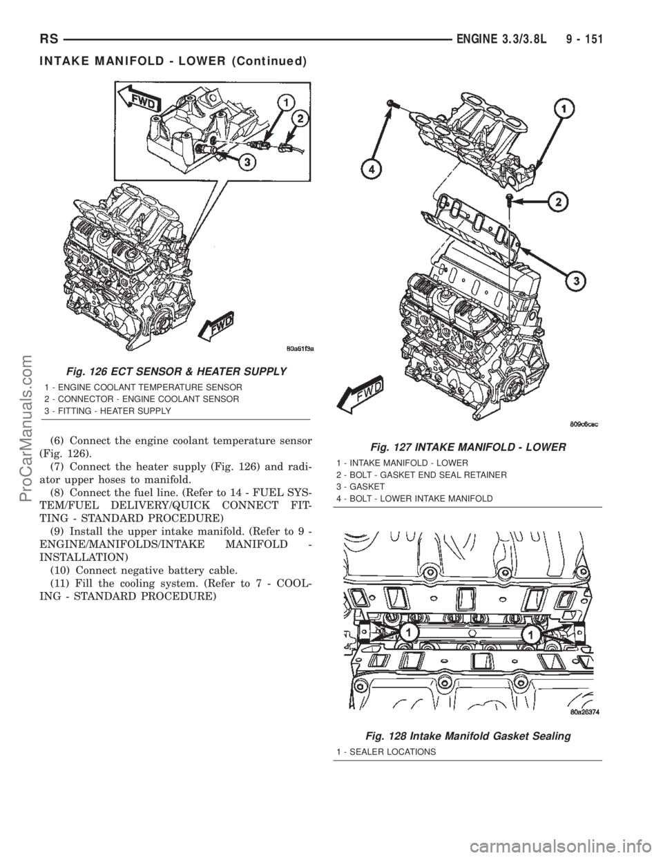
(6) Connect the engine coolant temperature sensor
(Fig. 126).
(7) Connect the heater supply (Fig. 126) and radi-
ator upper hoses to manifold.
(8) Connect the fuel line. (Refer to 14 - FUEL SYS-
TEM/FUEL DELIVERY/QUICK CONNECT FIT-
TING - STANDARD PROCEDURE)
(9) Install the upper intake manifold. (Refer to 9 -
ENGINE/MANIFOLDS/INTAKE MANIFOLD -
INSTALLATION)
(10) Connect negative battery cable.
(11) Fill the cooling system. (Refer to 7 - COOL-
ING - STANDARD PROCEDURE)
Fig. 126 ECT SENSOR & HEATER SUPPLY
1 - ENGINE COOLANT TEMPERATURE SENSOR
2 - CONNECTOR - ENGINE COOLANT SENSOR
3 - FITTING - HEATER SUPPLY
Fig. 127 INTAKE MANIFOLD - LOWER
1 - INTAKE MANIFOLD - LOWER
2 - BOLT - GASKET END SEAL RETAINER
3 - GASKET
4 - BOLT - LOWER INTAKE MANIFOLD
Fig. 128 Intake Manifold Gasket Sealing
1 - SEALER LOCATIONS
RSENGINE 3.3/3.8L9 - 151
INTAKE MANIFOLD - LOWER (Continued)
ProCarManuals.com