2002 CHRYSLER CARAVAN checking oil
[x] Cancel search: checking oilPage 1340 of 2399

(9) Lower vehicle and fill crankcase with specified
type and amount of engine oil. (Refer to LUBRICA-
TION & MAINTENANCE/FLUID TYPES -
DESCRIPTION)
(10) Install oil fill cap.
(11) Start engine and inspect for leaks.
(12) Stop engine and inspect oil level.
NOTE: Care should be exercised when disposing
used engine oil after it has been drained from a
vehicle engine. Refer to the WARNING listed above.
STANDARD PROCEDURE - ENGINE OIL LEVEL
CHECK
The best time to check engine oil level is after it
has sat overnight, or if the engine has been running,
allow the engine to be shut off for at least 5 minutes
before checking oil level.
Checking the oil while the vehicle is on level
ground will improve the accuracy of the oil level
reading (Fig. 102). Add only when the level is at or
below the ADD mark.
Fig. 102 Engine Oil Level Dipstick and Fill Locations
1 - COOLANT RECOVERY CONTAINER 3 - ENGINE OIL LEVEL DIPSTICK
2 - ENGINE OIL FILL CAP 4 - RADIATOR PRESSURE CAP
Fig. 101 Engine Oil Drain Plug and Oil Filter
1 - DRAIN PLUG
2 - OIL FILTER
RSENGINE 3.3/3.8L9 - 139
OIL (Continued)
ProCarManuals.com
Page 1345 of 2399
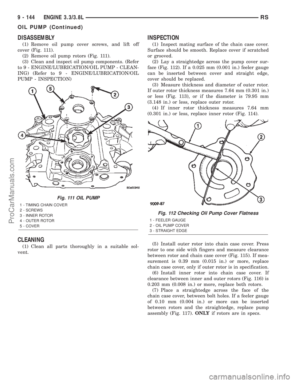
DISASSEMBLY
(1) Remove oil pump cover screws, and lift off
cover (Fig. 111).
(2) Remove oil pump rotors (Fig. 111).
(3) Clean and inspect oil pump components. (Refer
to 9 - ENGINE/LUBRICATION/OIL PUMP - CLEAN-
ING) (Refer to 9 - ENGINE/LUBRICATION/OIL
PUMP - INSPECTION)
CLEANING
(1) Clean all parts thoroughly in a suitable sol-
vent.
INSPECTION
(1) Inspect mating surface of the chain case cover.
Surface should be smooth. Replace cover if scratched
or grooved.
(2) Lay a straightedge across the pump cover sur-
face (Fig. 112). If a 0.025 mm (0.001 in.) feeler gauge
can be inserted between cover and straight edge,
cover should be replaced.
(3) Measure thickness and diameter of outer rotor.
If outer rotor thickness measures 7.64 mm (0.301 in.)
or less (Fig. 113), or if the diameter is 79.95 mm
(3.148 in.) or less, replace outer rotor.
(4) If inner rotor thickness measures 7.64 mm
(0.301 in.) or less, replace inner rotor (Fig. 114).
(5) Install outer rotor into chain case cover. Press
rotor to one side with fingers and measure clearance
between rotor and chain case cover (Fig. 115). If mea-
surement is 0.39 mm (0.015 in.) or more, replace
chain case cover, only if outer rotor is in specification.
(6) Install inner rotor into chain case cover. If
clearance between inner and outer rotors (Fig. 116) is
0.203 mm (0.008 in.) or more, replace both rotors.
(7) Place a straightedge across the face of the
chain case cover, between bolt holes. If a feeler gauge
of 0.10 mm (0.004 in.) or more can be inserted
between rotors and the straightedge, replace pump
assembly (Fig. 117).ONLYif rotors are in specs.
Fig. 111 OIL PUMP
1 - TIMING CHAIN COVER
2 - SCREWS
3 - INNER ROTOR
4 - OUTER ROTOR
5 - COVER
Fig. 112 Checking Oil Pump Cover Flatness
1 - FEELER GAUGE
2 - OIL PUMP COVER
3 - STRAIGHT EDGE
9 - 144 ENGINE 3.3/3.8LRS
OIL PUMP (Continued)
ProCarManuals.com
Page 1362 of 2399
ENGINE
TABLE OF CONTENTS
page page
ENGINE 2.5L TURBO DIESEL
DESCRIPTION
DESCRIPTION - 2.5L COMMON RAIL
DIESEL ENGINE.......................2
DESCRIPTION - ENGINE COVER..........3
REMOVAL
REMOVAL - 2.5L DIESEL ENGINE..........3
REMOVAL - ENGINE COVER.............6
INSTALLATION
INSTALLATION - 2.5L TURBO DIESEL
ENGINE..............................7
INSTALLATION - ENGINE COVER..........7
SPECIFICATIONS
SPECIFICATIONS - 2.5L COMMON RAIL
DIESEL ENGINE.......................8
SPECIFICATIONS - TORQUE............10
SPECIAL TOOLS.......................12
CYLINDER HEAD
STANDARD PROCEDURE
STANDARD PROCEDURE - VALVE
SERVICE............................17
STANDARD PROCEDURE - MEASURING
PISTON PROTRUSION.................18
REMOVAL.............................19
CLEANING............................21
INSPECTION..........................21
INSTALLATION.........................21
CAMSHAFT(S)
DESCRIPTION.........................22
OPERATION...........................22
REMOVAL.............................22
INSTALLATION.........................23
CYLINDER HEAD COVER(S)
DESCRIPTION.........................24
REMOVAL.............................24
INSTALLATION.........................25
CAMSHAFT OIL SEAL(S)
REMOVAL.............................27
INSTALLATION.........................27
ROCKER ARMS
DESCRIPTION.........................27
OPERATION...........................27
REMOVAL.............................27
INSTALLATION.........................28
HYDRAULIC LIFTERS
DESCRIPTION.........................29
REMOVAL.............................29
INSPECTION..........................30
INSTALLATION.........................30ENGINE BLOCK
DESCRIPTION.........................30
CRANKSHAFT
DESCRIPTION.........................30
OPERATION...........................30
STANDARD PROCEDURE - CHECKING
CRANKSHAFT END PLAY...............31
REMOVAL.............................31
INSTALLATION.........................32
CYLINDER LINERS
DESCRIPTION.........................33
REMOVAL.............................33
INSPECTION..........................34
INSTALLATION.........................34
INTERNAL VACUUM PUMP
DESCRIPTION.........................35
REMOVAL.............................35
INSTALLATION.........................35
PISTON & CONNECTING ROD
DESCRIPTION.........................36
STANDARD PROCEDURE - PISTON RING
FITTING.............................36
REMOVAL.............................36
INSPECTION..........................38
INSTALLATION.........................39
CRANKSHAFT OIL SEAL - FRONT
REMOVAL.............................41
INSTALLATION.........................41
VIBRATION DAMPER
REMOVAL.............................42
INSTALLATION.........................42
ENGINE COVER - FRONT
DESCRIPTION.........................43
REMOVAL.............................43
INSTALLATION.........................43
CRANKSHAFT MAIN BEARINGS
REMOVAL.............................44
INSTALLATION.........................45
CRANKSHAFT OIL SEAL - REAR
REMOVAL.............................46
INSTALLATION.........................46
OIL PAN
REMOVAL.............................46
INSTALLATION.........................46
OIL PUMP
REMOVAL
REMOVAL...........................47
REMOVAL...........................47
RGENGINE9a-1
ProCarManuals.com
Page 1384 of 2399
CAUTION: Before removing the cylinder head cover/
intake manifold or timing belt the engine must put
at 90É after TDC. Failure to do so could result in
valve and/or piston damage during reassembly.
(Refer to 9 - ENGINE/VALVE TIMING - STANDARD
PROCEDURE)
(10) Remove timing belt outer cover (Refer to 9 -
ENGINE/VALVE TIMING/TIMING BELT / CHAIN
COVER(S) - REMOVAL).
(11) Remove timing belt (Refer to 9 - ENGINE/
VALVE TIMING/TIMING BELT/CHAIN AND
SPROCKETS - REMOVAL).
(12) Remove timing belt inner cover (Refer to 9 -
ENGINE/VALVE TIMING/TIMING BELT / CHAIN
COVER(S) - REMOVAL).
(13) Remove cylinder head cover/intake manifold
(Refer to 9 - ENGINE/CYLINDER HEAD/CYLIN-
DER HEAD COVER(S) - REMOVAL).
(14) With cylinder head cover/intake manifold on
work bench, remove plugs at rear of cylinder head
cover/intake manifold.
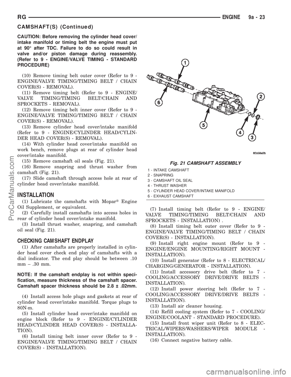
(15) Remove camshaft oil seals (Fig. 21).
(16) Remove snapring and thrust washer from
camshaft (Fig. 21).
(17) Slide camshaft through access hole at rear of
cylinder head cover/intake manifold.
INSTALLATION
(1) Lubricate the camshafts with MopartEngine
Oil Supplement, or equivalent.
(2) Carefully install camshafts into access holes in
rear of cylinder head cover/intake manifold.
(3) Install thrust washer, snapring, and camshaft
oil seal (Fig. 21).
CHECKING CAMSHAFT ENDPLAY
(1) After camshafts are properly installed in cylin-
der head cover check end play of camshafts with a
dial indicator. The end play should be between .10
mm ± .30 mm.
NOTE: If the camshaft endplay is not within speci-
fication, measure thickness of the camshaft spacer.
Camshaft spacer thickness should be 2.8 .02mm.
(4) Install access hole plugs and gaskets at rear of
cylinder head cover/intake manifold. Torque plugs to
80N´m.
(5) Install cylinder head cover/intake manifold on
engine block (Refer to 9 - ENGINE/CYLINDER
HEAD/CYLINDER HEAD COVER(S) - INSTALLA-
TION).
(6) Install timing belt inner cover (Refer to 9 -
ENGINE/VALVE TIMING/TIMING BELT / CHAIN
COVER(S) - INSTALLATION).(7) Install timing belt (Refer to 9 - ENGINE/
VALVE TIMING/TIMING BELT/CHAIN AND
SPROCKETS - INSTALLATION) .
(8) Install timing belt outer cover (Refer to 9 -
ENGINE/VALVE TIMING/TIMING BELT / CHAIN
COVER(S) - INSTALLATION).
(9) Install right engine mount (Refer to 9 -
ENGINE/ENGINE MOUNTING/RIGHT MOUNT -
INSTALLATION).
(10) Install generator (Refer to 8 - ELECTRICAL/
CHARGING/GENERATOR - INSTALLATION).
(11) Install accessory drive belt (Refer to 7 -
COOLING/ACCESSORY DRIVE/DRIVE BELTS -
INSTALLATION).
(12) Install power steering belt (Refer to 7 -
COOLING/ACCESSORY DRIVE/DRIVE BELTS -
INSTALLATION).
(13) Install air cleaner housing.
(14) Refill cooling system (Refer to 7 - COOLING/
ENGINE/COOLANT - STANDARD PROCEDURE).
(15) Install front wiper unit (Refer to 8 - ELEC-
TRICAL/WIPERS/WASHERS/WIPER MODULE -
INSTALLATION).
(16) Connect negative battery cable.
Fig. 21 CAMSHAFT ASSEMBLY
1 - INTAKE CAMSHAFT
2 - SNAPRING
3 - CAMSHAFT OIL SEAL
4 - THRUST WASHER
5 - CYLINDER HEAD COVER/INTAKE MANIFOLD
6 - EXHAUST CAMSHAFT
RGENGINE9a-23
CAMSHAFT(S) (Continued)
ProCarManuals.com
Page 1392 of 2399
STANDARD PROCEDURE - CHECKING
CRANKSHAFT END PLAY
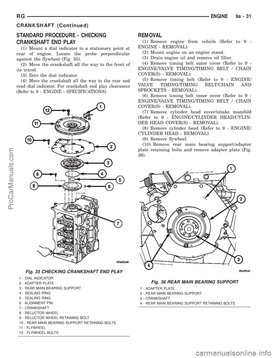
(1) Mount a dial indicator to a stationary point at
rear of engine. Locate the probe perpendicular
against the flywheel (Fig. 35).
(2) Move the crankshaft all the way to the front of
its travel.
(3) Zero the dial indicator.
(4)
Move the crankshaft all the way to the rear and
read dial indicator. For crankshaft end play clearances
(Refer to 9 - ENGINE - SPECIFICATIONS).
REMOVAL
(1) Remove engine from vehicle (Refer to 9 -
ENGINE - REMOVAL).
(2) Mount engine on an engine stand.
(3) Drain engine oil and remove oil filter.
(4) Remove timing belt outer cover (Refer to 9 -
ENGINE/VALVE TIMING/TIMING BELT / CHAIN
COVER(S) - REMOVAL).
(5) Remove timing belt (Refer to 9 - ENGINE/
VALVE TIMING/TIMING BELT/CHAIN AND
SPROCKETS - REMOVAL).
(6) Remove timing belt inner cover (Refer to 9 -
ENGINE/VALVE TIMING/TIMING BELT / CHAIN
COVER(S) - REMOVAL).
(7) Remove cylinder head cover/intake manifold
(Refer to 9 - ENGINE/CYLINDER HEAD/CYLIN-
DER HEAD COVER(S) - REMOVAL).
(8) Remove cylinder head (Refer to 9 - ENGINE/
CYLINDER HEAD - REMOVAL).
(9) Remove flywheel.
(10) Remove rear main bearing support/adapter
plate retaining bolts and remove adapter plate (Fig.
36).
Fig. 35 CHECKING CRANKSHAFT END PLAY
1 - DIAL INDICATOR
2 - ADAPTER PLATE
3 - REAR MAIN BEARING SUPPORT
4 - SEALING RING
5 - SEALING RING
6 - ALIGNMENT PIN
7 - CRANKSHAFT
8 - RELUCTOR WHEEL
9 - RELUCTOR WHEEL RETAINING BOLT
10 - REAR MAIN BEARING SUPPORT RETAINING BOLTS
11 - FLYWHEEL
12 - FLYWHEEL BOLTSFig. 36 REAR MAIN BEARING SUPPORT
1 - ADAPTER PLATE
2 - REAR MAIN BEARING SUPPORT
3 - CRANKSHAFT
4 - REAR MAIN BEARING SUPPORT RETAINING BOLTS
RGENGINE9a-31
CRANKSHAFT (Continued)
ProCarManuals.com
Page 1655 of 2399
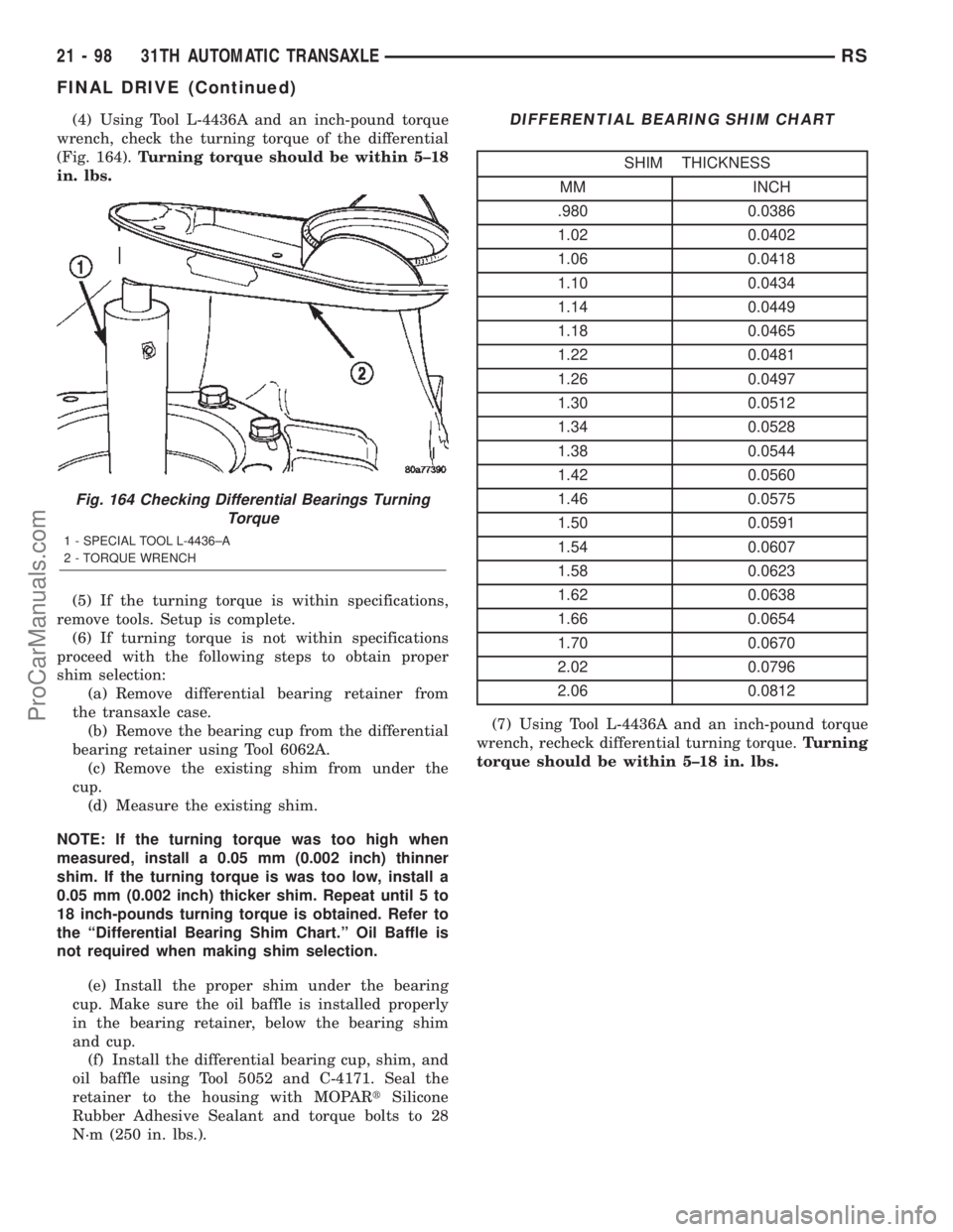
(4) Using Tool L-4436A and an inch-pound torque
wrench, check the turning torque of the differential
(Fig. 164).Turning torque should be within 5±18
in. lbs.
(5) If the turning torque is within specifications,
remove tools. Setup is complete.
(6) If turning torque is not within specifications
proceed with the following steps to obtain proper
shim selection:
(a) Remove differential bearing retainer from
the transaxle case.
(b) Remove the bearing cup from the differential
bearing retainer using Tool 6062A.
(c) Remove the existing shim from under the
cup.
(d) Measure the existing shim.
NOTE: If the turning torque was too high when
measured, install a 0.05 mm (0.002 inch) thinner
shim. If the turning torque is was too low, install a
0.05 mm (0.002 inch) thicker shim. Repeat until 5 to
18 inch-pounds turning torque is obtained. Refer to
the ªDifferential Bearing Shim Chart.º Oil Baffle is
not required when making shim selection.
(e) Install the proper shim under the bearing
cup. Make sure the oil baffle is installed properly
in the bearing retainer, below the bearing shim
and cup.
(f) Install the differential bearing cup, shim, and
oil baffle using Tool 5052 and C-4171. Seal the
retainer to the housing with MOPARtSilicone
Rubber Adhesive Sealant and torque bolts to 28
N´m (250 in. lbs.).DIFFERENTIAL BEARING SHIM CHART
SHIM THICKNESS
MM INCH
.980 0.0386
1.02 0.0402
1.06 0.0418
1.10 0.0434
1.14 0.0449
1.18 0.0465
1.22 0.0481
1.26 0.0497
1.30 0.0512
1.34 0.0528
1.38 0.0544
1.42 0.0560
1.46 0.0575
1.50 0.0591
1.54 0.0607
1.58 0.0623
1.62 0.0638
1.66 0.0654
1.70 0.0670
2.02 0.0796
2.06 0.0812
(7) Using Tool L-4436A and an inch-pound torque
wrench, recheck differential turning torque.Turning
torque should be within 5±18 in. lbs.
Fig. 164 Checking Differential Bearings Turning
Torque
1 - SPECIAL TOOL L-4436±A
2 - TORQUE WRENCH
21 - 98 31TH AUTOMATIC TRANSAXLERS
FINAL DRIVE (Continued)
ProCarManuals.com
Page 1804 of 2399

(3) Rotate the differential at least one full revolu-
tion to ensure the tapered roller bearings are fully
seated.
(4) Using Tool L-4436A and an inch-pound torque
wrench, check the turning torque of the differential
(Fig. 209).The turning torque should be
between 5 and 18 inch-pounds.
(5) If the turning torque is within specifications,
remove tools. Setup is complete.
(6) If turning torque is not within specifications
proceed with the following steps.(a) Remove differential bearing retainer from
the transaxle case.
(b) Remove the bearing cup from the differential
bearing retainer using Tool 6062A.
(c) Remove the existing shim from under the
cup.
(d) Measure the existing shim.
(e) If the turning torque was too high when mea-
sured, install a 0.05 mm (0.002 inch) thinner shim.
If the turning torque is was too low, install a 0.05
mm (0.002 inch) thicker shim. Repeat until 5-18
inch-pounds turning torque is obtained. Oil Baffle
is not required to be installed when making shim
selection.
(f) Install the proper shim under the bearing
cup. Make sure the oil baffle is installed properly
in the bearing retainer, below the bearing shim
and cup.
(g) Install the differential bearing retainer using
Tool 5052 and C-4171. Seal the retainer to the
housing with MOPARtSilicone Rubber Adhesive
Sealant and torque bolts to 28 N´m (250 in. lbs.).
(7) Using Tool L-4436A and an inch-pound torque
wrench, recheck the turning torque of the differential
(Fig. 209).The turning torque should be within
5-18 inch-pounds.
Shim thickness need be determined only if any of
the following parts are replaced:
²Transaxle case
²Differential carrier
²Differential bearing retainer
²Extension housing
²Differential bearing cups and cones
Fig. 209 Checking Differential Bearings Turning
Torque
1 - SPECIAL TOOL L-4436±A
2 - TORQUE WRENCH
RS41TE AUTOMATIC TRANSAXLE21 - 247
FINAL DRIVE (Continued)
ProCarManuals.com
Page 1829 of 2399
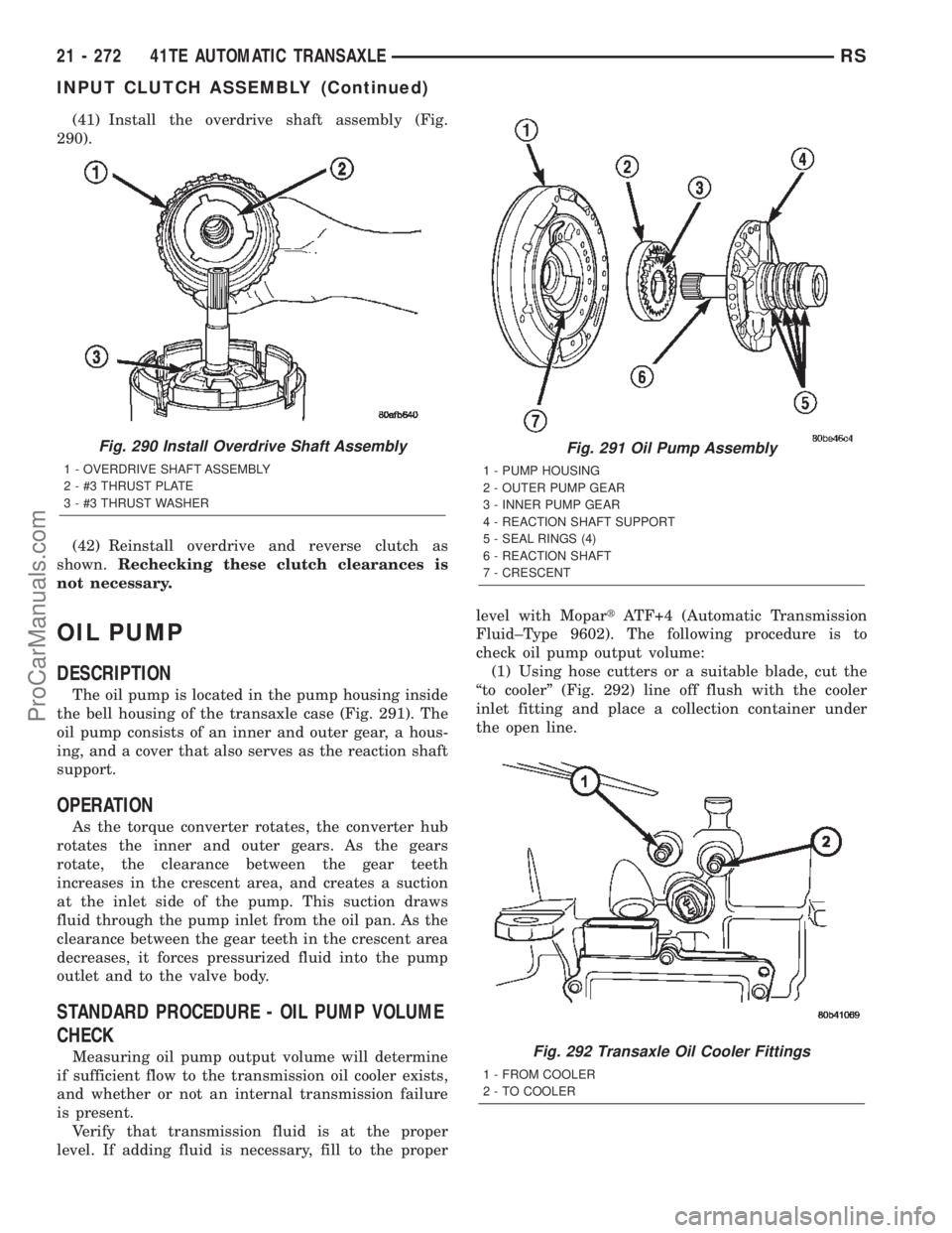
(41) Install the overdrive shaft assembly (Fig.
290).
(42) Reinstall overdrive and reverse clutch as
shown.Rechecking these clutch clearances is
not necessary.
OIL PUMP
DESCRIPTION
The oil pump is located in the pump housing inside
the bell housing of the transaxle case (Fig. 291). The
oil pump consists of an inner and outer gear, a hous-
ing, and a cover that also serves as the reaction shaft
support.
OPERATION
As the torque converter rotates, the converter hub
rotates the inner and outer gears. As the gears
rotate, the clearance between the gear teeth
increases in the crescent area, and creates a suction
at the inlet side of the pump. This suction draws
fluid through the pump inlet from the oil pan. As the
clearance between the gear teeth in the crescent area
decreases, it forces pressurized fluid into the pump
outlet and to the valve body.
STANDARD PROCEDURE - OIL PUMP VOLUME
CHECK
Measuring oil pump output volume will determine
if sufficient flow to the transmission oil cooler exists,
and whether or not an internal transmission failure
is present.
Verify that transmission fluid is at the proper
level. If adding fluid is necessary, fill to the properlevel with MopartATF+4 (Automatic Transmission
Fluid±Type 9602). The following procedure is to
check oil pump output volume:
(1) Using hose cutters or a suitable blade, cut the
ªto coolerº (Fig. 292) line off flush with the cooler
inlet fitting and place a collection container under
the open line.
Fig. 290 Install Overdrive Shaft Assembly
1 - OVERDRIVE SHAFT ASSEMBLY
2 - #3 THRUST PLATE
3 - #3 THRUST WASHER
Fig. 291 Oil Pump Assembly
1 - PUMP HOUSING
2 - OUTER PUMP GEAR
3 - INNER PUMP GEAR
4 - REACTION SHAFT SUPPORT
5 - SEAL RINGS (4)
6 - REACTION SHAFT
7 - CRESCENT
Fig. 292 Transaxle Oil Cooler Fittings
1 - FROM COOLER
2 - TO COOLER
21 - 272 41TE AUTOMATIC TRANSAXLERS
INPUT CLUTCH ASSEMBLY (Continued)
ProCarManuals.com