2002 CHRYSLER CARAVAN checking oil
[x] Cancel search: checking oilPage 1258 of 2399
CLEANING
(1) Clean all parts thoroughly in a suitable sol-
vent.
INSPECTION
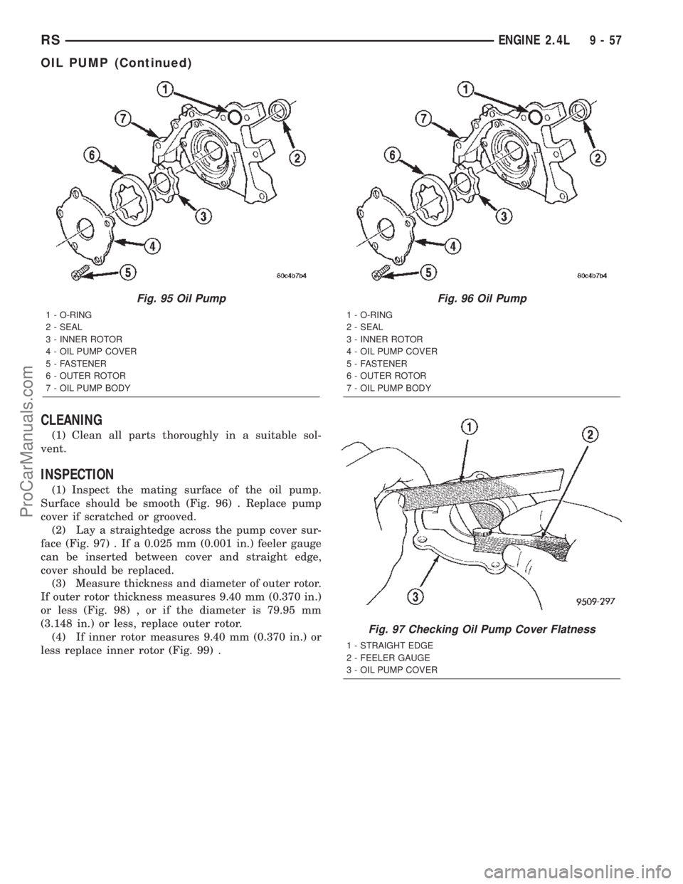
(1) Inspect the mating surface of the oil pump.
Surface should be smooth (Fig. 96) . Replace pump
cover if scratched or grooved.
(2) Lay a straightedge across the pump cover sur-
face (Fig. 97) . If a 0.025 mm (0.001 in.) feeler gauge
can be inserted between cover and straight edge,
cover should be replaced.
(3) Measure thickness and diameter of outer rotor.
If outer rotor thickness measures 9.40 mm (0.370 in.)
or less (Fig. 98) , or if the diameter is 79.95 mm
(3.148 in.) or less, replace outer rotor.
(4) If inner rotor measures 9.40 mm (0.370 in.) or
less replace inner rotor (Fig. 99) .
Fig. 95 Oil Pump
1 - O-RING
2 - SEAL
3 - INNER ROTOR
4 - OIL PUMP COVER
5 - FASTENER
6 - OUTER ROTOR
7 - OIL PUMP BODY
Fig. 96 Oil Pump
1 - O-RING
2 - SEAL
3 - INNER ROTOR
4 - OIL PUMP COVER
5 - FASTENER
6 - OUTER ROTOR
7 - OIL PUMP BODY
Fig. 97 Checking Oil Pump Cover Flatness
1 - STRAIGHT EDGE
2 - FEELER GAUGE
3 - OIL PUMP COVER
RSENGINE 2.4L9-57
OIL PUMP (Continued)
ProCarManuals.com
Page 1285 of 2399
Calibrate the tester according to the manufactur-
er's instructions. The shop air source for testing
should maintain 483 kPa (70 psi) minimum, 1,379
kPa (200 psi) maximum, with 552 kPa (80 psi) rec-
ommended.
Perform the test procedures on each cylinder
according to the tester manufacturer's instructions.
While testing, listen for pressurized air escaping
through the throttle body, tailpipe and oil filler cap
opening. Check for bubbles in the coolant.
All gauge pressure indications should be equal,
with no more than 25% leakage per cylinder.
FOR EXAMPLE:At 552 kPa (80 psi) input pres-
sure, a minimum of 414 kPa (60 psi) should be main-
tained in the cylinder.
STANDARD PROCEDURE
STANDARD PROCEDURE - MEASURING
BEARING CLEARANCE USING PLASTIGAGE
Engine crankshaft bearing clearances can be deter-
mined by use of Plastigage or equivalent. The follow-
ing is the recommended procedure for the use of
Plastigage:
(1) Remove oil film from surface to be checked.
Plastigage is soluble in oil.
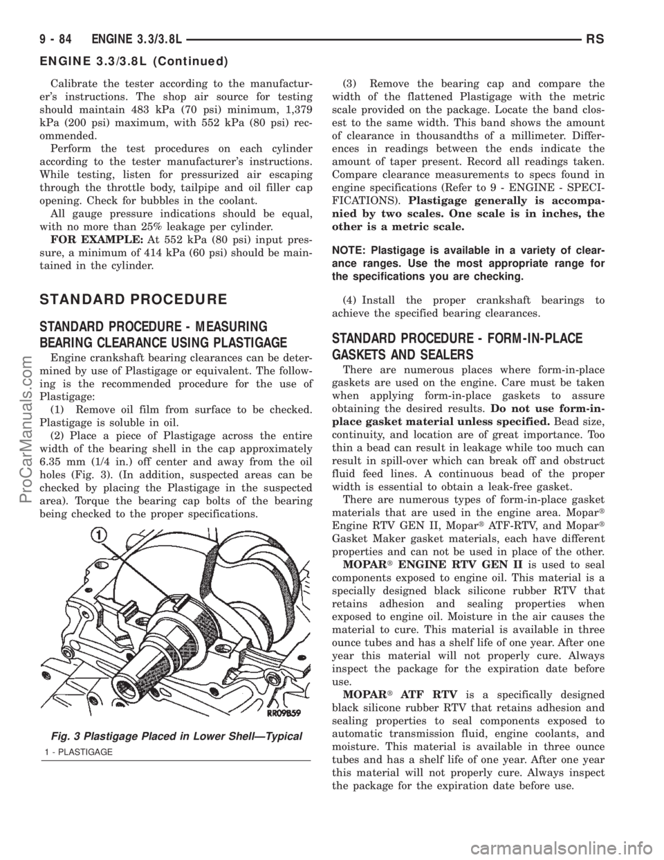
(2) Place a piece of Plastigage across the entire
width of the bearing shell in the cap approximately
6.35 mm (1/4 in.) off center and away from the oil
holes (Fig. 3). (In addition, suspected areas can be
checked by placing the Plastigage in the suspected
area). Torque the bearing cap bolts of the bearing
being checked to the proper specifications.(3) Remove the bearing cap and compare the
width of the flattened Plastigage with the metric
scale provided on the package. Locate the band clos-
est to the same width. This band shows the amount
of clearance in thousandths of a millimeter. Differ-
ences in readings between the ends indicate the
amount of taper present. Record all readings taken.
Compare clearance measurements to specs found in
engine specifications (Refer to 9 - ENGINE - SPECI-
FICATIONS).Plastigage generally is accompa-
nied by two scales. One scale is in inches, the
other is a metric scale.
NOTE: Plastigage is available in a variety of clear-
ance ranges. Use the most appropriate range for
the specifications you are checking.
(4) Install the proper crankshaft bearings to
achieve the specified bearing clearances.
STANDARD PROCEDURE - FORM-IN-PLACE
GASKETS AND SEALERS
There are numerous places where form-in-place
gaskets are used on the engine. Care must be taken
when applying form-in-place gaskets to assure
obtaining the desired results.Do not use form-in-
place gasket material unless specified.Bead size,
continuity, and location are of great importance. Too
thin a bead can result in leakage while too much can
result in spill-over which can break off and obstruct
fluid feed lines. A continuous bead of the proper
width is essential to obtain a leak-free gasket.
There are numerous types of form-in-place gasket
materials that are used in the engine area. Mopart
Engine RTV GEN II, MopartATF-RTV, and Mopart
Gasket Maker gasket materials, each have different
properties and can not be used in place of the other.
MOPARtENGINE RTV GEN IIis used to seal
components exposed to engine oil. This material is a
specially designed black silicone rubber RTV that
retains adhesion and sealing properties when
exposed to engine oil. Moisture in the air causes the
material to cure. This material is available in three
ounce tubes and has a shelf life of one year. After one
year this material will not properly cure. Always
inspect the package for the expiration date before
use.
MOPARtATF RTVis a specifically designed
black silicone rubber RTV that retains adhesion and
sealing properties to seal components exposed to
automatic transmission fluid, engine coolants, and
moisture. This material is available in three ounce
tubes and has a shelf life of one year. After one year
this material will not properly cure. Always inspect
the package for the expiration date before use.
Fig. 3 Plastigage Placed in Lower ShellÐTypical
1 - PLASTIGAGE
9 - 84 ENGINE 3.3/3.8LRS
ENGINE 3.3/3.8L (Continued)
ProCarManuals.com
Page 1316 of 2399
(4) Remove camshaft thrust plate (Fig. 47).
(5) Install a long bolt into front of camshaft to
facilitate removal of the camshaft.
(6) Remove the camshaft (Fig. 47), being careful
not to damage cam bearings with the cam lobes.
NOTE: The camshaft bearings are serviced with the
engine block.
INSPECTION
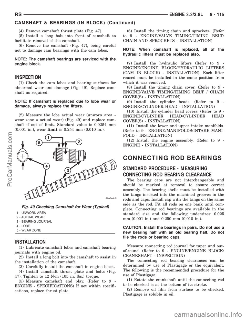
(1) Check the cam lobes and bearing surfaces for
abnormal wear and damage (Fig. 49). Replace cam-
shaft as required.
NOTE: If camshaft is replaced due to lobe wear or
damage, always replace the lifters.
(2) Measure the lobe actual wear (unworn area -
wear zone = actual wear) (Fig. 49) and replace cam-
shaft if out of limit. Standard value is 0.0254 mm
(0.001 in.), wearlimitis 0.254 mm (0.010 in.).
INSTALLATION
(1) Lubricate camshaft lobes and camshaft bearing
journals with engine oil.
(2) Install a long bolt into the camshaft to assist in
the installation of the camshaft.
(3) Carefully install the camshaft in engine block.
(4) Install camshaft thrust plate and bolts (Fig.
47). Tighten to 12 N´m (105 in. lbs.) torque.
(5) Measure camshaft end play. (Refer to 9 -
ENGINE - SPECIFICATIONS) If not within specifi-
cations, replace thrust plate.(6) Install the timing chain and sprockets. (Refer
to 9 - ENGINE/VALVE TIMING/TIMING BELT/
CHAIN AND SPROCKETS - INSTALLATION)
NOTE: When camshaft is replaced, all of the
hydraulic lifters must be replaced also.
(7) Install the hydraulic lifters (Refer to 9 -
ENGINE/ENGINE BLOCK/HYDRAULIC LIFTERS
(CAM IN BLOCK) - INSTALLATION). Each lifter
reused must be installed in the same position from
which it was removed.
(8) Install the timing chain cover. (Refer to 9 -
ENGINE/VALVE TIMING/TIMING BELT / CHAIN
COVER(S) - INSTALLATION)
(9) Install the cylinder heads. (Refer to 9 -
ENGINE/CYLINDER HEAD - INSTALLATION)
(10) Install the cylinder head covers. (Refer to 9 -
ENGINE/CYLINDER HEAD/CYLINDER HEAD
COVER(S) - INSTALLATION)
(11) Install the lower and upper intake manifolds.
(Refer to 9 - ENGINE/MANIFOLDS/INTAKE MANI-
FOLD - INSTALLATION)
(12) Install the engine assembly. (Refer to 9 -
ENGINE - INSTALLATION)
CONNECTING ROD BEARINGS
STANDARD PROCEDURE - MEASURING
CONNECTING ROD BEARING CLEARANCE
The bearing caps are not interchangeable and
should be marked at removal to ensure correct
assembly. The bearing shells must be installed with
the tangs inserted into the machined grooves in the
rods and caps. Install cap with the tangs on the same
side as the rod. Fit all rods on one bank until com-
plete. Connecting rod bearings are available in the
standard size and the following undersizes: 0.025
mm (0.001 in.) and 0.250 mm (0.010 in.).
CAUTION: Install the bearings in pairs. Do not use a
new bearing half with an old bearing half. Do not
file the rods or bearing caps.
Measure connecting rod journal for taper and out-
of-round. (Refer to 9 - ENGINE/ENGINE BLOCK/
CRANKSHAFT - INSPECTION)
The connecting rod bearing clearances can be
determined by use of Plastigage or the equivalent.
The following is the recommended procedure for the
use of Plastigage:
(1) Rotate the crankshaft until the connecting rod
to be checked is at the bottom of its stroke.
(2) Remove oil film from surface to be checked.
Plastigage is soluble in oil.
Fig. 49 Checking Camshaft for Wear (Typical)
1 - UNWORN AREA
2 - ACTUAL WEAR
3 - BEARING JOURNAL
4 - LOBE
5 - WEAR ZONE
RSENGINE 3.3/3.8L9 - 115
CAMSHAFT & BEARINGS (IN BLOCK) (Continued)
ProCarManuals.com
Page 1318 of 2399
DESCRIPTION - 3.8L
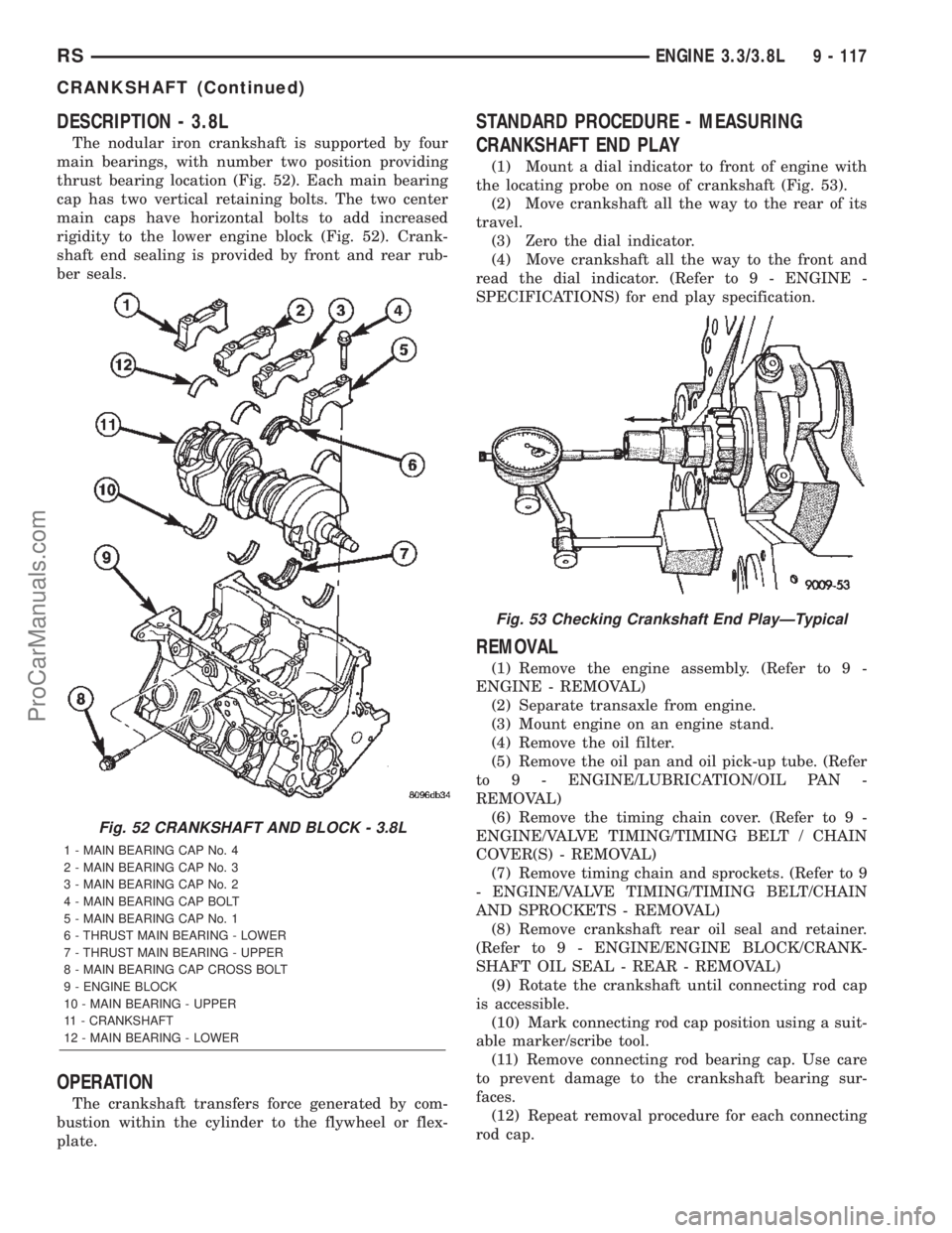
The nodular iron crankshaft is supported by four
main bearings, with number two position providing
thrust bearing location (Fig. 52). Each main bearing
cap has two vertical retaining bolts. The two center
main caps have horizontal bolts to add increased
rigidity to the lower engine block (Fig. 52). Crank-
shaft end sealing is provided by front and rear rub-
ber seals.
OPERATION
The crankshaft transfers force generated by com-
bustion within the cylinder to the flywheel or flex-
plate.
STANDARD PROCEDURE - MEASURING
CRANKSHAFT END PLAY
(1) Mount a dial indicator to front of engine with
the locating probe on nose of crankshaft (Fig. 53).
(2) Move crankshaft all the way to the rear of its
travel.
(3) Zero the dial indicator.
(4) Move crankshaft all the way to the front and
read the dial indicator. (Refer to 9 - ENGINE -
SPECIFICATIONS) for end play specification.
REMOVAL
(1) Remove the engine assembly. (Refer to 9 -
ENGINE - REMOVAL)
(2) Separate transaxle from engine.
(3) Mount engine on an engine stand.
(4) Remove the oil filter.
(5) Remove the oil pan and oil pick-up tube. (Refer
to 9 - ENGINE/LUBRICATION/OIL PAN -
REMOVAL)
(6) Remove the timing chain cover. (Refer to 9 -
ENGINE/VALVE TIMING/TIMING BELT / CHAIN
COVER(S) - REMOVAL)
(7) Remove timing chain and sprockets. (Refer to 9
- ENGINE/VALVE TIMING/TIMING BELT/CHAIN
AND SPROCKETS - REMOVAL)
(8) Remove crankshaft rear oil seal and retainer.
(Refer to 9 - ENGINE/ENGINE BLOCK/CRANK-
SHAFT OIL SEAL - REAR - REMOVAL)
(9) Rotate the crankshaft until connecting rod cap
is accessible.
(10) Mark connecting rod cap position using a suit-
able marker/scribe tool.
(11) Remove connecting rod bearing cap. Use care
to prevent damage to the crankshaft bearing sur-
faces.
(12) Repeat removal procedure for each connecting
rod cap.
Fig. 52 CRANKSHAFT AND BLOCK - 3.8L
1 - MAIN BEARING CAP No. 4
2 - MAIN BEARING CAP No. 3
3 - MAIN BEARING CAP No. 2
4 - MAIN BEARING CAP BOLT
5 - MAIN BEARING CAP No. 1
6 - THRUST MAIN BEARING - LOWER
7 - THRUST MAIN BEARING - UPPER
8 - MAIN BEARING CAP CROSS BOLT
9 - ENGINE BLOCK
10 - MAIN BEARING - UPPER
11 - CRANKSHAFT
12 - MAIN BEARING - LOWER
Fig. 53 Checking Crankshaft End PlayÐTypical
RSENGINE 3.3/3.8L9 - 117
CRANKSHAFT (Continued)
ProCarManuals.com
Page 1321 of 2399
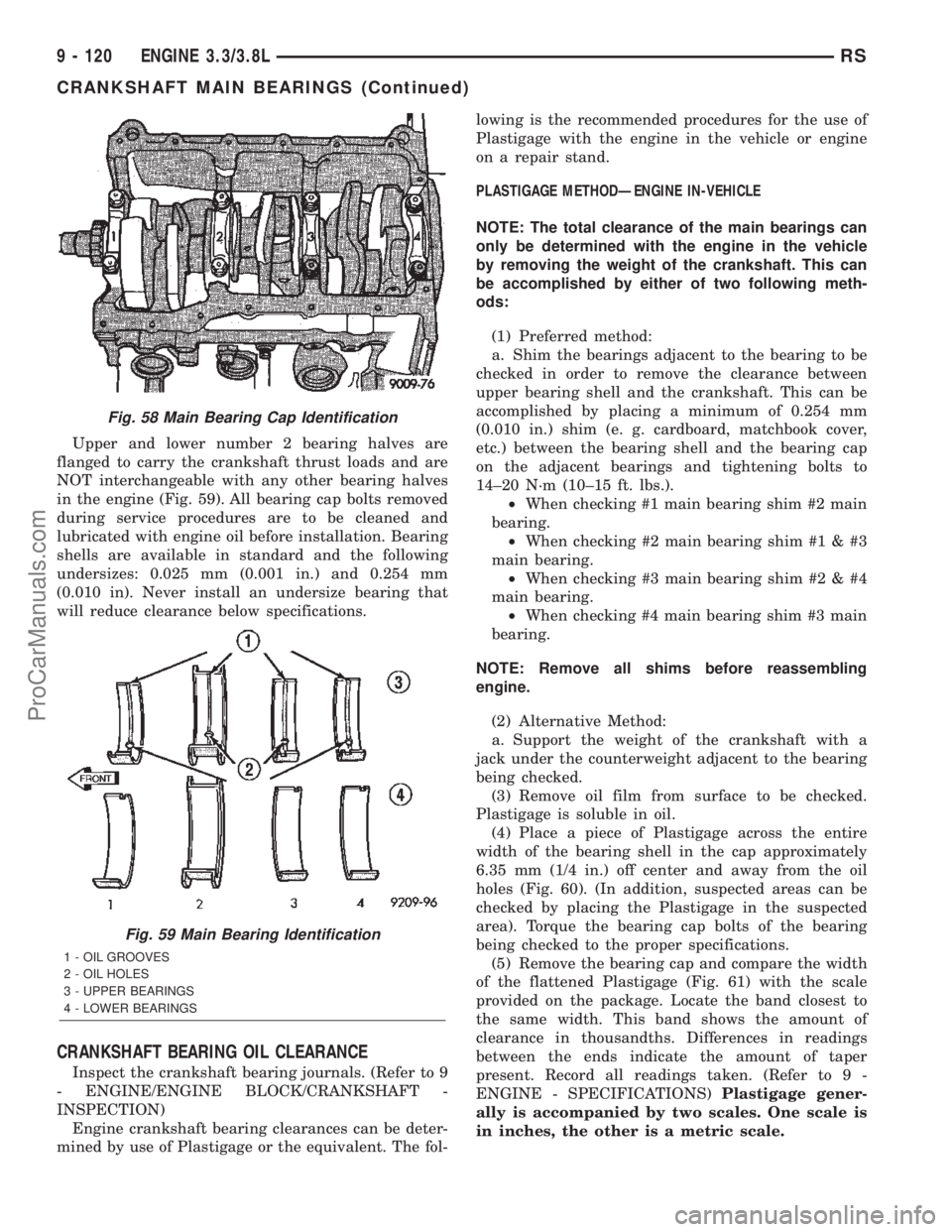
Upper and lower number 2 bearing halves are
flanged to carry the crankshaft thrust loads and are
NOT interchangeable with any other bearing halves
in the engine (Fig. 59). All bearing cap bolts removed
during service procedures are to be cleaned and
lubricated with engine oil before installation. Bearing
shells are available in standard and the following
undersizes: 0.025 mm (0.001 in.) and 0.254 mm
(0.010 in). Never install an undersize bearing that
will reduce clearance below specifications.
CRANKSHAFT BEARING OIL CLEARANCE
Inspect the crankshaft bearing journals. (Refer to 9
- ENGINE/ENGINE BLOCK/CRANKSHAFT -
INSPECTION)
Engine crankshaft bearing clearances can be deter-
mined by use of Plastigage or the equivalent. The fol-lowing is the recommended procedures for the use of
Plastigage with the engine in the vehicle or engine
on a repair stand.
PLASTIGAGE METHODÐENGINE IN-VEHICLE
NOTE: The total clearance of the main bearings can
only be determined with the engine in the vehicle
by removing the weight of the crankshaft. This can
be accomplished by either of two following meth-
ods:
(1) Preferred method:
a. Shim the bearings adjacent to the bearing to be
checked in order to remove the clearance between
upper bearing shell and the crankshaft. This can be
accomplished by placing a minimum of 0.254 mm
(0.010 in.) shim (e. g. cardboard, matchbook cover,
etc.) between the bearing shell and the bearing cap
on the adjacent bearings and tightening bolts to
14±20 N´m (10±15 ft. lbs.).
²When checking #1 main bearing shim #2 main
bearing.
²When checking #2 main bearing shim #1 & #3
main bearing.
²When checking #3 main bearing shim #2 & #4
main bearing.
²When checking #4 main bearing shim #3 main
bearing.
NOTE: Remove all shims before reassembling
engine.
(2) Alternative Method:
a. Support the weight of the crankshaft with a
jack under the counterweight adjacent to the bearing
being checked.
(3) Remove oil film from surface to be checked.
Plastigage is soluble in oil.
(4) Place a piece of Plastigage across the entire
width of the bearing shell in the cap approximately
6.35 mm (1/4 in.) off center and away from the oil
holes (Fig. 60). (In addition, suspected areas can be
checked by placing the Plastigage in the suspected
area). Torque the bearing cap bolts of the bearing
being checked to the proper specifications.
(5) Remove the bearing cap and compare the width
of the flattened Plastigage (Fig. 61) with the scale
provided on the package. Locate the band closest to
the same width. This band shows the amount of
clearance in thousandths. Differences in readings
between the ends indicate the amount of taper
present. Record all readings taken. (Refer to 9 -
ENGINE - SPECIFICATIONS)Plastigage gener-
ally is accompanied by two scales. One scale is
in inches, the other is a metric scale.
Fig. 58 Main Bearing Cap Identification
Fig. 59 Main Bearing Identification
1 - OIL GROOVES
2 - OIL HOLES
3 - UPPER BEARINGS
4 - LOWER BEARINGS
9 - 120 ENGINE 3.3/3.8LRS
CRANKSHAFT MAIN BEARINGS (Continued)
ProCarManuals.com
Page 1322 of 2399
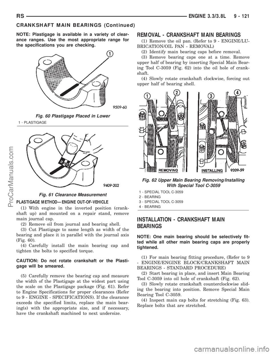
NOTE: Plastigage is available in a variety of clear-
ance ranges. Use the most appropriate range for
the specifications you are checking.
PLASTIGAGE METHODÐENGINE OUT-OF-VEHICLE
(1) With engine in the inverted position (crank-
shaft up) and mounted on a repair stand, remove
main journal cap.
(2) Remove oil from journal and bearing shell.
(3) Cut Plastigage to same length as width of the
bearing and place it in parallel with the journal axis
(Fig. 60).
(4) Carefully install the main bearing cap and
tighten the bolts to specified torque.
CAUTION: Do not rotate crankshaft or the Plasti-
gage will be smeared.
(5) Carefully remove the bearing cap and measure
the width of the Plastigage at the widest part using
the scale on the Plastigage package (Fig. 61). Refer
to Engine Specifications for proper clearances (Refer
to 9 - ENGINE - SPECIFICATIONS). If the clearance
exceeds the specified limits, replace the main bear-
ing(s) with the appropriate size, and if necessary,
have the crankshaft machined to next undersize.REMOVAL - CRANKSHAFT MAIN BEARINGS
(1) Remove the oil pan. (Refer to 9 - ENGINE/LU-
BRICATION/OIL PAN - REMOVAL)
(2) Identify main bearing caps before removal.
(3) Remove bearing caps one at a time. Remove
upper half of bearing by inserting Special Main Bear-
ing Tool C-3059 (Fig. 62) into the oil hole of crank-
shaft.
(4) Slowly rotate crankshaft clockwise, forcing out
upper half of bearing shell.
INSTALLATION - CRANKSHAFT MAIN
BEARINGS
NOTE: One main bearing should be selectively fit-
ted while all other main bearing caps are properly
tightened.
(1) For main bearing fitting procedure, (Refer to 9
- ENGINE/ENGINE BLOCK/CRANKSHAFT MAIN
BEARINGS - STANDARD PROCEDURE)
(2) Start bearing in place, and insert Main Bearing
Tool C-3059 into oil hole of crankshaft (Fig. 62).
(3) Slowly rotate crankshaft counterclockwise slid-
ing the bearing into position. Remove Special Main
Bearing Tool C-3059.
(4) Inspect main cap bolts for stretching (Fig. 63).
Replace bolts that are stretched.
Fig. 60 Plastigage Placed in Lower
1 - PLASTIGAGE
Fig. 61 Clearance Measurement
Fig. 62 Upper Main Bearing Removing/Installing
With Special Tool C-3059
1 - SPECIAL TOOL C-3059
2 - BEARING
3 - SPECIAL TOOL C-3059
4 - BEARING
RSENGINE 3.3/3.8L9 - 121
CRANKSHAFT MAIN BEARINGS (Continued)
ProCarManuals.com
Page 1328 of 2399
STANDARD PROCEDURE
STANDARD PROCEDURE - FITTING
CONNECTING RODS
The bearing caps are not interchangeable or
reversible, and should be marked at removal to
ensure correct reassembly. The bearing shells must
be installed with the tangs inserted into the
machined grooves in the rods and caps. Install cap
with the tangs on the same side as the rod. For con-
necting rod bearing fitting (Refer to 9 - ENGINE/EN-
GINE BLOCK/CONNECTING ROD BEARINGS -
STANDARD PROCEDURE). Fit all connecting rods
on one bank until complete.
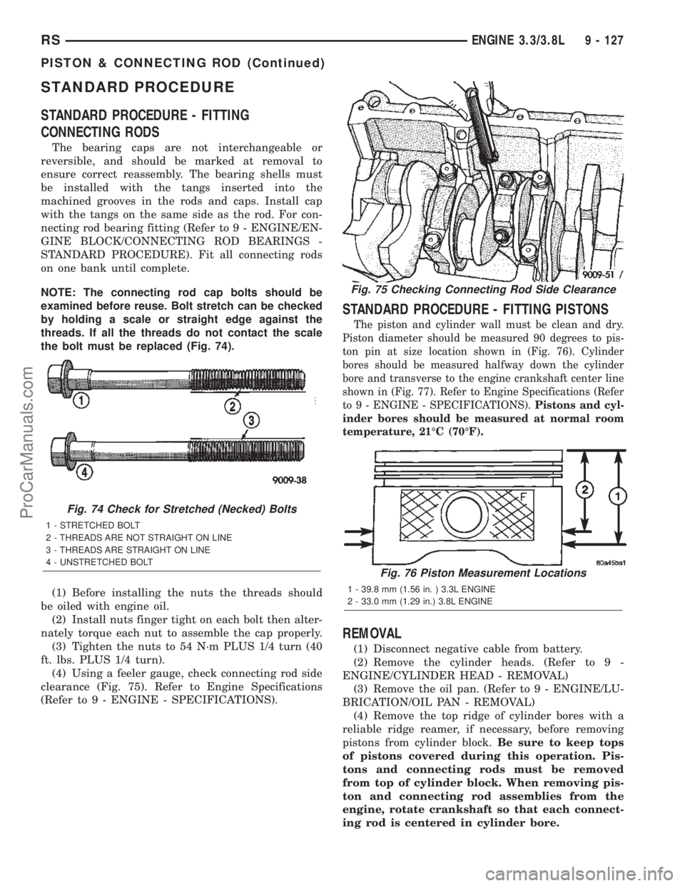
NOTE: The connecting rod cap bolts should be
examined before reuse. Bolt stretch can be checked
by holding a scale or straight edge against the
threads. If all the threads do not contact the scale
the bolt must be replaced (Fig. 74).
(1) Before installing the nuts the threads should
be oiled with engine oil.
(2) Install nuts finger tight on each bolt then alter-
nately torque each nut to assemble the cap properly.
(3) Tighten the nuts to 54 N´m PLUS 1/4 turn (40
ft. lbs. PLUS 1/4 turn).
(4) Using a feeler gauge, check connecting rod side
clearance (Fig. 75). Refer to Engine Specifications
(Refer to 9 - ENGINE - SPECIFICATIONS).
STANDARD PROCEDURE - FITTING PISTONS
The piston and cylinder wall must be clean and dry.
Piston diameter should be measured 90 degrees to pis-
ton pin at size location shown in (Fig. 76). Cylinder
bores should be measured halfway down the cylinder
bore and transverse to the engine crankshaft center line
shown in (Fig. 77). Refer to Engine Specifications (Refer
to 9 - ENGINE - SPECIFICATIONS).Pistons and cyl-
inder bores should be measured at normal room
temperature, 21ÉC (70ÉF).
REMOVAL
(1) Disconnect negative cable from battery.
(2) Remove the cylinder heads. (Refer to 9 -
ENGINE/CYLINDER HEAD - REMOVAL)
(3) Remove the oil pan. (Refer to 9 - ENGINE/LU-
BRICATION/OIL PAN - REMOVAL)
(4) Remove the top ridge of cylinder bores with a
reliable ridge reamer, if necessary, before removing
pistons from cylinder block.Be sure to keep tops
of pistons covered during this operation. Pis-
tons and connecting rods must be removed
from top of cylinder block. When removing pis-
ton and connecting rod assemblies from the
engine, rotate crankshaft so that each connect-
ing rod is centered in cylinder bore.
Fig. 74 Check for Stretched (Necked) Bolts
1 - STRETCHED BOLT
2 - THREADS ARE NOT STRAIGHT ON LINE
3 - THREADS ARE STRAIGHT ON LINE
4 - UNSTRETCHED BOLT
Fig. 75 Checking Connecting Rod Side Clearance
Fig. 76 Piston Measurement Locations
1 - 39.8 mm (1.56 in. ) 3.3L ENGINE
2 - 33.0 mm (1.29 in.) 3.8L ENGINE
RSENGINE 3.3/3.8L9 - 127
PISTON & CONNECTING ROD (Continued)
ProCarManuals.com
Page 1329 of 2399
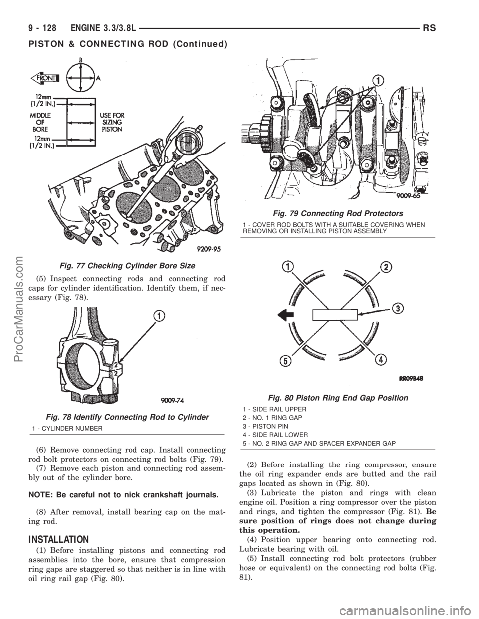
(5) Inspect connecting rods and connecting rod
caps for cylinder identification. Identify them, if nec-
essary (Fig. 78).
(6) Remove connecting rod cap. Install connecting
rod bolt protectors on connecting rod bolts (Fig. 79).
(7) Remove each piston and connecting rod assem-
bly out of the cylinder bore.
NOTE: Be careful not to nick crankshaft journals.
(8) After removal, install bearing cap on the mat-
ing rod.
INSTALLATION
(1) Before installing pistons and connecting rod
assemblies into the bore, ensure that compression
ring gaps are staggered so that neither is in line with
oil ring rail gap (Fig. 80).(2) Before installing the ring compressor, ensure
the oil ring expander ends are butted and the rail
gaps located as shown in (Fig. 80).
(3) Lubricate the piston and rings with clean
engine oil. Position a ring compressor over the piston
and rings, and tighten the compressor (Fig. 81).Be
sure position of rings does not change during
this operation.
(4) Position upper bearing onto connecting rod.
Lubricate bearing with oil.
(5) Install connecting rod bolt protectors (rubber
hose or equivalent) on the connecting rod bolts (Fig.
81).
Fig. 77 Checking Cylinder Bore Size
Fig. 78 Identify Connecting Rod to Cylinder
1 - CYLINDER NUMBER
Fig. 79 Connecting Rod Protectors
1 - COVER ROD BOLTS WITH A SUITABLE COVERING WHEN
REMOVING OR INSTALLING PISTON ASSEMBLY
Fig. 80 Piston Ring End Gap Position
1 - SIDE RAIL UPPER
2 - NO. 1 RING GAP
3 - PISTON PIN
4 - SIDE RAIL LOWER
5 - NO. 2 RING GAP AND SPACER EXPANDER GAP
9 - 128 ENGINE 3.3/3.8LRS
PISTON & CONNECTING ROD (Continued)
ProCarManuals.com