2002 CHRYSLER CARAVAN check engine
[x] Cancel search: check enginePage 1506 of 2399
(6) Start engine and let idle just long enough to
circulate power steering fluid through the analyzer
and hoses. Shut off engine.
(7) Check power steering fluid level and add fluid
as necessary. Start engine again and let idle until the
air is out of the fluid.
(8) Gauge should read below 300 psi (2068 kPa). If
above, inspect the hoses for restrictions and repair as
necessary. The initial pressure should be in the range
of 100-275 psi (689-1896 kPa) depending on fluid
temperature. The flow meter should read above 1.5
GPM.
CAUTION: The following test procedure involves
testing maximum pump pressure output and flow
control valve operation. Do not leave valve closed
for more than four seconds as the pump could be
damaged.
NOTE: Power steering pump maximum pressure for
2.4L engines is 1,200 ± 1,350 psi (8,274 ± 9,308
kPa). Power steering pump maximum pressure for
all other engines is 1,400 ± 1,500 psi (9,653 ± 10,342
kPa).
(9) Close analyzer valve fully three times and
record highest pressure indicated each time. All three
readings must be within specifications. If any of the
three power steering pump pressures are above orbelow specifications, replace pump. (Refer to 19 -
STEERING/PUMP - REMOVAL)
CAUTION: Do not force the steering to operate
against the stops for more than 4 seconds at a time
because pump damage can result.
(10) Once the pump has been verified as working
correctly, completely open the valve on the Power
Steering Analyzer. Turn the steering wheel to the
extreme left until the stop in the steering gear is
met. Hold it there for 2±4 seconds, then release it.
Now turn the steering wheel to the right until the
right stop is met. Hold it there for 2±4 seconds, then
release it. Record the stabilized pressure at each
position. Compare the recorded readings to the spec-
ifications. If the output pressures are not within 100
psi (689 kPa) of one another against either stop or
are below specifications, the steering gear is leaking
internally and must be replaced. (Refer to 19 -
STEERING/GEAR - REMOVAL)
DIAGNOSIS AND TESTING - STEERING
SYSTEM DIAGNOSIS CHARTS
NOTE: There are three diagnosis charts following
that cover POWER STEERING NOISE, STEERING
WHEEL FEEL, and POWER STEERING FLUID.
POWER STEERING NOISE
CONDITION POSSIBLE CAUSES CORRECTION
OBJECTIONABLE HISS
OR WHISTLE*1. Damaged or mispositioned
steering column shaft/coupling dash
panel seal.1. Reposition or replace steering
column shaft/coupling dash panel seal.
2. Noisy valve in power steering
gear.2. Replace power steering gear.
3. Mis-routed power steering hose. 3. Check routing of power steering
hoses. Ensure hoses do not come in
unwanted contact with other
components and objects.
RATTLE OR EXCESSIVE
CLUNK**1. Power steering gear loose on front
suspension crossmember.1. Inspect power steering gear
mounting bolts. Replace as necessary.
Tighten to the specified torque.
2. Front suspension crossmember
mounting fasteners loose at frame.2. Tighten the front suspension
crossmember mounting fasteners to the
specified torque.
3. Loose tie rod (outer or inner). 3. Check tie rod pivot points for wear.
Replace worn/loose parts as required.
RSSTEERING19-3
STEERING (Continued)
ProCarManuals.com
Page 1509 of 2399
CONDITION POSSIBLE CAUSES CORRECTION
2. Steering column lower bearing
spring retainer slipped on steering
column shaft.2. Replace steering column.
3. Loose steering column to
instrument panel fasteners.3. Tighten fasteners to specified torque.
STEERING WHEEL, DASH
OR VEHICLE VIBRATES
DURING LOW SPEED OR
STANDSTILL STEERING
MANEUVERS.1. Air in the fluid of the power
steering system.1. Bleed air from system following the
power steering pump initial operation
service procedure.*
2. Tires not properly inflated. 2. Inflate tires to the specified pressure.
3. Excessive engine vibration. 3. Ensure that the engine is tuned properly.
4. Loose tie rod end jam nut. 4. Tighten the inner to outer tie rod jam nut
to the specified torque.
5.Overcharged air conditioning
system.5.Check air conditioning pump head
pressure and correct as necessary.
6. Grounded engine mount. 6. Repair as necessary.
7. Loose outer tie rod. 7. Replace outer tie rod.
STEERING CATCHES,
SURGES OR STICKS IN
CERTAIN POSITIONS OR
IS DIFFICULT TO TURN.
***1. Low power steering fluid level. 1. Fill power steering fluid reservoir to
specified level and check for leaks.
2. Tires not inflated to specified
pressure.2. Inflate tires to the specified pressure.
3. Lack of lubrication in front lower
control arm ball joints.3. Lubricate ball joints if ball joints are not a
lubricated-for-life type ball joint. If ball joint
is a lubricated-for-life ball joint, replace ball
joint.
4. Worn or binding lower control arm
ball joint.4. Replace lower control arm ball joint.
5. Lack of lubrication in steering gear
outer tie rod ends.5. Lubricate tie rod ends if they are not a
lubricated-for-life type. If tie rod end is a
lubricated-for-life type, replace tie rod end.
6. Loose power steering pump drive
belt.6. Tighten the power steering pump drive
belt to specifications or replace automatic
tensioner where applicable. If drive belt is
worn or glazed, replace belt.
7. Faulty power steering pump
(Perform Power Steering Flow and
Pressure Test).7. Replace power steering pump.
8. Faulty power steering gear
(Perform Power Steering Flow and
Pressure Test).8. Replace power steering gear.
9. Excessive friction in steering
column or intermediate shaft/coupler.9. Isolate and correct condition.
10. Excessive friction in power
steering gear.10. Replace power steering gear.
19 - 6 STEERINGRS
STEERING (Continued)
ProCarManuals.com
Page 1529 of 2399
GEAR
TABLE OF CONTENTS
page page
GEAR
DESCRIPTION.........................26
OPERATION...........................26
WARNING
WARNINGS AND CAUTIONS.............26
REMOVAL
REMOVAL - LHD GEAR.................26
REMOVAL - RHD GEAR................29INSTALLATION
INSTALLATION - LHD GEAR.............32
INSTALLATION - RHD GEAR.............33
SPECIAL TOOLS
POWER STEERING GEAR..............34
OUTER TIE ROD
REMOVAL.............................34
INSTALLATION.........................34
GEAR
DESCRIPTION
This vehicle is equipped with a rack and pinion
power steering gear (Fig. 1). It is mounted to the
underside of the front suspension cradle/crossmem-
ber.
The steering column is attached to the gear
through the use of an intermediate shaft and cou-
plers. The outer ends of the power steering gear's
outer tie rods connect to the steering knuckles.
NOTE: The power steering gear should NOT be ser-
viced or adjusted unless DaimlerChrysler Corpora-
tion authorizes. If a malfunction or oil leak occurs,
the complete steering gear should be replaced.
Only the outer tie rods may be replaced separately
from the rest of the gear.
OPERATION
Turning of the steering wheel is converted into lin-
ear (side-to-side) travel through the meshing of the
helical pinion teeth with the rack teeth in the steer-
ing gear. This travel pushes and pulls the tie rods to
change the direction of the vehicle's front wheels.
Power assist steering provided by the power steer-
ing pump is controlled by an open center, rotary type
control valve which directs oil from the pump to
either side of the integral rack piston upon demand.
Road feel is controlled by the diameter of a torsion
bar which initially steers the vehicle. As required
steering effort increases, as in a turn, the torsion bar
twists, causing relative rotary motion between the
rotary valve body and the valve spool. This move-
ment directs oil behind the integral rack piston
which, in turn, builds hydraulic pressure and assists
in the turning effort.Manual steering control of the vehicle can be main-
tained if power steering assist is lost. However,
under this condition, steering effort is significantly
increased.
WARNING
WARNINGS AND CAUTIONS
WARNING: POWER STEERING FLUID, ENGINE
PARTS AND EXHAUST SYSTEM MAY BE
EXTREMELY HOT IF ENGINE HAS BEEN RUNNING.
DO NOT START ENGINE WITH ANY LOOSE OR DIS-
CONNECTED HOSES. DO NOT ALLOW HOSES TO
TOUCH HOT EXHAUST MANIFOLD OR CATALYST.
WARNING: FLUID LEVEL SHOULD BE CHECKED
WITH THE ENGINE OFF TO PREVENT PERSONAL
INJURY FROM MOVING PARTS.
CAUTION: When the system is open, cap all open
ends of the hoses, power steering pump fittings or
power steering gear ports to prevent entry of for-
eign material into the components.
REMOVAL
REMOVAL - LHD GEAR
(1) Remove cap from power steering fluid reser-
voir.
(2) Using a siphon pump, remove as much fluid as
possible from the power steering fluid reservoir.Use
care not to damage the filter mesh below the
fluid surface.
19 - 26 GEARRS
ProCarManuals.com
Page 1539 of 2399
PUMP
TABLE OF CONTENTS
page page
PUMP
DESCRIPTION
DESCRIPTION - PUMP (2.4L/3.3L/3.8L
ENGINE)............................36
DESCRIPTION - PUMP (2.5L DIESEL)......37
OPERATION...........................37
WARNING.............................37
CAUTION.............................37
STANDARD PROCEDURE - POWER
STEERING PUMP INITIAL OPERATION.....37
REMOVAL
REMOVAL - PUMP (2.4L ENGINE).........38
REMOVAL - PUMP (3.3L/3.8L ENGINE).....40
REMOVAL - PUMP (2.5L DIESEL).........41
DISASSEMBLY - PUMP (PULLEY)..........41
ASSEMBLY - PUMP (PULLEY).............42
INSTALLATION
INSTALLATION - PUMP (2.4L ENGINE).....43
INSTALLATION - PUMP (3.3L/3.8L ENGINE) . 43
INSTALLATION - PUMP (2.5L DIESEL)......43
SPECIAL TOOLS
POWER STEERING PUMP..............44
FLUID
STANDARD PROCEDURE - POWER
STEERING FLUID LEVEL CHECKING......44
FLUID COOLER
DESCRIPTION.........................45
OPERATION...........................45
REMOVAL.............................45
INSTALLATION.........................45
HOSE - POWER STEERING PRESSURE
REMOVAL
REMOVAL - 2.4L ENGINE...............45REMOVAL - 3.3L/3.8L ENGINE...........46
INSTALLATION
INSTALLATION - 2.4L ENGINE...........46
INSTALLATION - 3.3L/3.8L ENGINE........47
HOSE - POWER STEERING RETURN
REMOVAL
REMOVAL - 2.4L ENGINE...............49
REMOVAL - 3.3L/3.8L ENGINE...........49
INSTALLATION
INSTALLATION - 2.4L ENGINE...........50
INSTALLATION - 3.3L/3.8L ENGINE........50
HOSE - POWER STEERING SUPPLY
REMOVAL
REMOVAL - 2.4L ENGINE...............51
REMOVAL - 3.3L/3.8L ENGINE...........51
INSTALLATION
INSTALLATION - 2.4L ENGINE...........51
INSTALLATION - 3.3L/3.8L ENGINE........51
RESERVOIR - POWER STEERING FLUID
DESCRIPTION
DESCRIPTION - 2.4L/3.3L/3.8L ENGINE....51
DESCRIPTION - 2.5L DIESEL............52
OPERATION...........................52
REMOVAL
REMOVAL - 2.4L ENGINE...............52
REMOVAL - 3.3L/3.8L ENGINE...........52
REMOVAL - 2.5L DIESEL................52
INSTALLATION
INSTALLATION - 2.4L ENGINE...........53
INSTALLATION - 3.3L/3.8L ENGINE........53
INSTALLATION - 2.5L DIESEL............53
PUMP
DESCRIPTION
DESCRIPTION - PUMP (2.4L/3.3L/3.8L
ENGINE)
Hydraulic pressure for the operation of the power
steering gear is provided by a belt driven power
steering pump. The power steering pump is mounted
on the back side of the engine on all engine applica-
tions. The pumps are different depending on the
engine option. The pump for the 2.4L engine is madeout of cast iron and steel (Fig. 1). The pump used on
the 3.3L/3.8L engine is made of aluminum (Fig. 2).
The pump for the 3.3L/3.8L engine does not have a
return fitting as the pump for the 2.4L engine does.
The power steering return hose on the 3.3L/3.8L
engine goes to the reservoir instead of the pump.
19 - 36 PUMPRS
ProCarManuals.com
Page 1540 of 2399
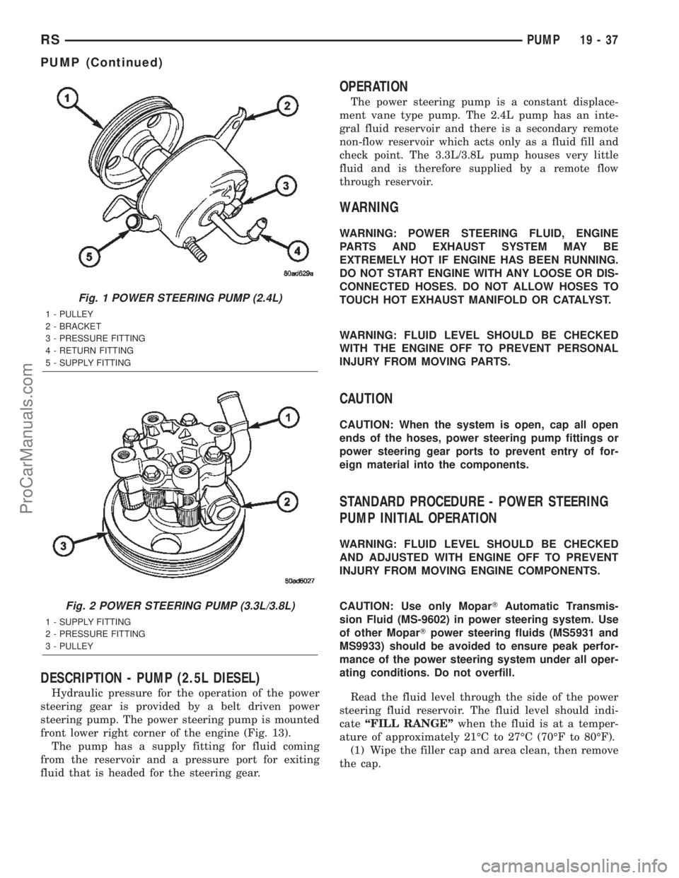
DESCRIPTION - PUMP (2.5L DIESEL)
Hydraulic pressure for the operation of the power
steering gear is provided by a belt driven power
steering pump. The power steering pump is mounted
front lower right corner of the engine (Fig. 13).
The pump has a supply fitting for fluid coming
from the reservoir and a pressure port for exiting
fluid that is headed for the steering gear.
OPERATION
The power steering pump is a constant displace-
ment vane type pump. The 2.4L pump has an inte-
gral fluid reservoir and there is a secondary remote
non-flow reservoir which acts only as a fluid fill and
check point. The 3.3L/3.8L pump houses very little
fluid and is therefore supplied by a remote flow
through reservoir.
WARNING
WARNING: POWER STEERING FLUID, ENGINE
PARTS AND EXHAUST SYSTEM MAY BE
EXTREMELY HOT IF ENGINE HAS BEEN RUNNING.
DO NOT START ENGINE WITH ANY LOOSE OR DIS-
CONNECTED HOSES. DO NOT ALLOW HOSES TO
TOUCH HOT EXHAUST MANIFOLD OR CATALYST.
WARNING: FLUID LEVEL SHOULD BE CHECKED
WITH THE ENGINE OFF TO PREVENT PERSONAL
INJURY FROM MOVING PARTS.
CAUTION
CAUTION: When the system is open, cap all open
ends of the hoses, power steering pump fittings or
power steering gear ports to prevent entry of for-
eign material into the components.
STANDARD PROCEDURE - POWER STEERING
PUMP INITIAL OPERATION
WARNING: FLUID LEVEL SHOULD BE CHECKED
AND ADJUSTED WITH ENGINE OFF TO PREVENT
INJURY FROM MOVING ENGINE COMPONENTS.
CAUTION: Use only MoparTAutomatic Transmis-
sion Fluid (MS-9602) in power steering system. Use
of other MoparTpower steering fluids (MS5931 and
MS9933) should be avoided to ensure peak perfor-
mance of the power steering system under all oper-
ating conditions. Do not overfill.
Read the fluid level through the side of the power
steering fluid reservoir. The fluid level should indi-
cateªFILL RANGEºwhen the fluid is at a temper-
ature of approximately 21ÉC to 27ÉC (70ÉF to 80ÉF).
(1) Wipe the filler cap and area clean, then remove
the cap.
Fig. 1 POWER STEERING PUMP (2.4L)
1 - PULLEY
2 - BRACKET
3 - PRESSURE FITTING
4 - RETURN FITTING
5 - SUPPLY FITTING
Fig. 2 POWER STEERING PUMP (3.3L/3.8L)
1 - SUPPLY FITTING
2 - PRESSURE FITTING
3 - PULLEY
RSPUMP19-37
PUMP (Continued)
ProCarManuals.com
Page 1541 of 2399
(2) Fill the fluid reservoir to the proper level and
let the fluid settle for at least two (2) minutes.
(3) Start the engine and let run for a few seconds,
then turn the engine off.
(4) Add fluid if necessary. Repeat the above steps
until the fluid level remains constant after running
the engine.
(5) Raise the front wheels off the ground.
(6) Start the engine.
(7) Slowly turn the steering wheel right and left,
lightly contacting the wheel stops.
(8) Add fluid if necessary.
(9) Lower the vehicle, then turn the steering wheel
slowly from lock-to-lock.
(10) Stop the engine. Check the fluid level and
refill as required.
(11) If the fluid is extremely foamy, allow the vehi-
cle to stabilize a few minutes, then repeat the above
procedure.
REMOVAL
REMOVAL - PUMP (2.4L ENGINE)
(1) Remove the (-) negative battery cable from the
battery and isolate cable.
(2) Remove the cap from the power steering fluid
reservoir.
(3) Using a siphon pump, remove as much power
steering fluid as possible from the power steering
fluid reservoir.
(4) Raise the vehicle on jack stands or centered on
a frame contact type hoist. See Hoisting in Lubrica-
tion and Maintenance.
(5) Disconnect the oxygen sensor wiring harness
from the vehicle wiring harness at the rear engine
mount bracket.
NOTE: The exhaust system needs to be removed
from the engine to allow for an area to remove the
power steering pump from the vehicle.
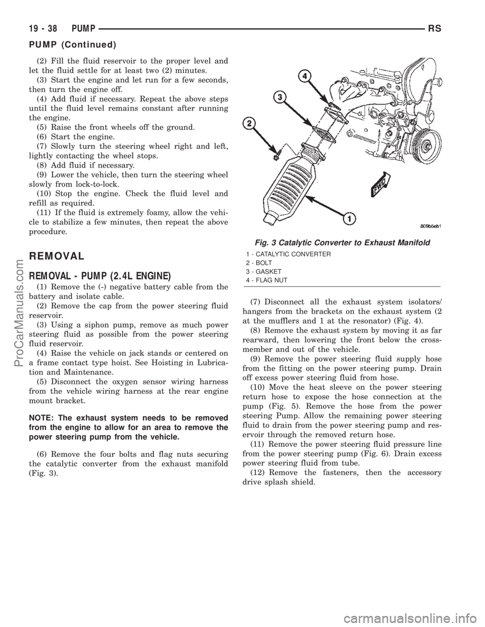
(6) Remove the four bolts and flag nuts securing
the catalytic converter from the exhaust manifold
(Fig. 3).(7) Disconnect all the exhaust system isolators/
hangers from the brackets on the exhaust system (2
at the mufflers and 1 at the resonator) (Fig. 4).
(8) Remove the exhaust system by moving it as far
rearward, then lowering the front below the cross-
member and out of the vehicle.
(9) Remove the power steering fluid supply hose
from the fitting on the power steering pump. Drain
off excess power steering fluid from hose.
(10) Move the heat sleeve on the power steering
return hose to expose the hose connection at the
pump (Fig. 5). Remove the hose from the power
steering Pump. Allow the remaining power steering
fluid to drain from the power steering pump and res-
ervoir through the removed return hose.
(11) Remove the power steering fluid pressure line
from the power steering pump (Fig. 6). Drain excess
power steering fluid from tube.
(12) Remove the fasteners, then the accessory
drive splash shield.
Fig. 3 Catalytic Converter to Exhaust Manifold
1 - CATALYTIC CONVERTER
2 - BOLT
3 - GASKET
4 - FLAG NUT
19 - 38 PUMPRS
PUMP (Continued)
ProCarManuals.com
Page 1547 of 2399
NOTE: Before installing power steering pressure
hose on power steering pump, inspect the O-ring
on the power steering pressure hose for damage
and replace if required.
(4) Install the power steering fluid pressure hose
fitting into the pressure port of the power steering
pump (Fig. 12). Tighten the pressure line to pump
fitting tube nut to a torque of 31 N´m (275 in. lbs.).
(5) Install the power steering fluid supply hose on
the power steering pump supply fitting (Fig. 12).Be
sure hose clamp is properly reinstalled.
(6) Install the accessary drive belt (Refer to 7 -
COOLING/ACCESSORY DRIVE/DRIVE BELTS -
INSTALLATION).
(7) Install the splash shields below the engine
compartment.
(8) Lower the vehicle.
(9) Connect the negative (-) battery cable on the
negative battery post.
(10) Fill and bleed the power steering system
using the Power Steering Pump Initial Operation
Procedure (Refer to 19 - STEERING/PUMP - STAN-
DARD PROCEDURE).
(11) Inspect for leaks.
SPECIAL TOOLS
POWER STEERING PUMP
FLUID
STANDARD PROCEDURE - POWER STEERING
FLUID LEVEL CHECKING
WARNING: FLUID LEVEL SHOULD BE CHECKED
WITH THE ENGINE OFF TO PREVENT INJURY
FROM MOVING PARTS AND TO ENSURE ACCU-
RATE FLUID LEVEL READING.
The fluid level can be read on the exterior of the
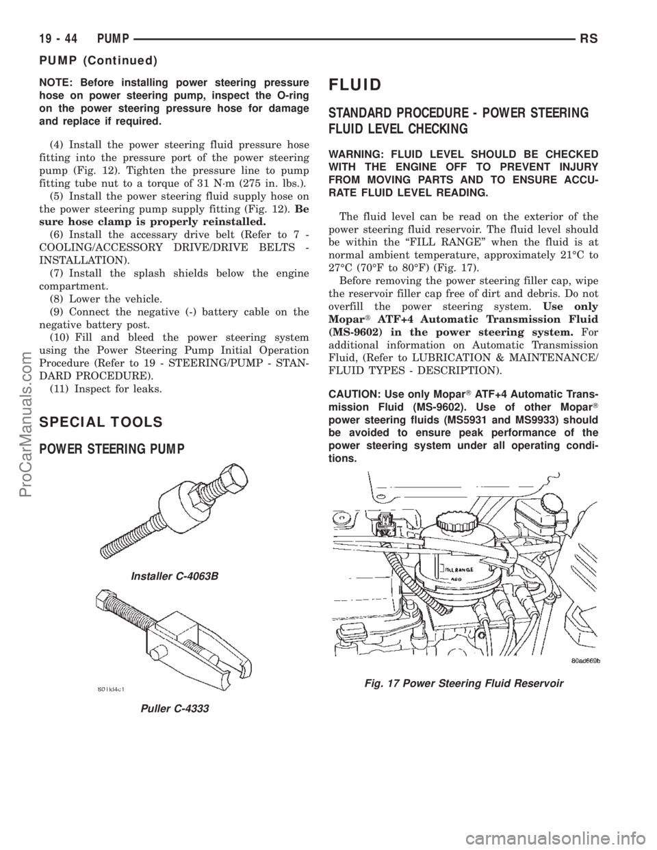
power steering fluid reservoir. The fluid level should
be within the ªFILL RANGEº when the fluid is at
normal ambient temperature, approximately 21ÉC to
27ÉC (70ÉF to 80ÉF) (Fig. 17).
Before removing the power steering filler cap, wipe
the reservoir filler cap free of dirt and debris. Do not
overfill the power steering system.Use only
MopartATF+4 Automatic Transmission Fluid
(MS-9602) in the power steering system.For
additional information on Automatic Transmission
Fluid, (Refer to LUBRICATION & MAINTENANCE/
FLUID TYPES - DESCRIPTION).
CAUTION: Use only MoparTATF+4 Automatic Trans-
mission Fluid (MS-9602). Use of other MoparT
power steering fluids (MS5931 and MS9933) should
be avoided to ensure peak performance of the
power steering system under all operating condi-
tions.
Installer C-4063B
Puller C-4333
Fig. 17 Power Steering Fluid Reservoir
19 - 44 PUMPRS
PUMP (Continued)
ProCarManuals.com
Page 1581 of 2399
ries the governor and parking sprag. An integral heli-
cal gear on the transfer shaft drives the differential
ring gear.
OPERATION
Transmission output is directed to an integral dif-
ferential by a transfer gear system in the following
input-to-output ratios:
FIRST 2.69:1
SECOND 1.55:1
THIRD 1.00:1
REVERSE 2.10:1
DIAGNOSIS AND TESTING
DIAGNOSIS AND TESTING - PRELIMINARY
DIAGNOSIS
Automatic transaxle malfunctions are usually
caused by the following general conditions:
²Improper fluid level/condition²Poor engine performance
²Improper engine or transaxle adjustments
²Transaxle hydraulic malfunctions
²Transaxle mechanical malfunctions
Diagnosis of transaxle problems should always
begin with checking the easily accessible variables:
²Fluid level and condition
²Gearshift cable adjustment
²Throttle valve cable adjustment
After verifying or adjusting these variables, road
test the vehicle to determine if the problem has been
corrected or that further diagnosis is necessary. If the
problem still exists, refer to the following diagnosis
charts to aid in determining the source or cause of
failure.
Hydraulic pressure tests should be performed
when a transaxle internal failure is suspected. The
hydraulic flow charts, in the Schematics and Dia-
grams section of this group, outline fluid flow and
hydraulic circuitry. Circuit operation is provided for
all gear ranges. Normal working pressures are also
supplied for each of the gear ranges.
21 - 24 31TH AUTOMATIC TRANSAXLERS
31TH AUTOMATIC TRANSAXLE (Continued)
ProCarManuals.com