2002 CHRYSLER CARAVAN check engine
[x] Cancel search: check enginePage 1410 of 2399
(4) Lower vehicle.
(5) Start engine and check for leaks.
(6) Check and adjust oil level as necessary.
OIL PRESSURE RELIEF VALVE
DESCRIPTION
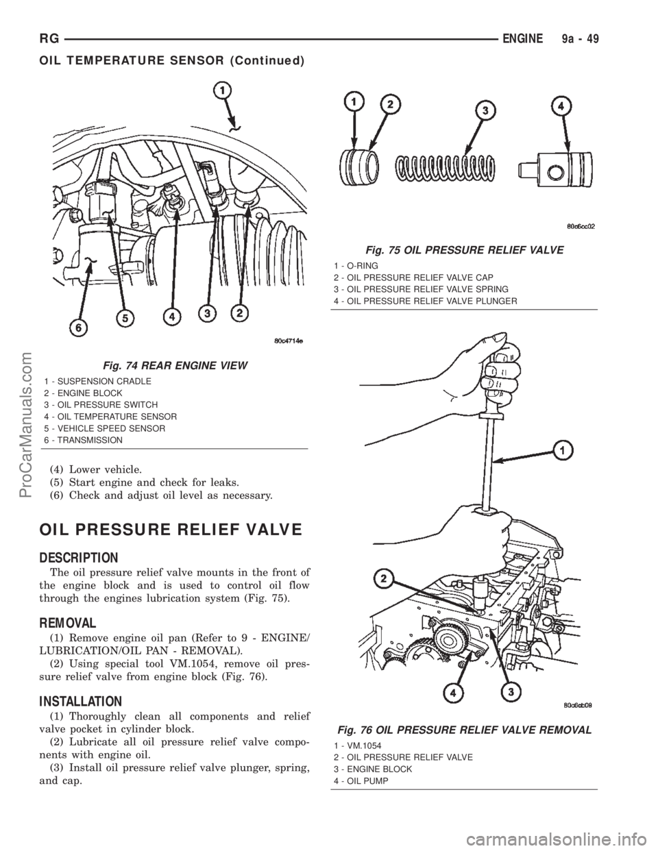
The oil pressure relief valve mounts in the front of
the engine block and is used to control oil flow
through the engines lubrication system (Fig. 75).
REMOVAL
(1) Remove engine oil pan (Refer to 9 - ENGINE/
LUBRICATION/OIL PAN - REMOVAL).
(2) Using special tool VM.1054, remove oil pres-
sure relief valve from engine block (Fig. 76).
INSTALLATION
(1) Thoroughly clean all components and relief
valve pocket in cylinder block.
(2) Lubricate all oil pressure relief valve compo-
nents with engine oil.
(3) Install oil pressure relief valve plunger, spring,
and cap.
Fig. 74 REAR ENGINE VIEW
1 - SUSPENSION CRADLE
2 - ENGINE BLOCK
3 - OIL PRESSURE SWITCH
4 - OIL TEMPERATURE SENSOR
5 - VEHICLE SPEED SENSOR
6 - TRANSMISSION
Fig. 75 OIL PRESSURE RELIEF VALVE
1 - O-RING
2 - OIL PRESSURE RELIEF VALVE CAP
3 - OIL PRESSURE RELIEF VALVE SPRING
4 - OIL PRESSURE RELIEF VALVE PLUNGER
Fig. 76 OIL PRESSURE RELIEF VALVE REMOVAL
1 - VM.1054
2 - OIL PRESSURE RELIEF VALVE
3 - ENGINE BLOCK
4 - OIL PUMP
RGENGINE9a-49
OIL TEMPERATURE SENSOR (Continued)
ProCarManuals.com
Page 1412 of 2399
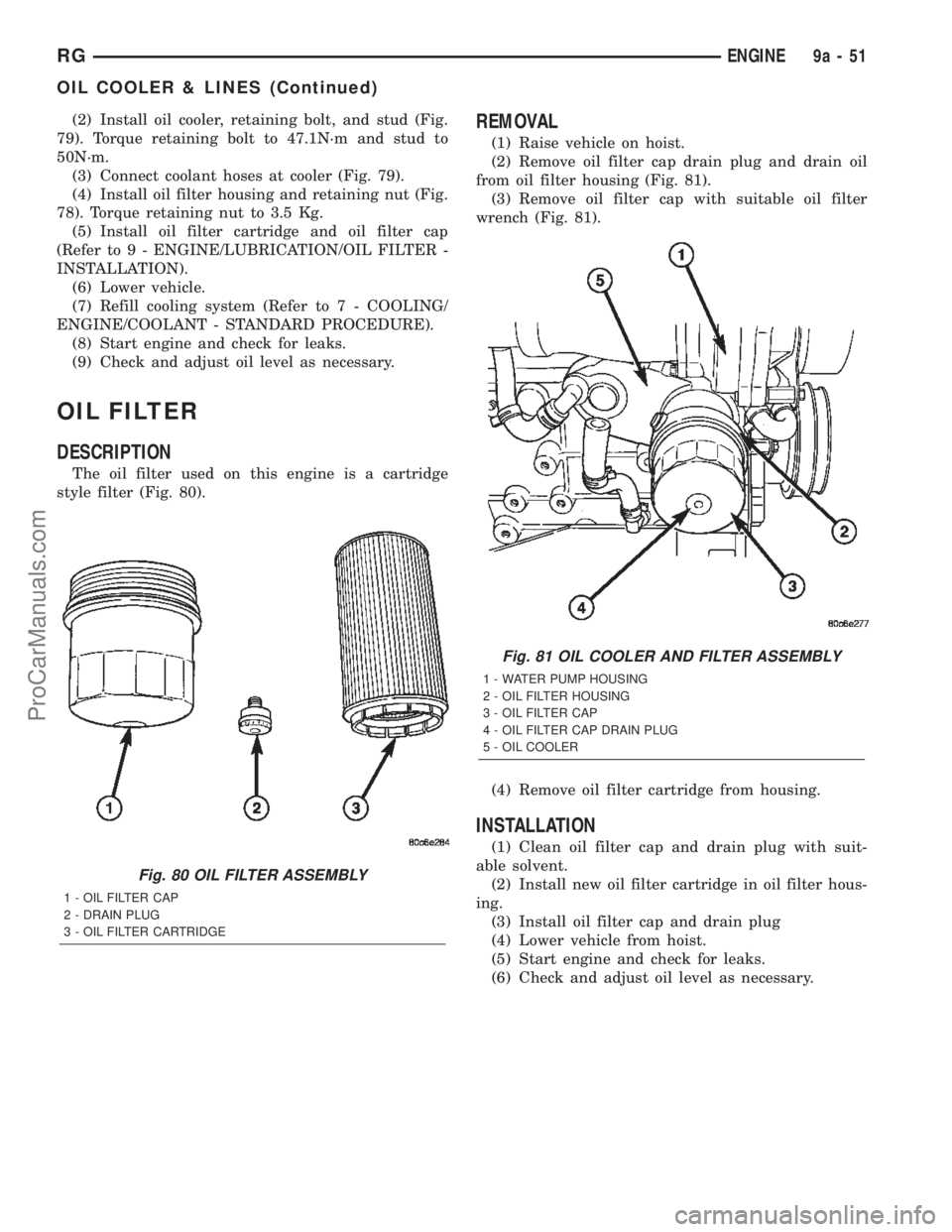
(2) Install oil cooler, retaining bolt, and stud (Fig.
79). Torque retaining bolt to 47.1N´m and stud to
50N´m.
(3) Connect coolant hoses at cooler (Fig. 79).
(4) Install oil filter housing and retaining nut (Fig.
78). Torque retaining nut to 3.5 Kg.
(5) Install oil filter cartridge and oil filter cap
(Refer to 9 - ENGINE/LUBRICATION/OIL FILTER -
INSTALLATION).
(6) Lower vehicle.
(7) Refill cooling system (Refer to 7 - COOLING/
ENGINE/COOLANT - STANDARD PROCEDURE).
(8) Start engine and check for leaks.
(9) Check and adjust oil level as necessary.
OIL FILTER
DESCRIPTION
The oil filter used on this engine is a cartridge
style filter (Fig. 80).
REMOVAL
(1) Raise vehicle on hoist.
(2) Remove oil filter cap drain plug and drain oil
from oil filter housing (Fig. 81).
(3) Remove oil filter cap with suitable oil filter
wrench (Fig. 81).
(4) Remove oil filter cartridge from housing.
INSTALLATION
(1) Clean oil filter cap and drain plug with suit-
able solvent.
(2) Install new oil filter cartridge in oil filter hous-
ing.
(3) Install oil filter cap and drain plug
(4) Lower vehicle from hoist.
(5) Start engine and check for leaks.
(6) Check and adjust oil level as necessary.
Fig. 80 OIL FILTER ASSEMBLY
1 - OIL FILTER CAP
2 - DRAIN PLUG
3 - OIL FILTER CARTRIDGE
Fig. 81 OIL COOLER AND FILTER ASSEMBLY
1 - WATER PUMP HOUSING
2 - OIL FILTER HOUSING
3 - OIL FILTER CAP
4 - OIL FILTER CAP DRAIN PLUG
5 - OIL COOLER
RGENGINE9a-51
OIL COOLER & LINES (Continued)
ProCarManuals.com
Page 1421 of 2399
ADJUSTMENTS
ADJUSTMENT - TIMING BELT TENSIONER
(1) With timing belt outer cover removed and tim-
ing belt installed.
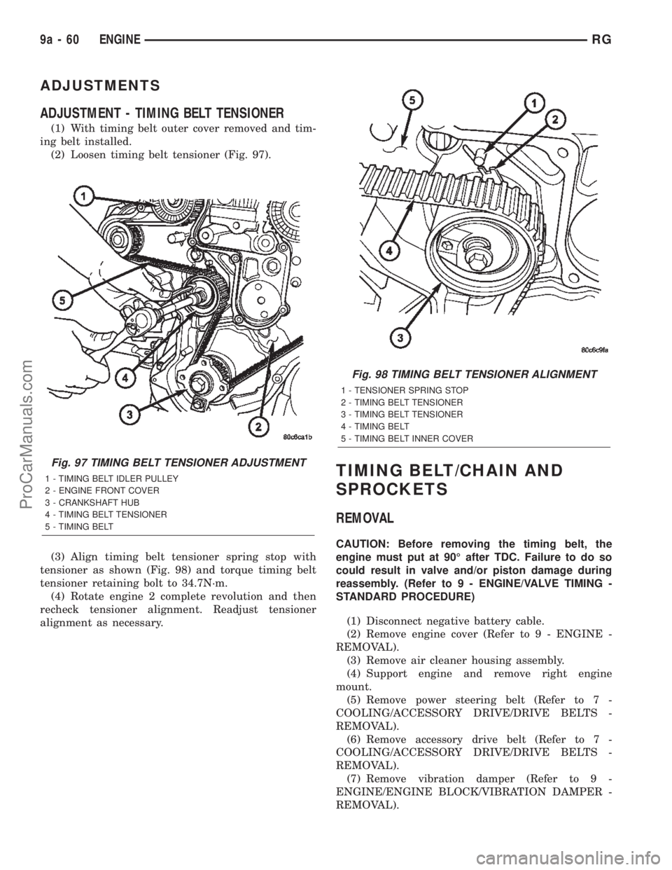
(2) Loosen timing belt tensioner (Fig. 97).
(3) Align timing belt tensioner spring stop with
tensioner as shown (Fig. 98) and torque timing belt
tensioner retaining bolt to 34.7N´m.
(4) Rotate engine 2 complete revolution and then
recheck tensioner alignment. Readjust tensioner
alignment as necessary.
TIMING BELT/CHAIN AND
SPROCKETS
REMOVAL
CAUTION: Before removing the timing belt, the
engine must put at 90É after TDC. Failure to do so
could result in valve and/or piston damage during
reassembly. (Refer to 9 - ENGINE/VALVE TIMING -
STANDARD PROCEDURE)
(1) Disconnect negative battery cable.
(2) Remove engine cover (Refer to 9 - ENGINE -
REMOVAL).
(3) Remove air cleaner housing assembly.
(4) Support engine and remove right engine
mount.
(5) Remove power steering belt (Refer to 7 -
COOLING/ACCESSORY DRIVE/DRIVE BELTS -
REMOVAL).
(6) Remove accessory drive belt (Refer to 7 -
COOLING/ACCESSORY DRIVE/DRIVE BELTS -
REMOVAL).
(7) Remove vibration damper (Refer to 9 -
ENGINE/ENGINE BLOCK/VIBRATION DAMPER -
REMOVAL).
Fig. 97 TIMING BELT TENSIONER ADJUSTMENT
1 - TIMING BELT IDLER PULLEY
2 - ENGINE FRONT COVER
3 - CRANKSHAFT HUB
4 - TIMING BELT TENSIONER
5 - TIMING BELT
Fig. 98 TIMING BELT TENSIONER ALIGNMENT
1 - TENSIONER SPRING STOP
2 - TIMING BELT TENSIONER
3 - TIMING BELT TENSIONER
4 - TIMING BELT
5 - TIMING BELT INNER COVER
9a - 60 ENGINERG
ProCarManuals.com
Page 1424 of 2399
EXHAUST SYSTEM
TABLE OF CONTENTS
page page
EXHAUST SYSTEM
DESCRIPTION..........................1
OPERATION............................2
DIAGNOSIS AND TESTING
DIAGNOSIS AND TESTING - EXCESSIVE
EXHAUST SYSTEM NOISE...............2
DIAGNOSIS AND TESTING - EXHAUST
SYSTEM RESTRICTION CHECK...........2
INSPECTION...........................3
ADJUSTMENTS.........................3
SPECIFICATIONS
TORQUE.............................3
SPECIAL TOOLS
EXHAUST SYSTEM.....................4
CATALYTIC CONVERTER
DESCRIPTION..........................4
OPERATION............................4REMOVAL.............................5
INSPECTION...........................6
INSTALLATION..........................6
CROSS-OVER PIPE - 3.3/3.8L
REMOVAL.............................6
INSTALLATION..........................6
HEAT SHIELDS
DESCRIPTION..........................6
OPERATION............................7
REMOVAL.............................7
INSTALLATION..........................7
MUFFLER
REMOVAL.............................7
INSTALLATION..........................8
RESONATOR
REMOVAL.............................9
INSTALLATION..........................9
EXHAUST SYSTEM
DESCRIPTION
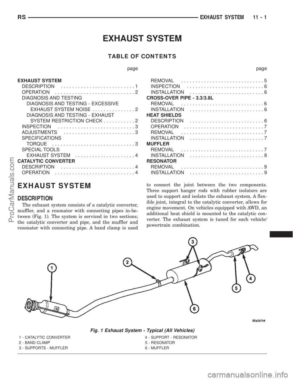
The exhaust system consists of a catalytic converter,
muffler, and a resonator with connecting pipes in-be-
tween (Fig. 1). The system is serviced in two sections;
the catalytic converter and pipe, and the muffler and
resonator with connecting pipe. A band clamp is usedto connect the joint between the two components.
Three support hanger rods with rubber isolators are
used to support and isolate the exhaust system. A flex-
ible joint, integral to the catalytic converter, allows for
engine movement. On vehicles equipped with AWD, an
additional heat shield is mounted to the catalytic con-
verter. The exhaust system is tuned for each vehicle/
powertrain combination.
Fig. 1 Exhaust System - Typical (All Vehicles)
1 - CATALYTIC CONVERTER 4 - SUPPORT - RESONATOR
2 - BAND CLAMP 5 - RESONATOR
3 - SUPPORTS - MUFFLER 6 - MUFFLER
RSEXHAUST SYSTEM11-1
ProCarManuals.com
Page 1425 of 2399
OPERATION
The exhaust system contains, quiets, and cleans
the exhaust gases generated by the engine.
DIAGNOSIS AND TESTING
DIAGNOSIS AND TESTING - EXCESSIVE
EXHAUST SYSTEM NOISE
CONDITION POSSIBLE CAUSES CORRECTION
EXCESSIVE EXHAUST NOISE
(UNDER HOOD)1. Exhaust manifold cracked or
broken.1. Replace manifold.
2. Manifold to cylinder head leak. 2. Tighten manifold and/or replace
gasket.
3. EGR Valve to manifold gasket
leakage.3. Tighten fasteners or replace
gasket.
4. EGR Valve to EGR tube gasket
leakage.4. Tighten fasteners or replace
gasket.
5. EGR tube to manifold tube
leakage.5. Tighten tube nut.
6. Exhaust flex-joint to manifold
leak.6. Tighten joint fasteners and/or
replace gasket.
7. Exhaust flex-joint. 7. Replace catalytic converter
assembly.
8. Pipe and shell noise from front
exhaust pipe.8. Characteristic of single wall pipe.
EXCESSIVE EXHAUST NOISE 1. Leak at exhaust pipe joints. 1. Tighten clamps at leaking joints.
2. Burned or rusted out muffler
assembly or exhaust pipe.2. Replace muffler resonator tailpipe
assembly or exhaust pipe with
catalytic converter assembly.
3. Burned or rusted out resonator. 3. Replace muffler resonator tailpipe
assembly.
4. Restriction in exhaust system. 4. Perform Exhaust System
Restriction Check. Replace
component as necessary.
5. Converter material in muffler. 5. Replace muffler and converter
assemblies. Check fuel injection and
ignition systems for proper
operation.
DIAGNOSIS AND TESTING - EXHAUST SYSTEM
RESTRICTION CHECK
Exhaust system restriction can be checked by mea-
suring back pressure using the DRB IIItand PEP
module pressure tester.WARNING: THE NORMAL OPERATING TEMPERA-
TURE OF THE EXHAUST SYSTEM IS VERY HIGH.
THEREFORE, NEVER WORK AROUND OR ATTEMPT
TO SERVICE ANY PART OF THE EXHAUST SYSTEM
UNTIL IT IS COOLED. SPECIAL CARE SHOULD BE
TAKEN WHEN WORKING NEAR THE CATALYTIC
CONVERTER. THE TEMPERATURE OF THE CON-
VERTER RISES TO A HIGH LEVEL AFTER A SHORT
PERIOD OF ENGINE OPERATION TIME.
11 - 2 EXHAUST SYSTEMRS
EXHAUST SYSTEM (Continued)
ProCarManuals.com
Page 1429 of 2399
INSPECTION
WARNING: THE NORMAL OPERATING TEMPERA-
TURE OF THE EXHAUST SYSTEM IS VERY HIGH.
THEREFORE, NEVER ATTEMPT TO SERVICE ANY
PART OF THE EXHAUST SYSTEM UNTIL IT IS
COOLED. SPECIAL CARE SHOULD BE TAKEN
WHEN WORKING NEAR THE CATALYTIC CON-
VERTER. THE TEMPERATURE OF THE CONVERTER
RISES TO A HIGH LEVEL AFTER A SHORT PERIOD
OF ENGINE OPERATION TIME.
Check catalytic converter for a flow restriction.
(Refer to 11 - EXHAUST SYSTEM - DIAGNOSIS
AND TESTING) Exhaust System Restriction Check
for procedure.
Visually inspect the catalytic converter element by
using a borescope or equivalent. Remove oxygen sen-
sor(s) and insert borescope. If borescope is not avail-
able, remove converter and inspect element using a
flashlight. Inspect element for cracked or melted sub-
strate.
NOTE: Before replacing a catalytic converter, deter-
mine the root cause of failure. Most catalytic con-
verter failures are caused by air, fuel or ignition
problems. (Refer to Appropriate Diagnostic Informa-
tion) for test procedures.
INSTALLATION
(1) Position new gasket onto the manifold flange
and install catalytic converter (Fig. 5). Tighten fas-
teners to 37 N´m (325 in. lbs.).
NOTE: Be careful not to twist or kink the oxygen
sensor wires.
(2) Install (if removed) and connect the down-
stream oxygen sensor (Fig. 4).
(3) Install the muffler/resonator assembly. (Refer
to 11 - EXHAUST SYSTEM/MUFFLER - INSTALLA-
TION)
CROSS-OVER PIPE - 3.3/3.8L
REMOVAL
(1) Disconnect negative cable from battery.
(2) Remove the fasteners attaching the left bank
manifold connection to cross-over pipe (Fig. 6).
(3) Raise vehicle and remove the left front wheel.
(4) Access the lower right bank pipe connection
fastener through the left front wheel opening using a
long ratchet extension. Loosen and remove the lower
fastener.(5) Remove the upper right bank pipe connection
fastener by accessing though the catalytic converter
floor pan tunnel.
(6) Lower the vehicle.
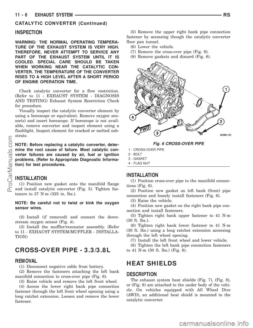
(7) Remove the cross-over pipe (Fig. 6).
(8) Remove gaskets and discard (Fig. 6).
INSTALLATION
(1) Position cross-over pipe to the manifold connec-
tions (Fig. 6).
(2) Position new gasket on left bank (front) pipe
connection and loosely install fasteners (Fig. 6).
(3) Raise the vehicle.
(4) Position new gasket on the right bank pipe con-
nection and install fasteners.
(5) Tighten right bank upper fastener to 41 N´m
(30 ft. lbs.).
(6) Tighten right bank lower fastener to 41 N´m
(30 ft. lbs.) using a long ratchet extension accessing
through the left wheel opening.
(7) Install the left front wheel and lower vehicle.
(8) Tighten the left bank pipe connection fasteners
to 41 N´m (30 ft. lbs.) (Fig. 6).
HEAT SHIELDS
DESCRIPTION
The exhaust system heat shields (Fig. 7), (Fig. 8),
or (Fig. 9) are attached to the under body of the vehi-
cle. On vehicles equipped with All Wheel Dive
(AWD), an additional heat shield is mounted to the
catalytic converter.
Fig. 6 CROSS-OVER PIPE
1 - CROSS-OVER PIPE
2 - BOLT
3 - GASKET
4 - FLAG NUT
11 - 6 EXHAUST SYSTEMRS
CATALYTIC CONVERTER (Continued)
ProCarManuals.com
Page 1443 of 2399
(3) Install the six nuts attaching rear bumper rein-
forcement to frame rail extensions and tighten to 27
N´m (20 ft. lbs.) torque (Fig. 4).
(4) Install rear bumper fascia. (Refer to 13 -
FRAMES & BUMPERS/BUMPERS/REAR FASCIA -
INSTALLATION).
REAR FASCIA - SCUFF PAD
REMOVAL
The scuff pad may not be salvageable during the
removal process. The scuff pad should be replaced if
damaged or broken. Check availability before servic-
ing. The scuff pad serviceability is improved if the
rear fascia is to be removed for service.
NOTE: If the rear fascia is to be removed for other
service issues or If the scuff pad is to be reused
use the steps below.
(1) Remove rear bumper fascia.(Refer to 13 -
FRAMES & BUMPERS/BUMPERS/REAR FASCIA -
REMOVAL)
(2) Using a trim stick, pry up the rear edge of the
scuff pad while squeezing the rear locking tabs from
underneath the fascia to release the rear edge of
scuff pad from the rear bumper fascia. Pull the scuff
pad up and squeeze the remaining tabs to release the
remaining of the scuff pad. (Fig. 5).
NOTE: If the rear fascia is to not to be removed for
other service issues use the step below.
(3) Using a trim stick, pry up the rear edge of the
scuff pad to release tabs from the rear bumper fascia
and pull scuff pad to release the forward tabs (Fig.
5).
INSTALLATION
(1) Verify that there are fifteen slots in the fascia.
(2) Place scuff pad in position (Fig. 5).
(3) Align and insert the center forward tab.
(4) Align the remaining tabs and press into the
slots, starting in the center and working outboard.
(5) Assure all tabs are fully engaged into the fas-
cia.(6) If rear bumper fascia has been removed install.
(Refer to 13 - FRAME & BUMPERS/BUMPERS/
REAR FASCIA - INSTALLATION).
FRAME
SPECIFICATIONS
FRAME DIMENSIONS
Frame dimensions are listed in metric scale. All
dimensions are from center to center of Principal
Locating Point (PLP), or from center to center of PLP
and fastener location.
VEHICLE PREPARATION
Position the vehicle on a frame alignment rack,
refer to instructions provided with equipment being
used. Adjust the vehicle PLP heights to the specified
dimension above the work surface (datum line). Ver-
tical dimensions can be taken from the datum line to
the locations indicated were applicable.
INDEX
DESCRIPTION FIGURE
CROSSMEMBER DIMENSIONS 6
ENGINE BOX - TOP VIEW 7
ENGINE COMPARTMENT AND FRAME RAIL - SIDE VIEW 8
FULL VEHICLE - BOTTOM VIEW 9
Fig. 5 SCUFF PAD
1 - SCUFF PAD
2 - TABS
13 - 4 FRAME & BUMPERSRS
REAR BUMPER REINFORCEMENT (Continued)
ProCarManuals.com
Page 1453 of 2399
FUEL DELIVERY
DESCRIPTION
DESCRIPTION
The front wheel drive car uses a plastic fuel tank
located rear center of the vehicle.
The Fuel Delivery System consists of: the following
items:
²Electric fuel pump module
²Fuel filter
²Tubes/lines/hoses
²Fuel injectors
The in-tank fuel pump module contains the fuel
pump. The pump is serviced as part of the fuel pump
module. Refer to Fuel Pump Module.
The fuel filter is replaceable, it is mounted on the
outside, on top of, the fuel tank. Refer to the Main-
tenance Schedules in the Introduction section of this
manual for recommended fuel filter replacement
intervals.
DESCRIPTION - FFV REPLACEMENT PARTS
Many components in a Flexible Fuel Vehicle (FFV)
are designed to be compatible with ethanol. Always
be sure that the vehicle is serviced with correct etha-
nol compatible parts.
CAUTION: Replacing fuel system components with
non-ethanol compatible components can damage
your vehicle and may void the warranty.
OPERATION
The fuel system provides fuel pressure by an
in-tank pump module. The PCM controls the opera-
tion of the fuel system by providing battery voltage
to the fuel pump through the fuel pump relay. The
PCM requires only three inputs and a good ground to
operate the fuel pump relay. The three inputs are:²Ignition voltage
²Crankshaft Position (CKP) sensor
²Camshaft Position (CMP) sensor
DIAGNOSIS AND TESTING - FUEL DELIVERY
SYSTEM
(Refer to Appropriate Diagnostic Information)
STANDARD PROCEDURE
STANDARD PROCEDURE - FUEL SYSTEM
PRESSURE RELEASE PROCEDURE
(1) Remove Fuel Pump relay from Power Distribu-
tion Center (PDC). For location of relay, refer to label
on underside of PDC cover.
(2) Start and run engine until it stalls.
(3) Attempt restarting engine until it will no
longer run.
(4) Turn ignition key to OFF position.
(5) Return fuel pump relay to PDC.
(6) One or more Diagnostic Trouble Codes (DTC's)
may have been stored in PCM memory due to fuel
pump relay removal. The DRB IIItscan tool must be
used to erase a DTC.
STANDARD PROCEDURE - DRAINING FUEL
TANK
(1) Release fuel system pressure, refer to the Fuel
System Release Procedure in this section.
(2) Insert a 1/4 inch siphon (max. O. D. 5/16) hose
from a portable fuel siphoning tank through the fuel
filler neck opening into the fuel tank. Hose most
have a 30 degree angle cut on the end to bypass the
check valve in the end of the filler neck. Refer to the
siphoning tank's Manufacturing Instructions.
(3) Drain fuel from fuel tank into siphoning tank.
14 - 2 FUEL DELIVERYRS
ProCarManuals.com