2002 CHRYSLER CARAVAN check engine
[x] Cancel search: check enginePage 1350 of 2399
INSPECTION
Check manifold for:
²Damage and cracks.
²Mounting surface distortion by using a straight-
edge and thickness gauge.
INSTALLATION - UPPER INTAKE MANIFOLD
(1) If the following components were removed from
manifold, install and tighten to specifications:
CAUTION: The special screws used for the compos-
ite manifold attached components must be installed
slowly using hand tools only. This requirement is to
prevent the melting of material that causes stripped
threads. If threads become stripped, an oversize
repair screw is available. For more information and
procedure (Refer to 9 - ENGINE/MANIFOLDS/IN-
TAKE MANIFOLD - STANDARD PROCEDURE - MAN-
IFOLD STRIPPED THREAD REPAIR).²MAP sensor - 1.7 N´m (15 in. lbs.)
²Throttle cable bracket - 5.6 N´m (50 in. lbs.)
(2) Remove covering on lower intake manifold and
clean surfaces.
(3) Inspect manifold gasket condition. Gaskets can
be re-used, if not damaged. To replace, remove gasket
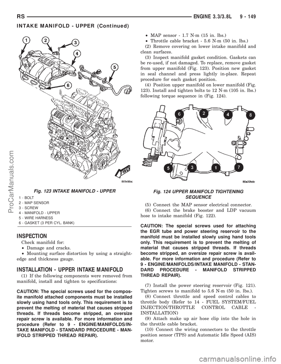
from upper manifold (Fig. 123). Position new gasket
in seal channel and press lightly in-place. Repeat
procedure for each gasket position.
(4) Position upper manifold on lower manifold (Fig.
123). Install and tighten bolts to 12 N´m (105 in. lbs.)
following torque sequence in (Fig. 124).
(5) Connect the MAP sensor electrical connector.
(6) Connect the brake booster and LDP vacuum
hose to intake manifold (Fig. 122).
CAUTION: The special screws used for attaching
the EGR tube and power steering reservoir to the
manifold must be installed slowly using hand tools
only. This requirement is to prevent the melting of
material that causes stripped threads. If threads
become stripped, an oversize repair screw is avail-
able. For more information and procedure (Refer to
9 - ENGINE/MANIFOLDS/INTAKE MANIFOLD - STAN-
DARD PROCEDURE - MANIFOLD STRIPPED
THREAD REPAIR).
(7) Install the power steering reservoir (Fig. 121).
Tighten screws to manifold to 5.6 N´m (50 in. lbs.).
(8) Connect throttle and speed control cables to
throttle body (Refer to 14 - FUEL SYSTEM/FUEL
INJECTION/THROTTLE CONTROL CABLE -
INSTALLATION)
(9) Attach make up air hose clip into the hole in
the throttle cable bracket.
(10) Connect the wiring connectors to the throttle
position sensor (TPS) and Automatic Idle Speed (AIS)
motor.
Fig. 123 INTAKE MANIFOLD - UPPER
1 - BOLT
2 - MAP SENSOR
3 - SCREW
4 - MANIFOLD - UPPER
5 - WIRE HARNESS
6 - GASKET (3 PER CYL. BANK)
Fig. 124 UPPER MANIFOLD TIGHTENING
SEQUENCE
RSENGINE 3.3/3.8L9 - 149
INTAKE MANIFOLD - UPPER (Continued)
ProCarManuals.com
Page 1351 of 2399
(11) Install air cleaner and air inlet hose assembly.
(12) Connect the inlet air temperature (IAT) sen-
sor electrical connector.
(13) Connect battery negative cable.
INTAKE MANIFOLD - LOWER
REMOVAL - LOWER INTAKE MANIFOLD
(1) Perform fuel system pressure release procedure
(before attempting any repairs).(Refer to 14 -
FUEL SYSTEM/FUEL DELIVERY - STANDARD
PROCEDURE)
(2) Drain the cooling system. (Refer to 7 - COOL-
ING - STANDARD PROCEDURE)
(3) Remove the upper intake manifold. (Refer to 9
- ENGINE/MANIFOLDS/INTAKE MANIFOLD -
REMOVAL)
(4) Remove the fuel line. (Refer to 14 - FUEL SYS-
TEM/FUEL DELIVERY/FUEL LINES - STANDARD
PROCEDURE) (Refer to 14 - FUEL SYSTEM/FUEL
DELIVERY/QUICK CONNECT FITTING - STAN-
DARD PROCEDURE)
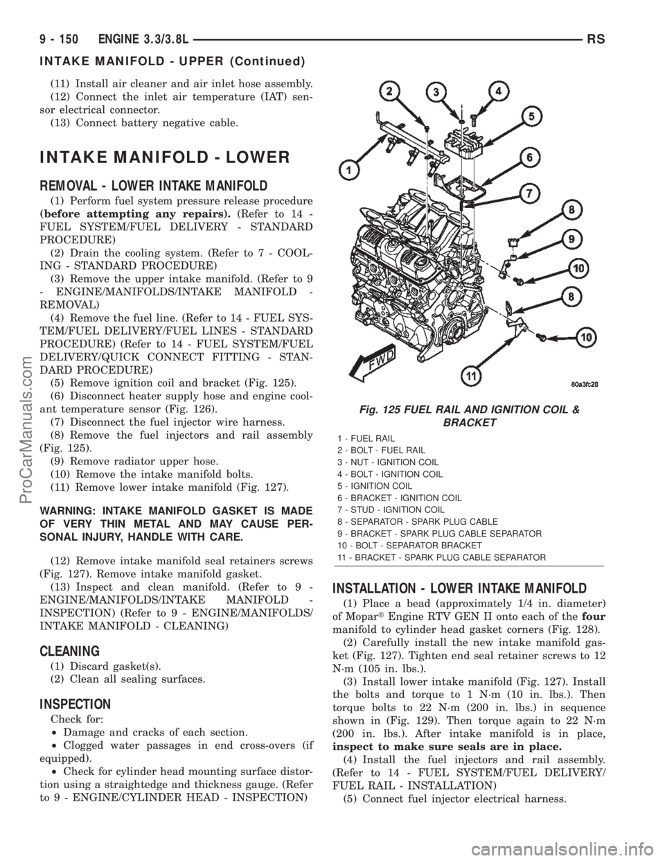
(5) Remove ignition coil and bracket (Fig. 125).
(6) Disconnect heater supply hose and engine cool-
ant temperature sensor (Fig. 126).
(7) Disconnect the fuel injector wire harness.
(8) Remove the fuel injectors and rail assembly
(Fig. 125).
(9) Remove radiator upper hose.
(10) Remove the intake manifold bolts.
(11) Remove lower intake manifold (Fig. 127).
WARNING: INTAKE MANIFOLD GASKET IS MADE
OF VERY THIN METAL AND MAY CAUSE PER-
SONAL INJURY, HANDLE WITH CARE.
(12) Remove intake manifold seal retainers screws
(Fig. 127). Remove intake manifold gasket.
(13) Inspect and clean manifold. (Refer to 9 -
ENGINE/MANIFOLDS/INTAKE MANIFOLD -
INSPECTION) (Refer to 9 - ENGINE/MANIFOLDS/
INTAKE MANIFOLD - CLEANING)
CLEANING
(1) Discard gasket(s).
(2) Clean all sealing surfaces.
INSPECTION
Check for:
²Damage and cracks of each section.
²Clogged water passages in end cross-overs (if
equipped).
²Check for cylinder head mounting surface distor-
tion using a straightedge and thickness gauge. (Refer
to 9 - ENGINE/CYLINDER HEAD - INSPECTION)
INSTALLATION - LOWER INTAKE MANIFOLD
(1) Place a bead (approximately 1/4 in. diameter)
of MopartEngine RTV GEN II onto each of thefour
manifold to cylinder head gasket corners (Fig. 128).
(2) Carefully install the new intake manifold gas-
ket (Fig. 127). Tighten end seal retainer screws to 12
N´m (105 in. lbs.).
(3) Install lower intake manifold (Fig. 127). Install
the bolts and torque to 1 N´m (10 in. lbs.). Then
torque bolts to 22 N´m (200 in. lbs.) in sequence
shown in (Fig. 129). Then torque again to 22 N´m
(200 in. lbs.). After intake manifold is in place,
inspect to make sure seals are in place.
(4) Install the fuel injectors and rail assembly.
(Refer to 14 - FUEL SYSTEM/FUEL DELIVERY/
FUEL RAIL - INSTALLATION)
(5) Connect fuel injector electrical harness.
Fig. 125 FUEL RAIL AND IGNITION COIL &
BRACKET
1 - FUEL RAIL
2 - BOLT - FUEL RAIL
3 - NUT - IGNITION COIL
4 - BOLT - IGNITION COIL
5 - IGNITION COIL
6 - BRACKET - IGNITION COIL
7 - STUD - IGNITION COIL
8 - SEPARATOR - SPARK PLUG CABLE
9 - BRACKET - SPARK PLUG CABLE SEPARATOR
10 - BOLT - SEPARATOR BRACKET
11 - BRACKET - SPARK PLUG CABLE SEPARATOR
9 - 150 ENGINE 3.3/3.8LRS
INTAKE MANIFOLD - UPPER (Continued)
ProCarManuals.com
Page 1354 of 2399
INSPECTION
Inspect exhaust manifolds for damage or cracks
and check distortion of the cylinder head mountingsurface and exhaust crossover mounting surface with
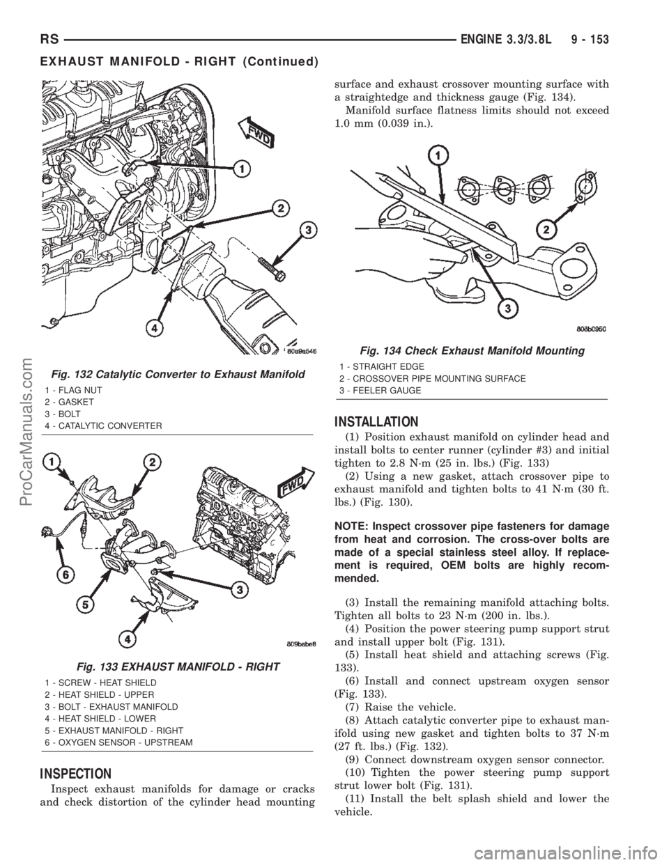
a straightedge and thickness gauge (Fig. 134).
Manifold surface flatness limits should not exceed
1.0 mm (0.039 in.).
INSTALLATION
(1) Position exhaust manifold on cylinder head and
install bolts to center runner (cylinder #3) and initial
tighten to 2.8 N´m (25 in. lbs.) (Fig. 133)
(2) Using a new gasket, attach crossover pipe to
exhaust manifold and tighten bolts to 41 N´m (30 ft.
lbs.) (Fig. 130).
NOTE: Inspect crossover pipe fasteners for damage
from heat and corrosion. The cross-over bolts are
made of a special stainless steel alloy. If replace-
ment is required, OEM bolts are highly recom-
mended.
(3) Install the remaining manifold attaching bolts.
Tighten all bolts to 23 N´m (200 in. lbs.).
(4) Position the power steering pump support strut
and install upper bolt (Fig. 131).
(5) Install heat shield and attaching screws (Fig.
133).
(6) Install and connect upstream oxygen sensor
(Fig. 133).
(7) Raise the vehicle.
(8) Attach catalytic converter pipe to exhaust man-
ifold using new gasket and tighten bolts to 37 N´m
(27 ft. lbs.) (Fig. 132).
(9) Connect downstream oxygen sensor connector.
(10) Tighten the power steering pump support
strut lower bolt (Fig. 131).
(11) Install the belt splash shield and lower the
vehicle.
Fig. 132 Catalytic Converter to Exhaust Manifold
1 - FLAG NUT
2 - GASKET
3 - BOLT
4 - CATALYTIC CONVERTER
Fig. 133 EXHAUST MANIFOLD - RIGHT
1 - SCREW - HEAT SHIELD
2 - HEAT SHIELD - UPPER
3 - BOLT - EXHAUST MANIFOLD
4 - HEAT SHIELD - LOWER
5 - EXHAUST MANIFOLD - RIGHT
6 - OXYGEN SENSOR - UPSTREAM
Fig. 134 Check Exhaust Manifold Mounting
1 - STRAIGHT EDGE
2 - CROSSOVER PIPE MOUNTING SURFACE
3 - FEELER GAUGE
RSENGINE 3.3/3.8L9 - 153
EXHAUST MANIFOLD - RIGHT (Continued)
ProCarManuals.com
Page 1355 of 2399
(12) Install the wiper module. (Refer to 8 - ELEC-
TRICAL/WIPERS/WASHERS/WIPER MODULE -
INSTALLATION)
(13) Connect battery negative cable.
EXHAUST MANIFOLD - LEFT
REMOVAL
(1) Disconnect battery negative cable.
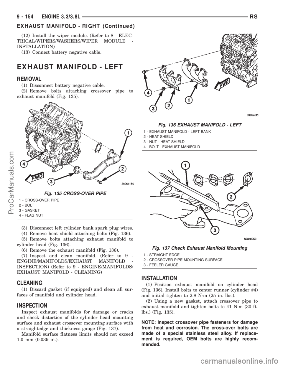
(2) Remove bolts attaching crossover pipe to
exhaust manifold (Fig. 135).
(3) Disconnect left cylinder bank spark plug wires.
(4) Remove heat shield attaching bolts (Fig. 136).
(5) Remove bolts attaching exhaust manifold to
cylinder head (Fig. 136).
(6) Remove the exhaust manifold (Fig. 136).
(7) Inspect and clean manifold. (Refer to 9 -
ENGINE/MANIFOLDS/EXHAUST MANIFOLD -
INSPECTION) (Refer to 9 - ENGINE/MANIFOLDS/
EXHAUST MANIFOLD - CLEANING)
CLEANING
(1) Discard gasket (if equipped) and clean all sur-
faces of manifold and cylinder head.
INSPECTION
Inspect exhaust manifolds for damage or cracks
and check distortion of the cylinder head mounting
surface and exhaust crossover mounting surface with
a straightedge and thickness gauge (Fig. 137).
Manifold surface flatness limits should not exceed
1.0 mm (0.039 in.).
INSTALLATION
(1) Position exhaust manifold on cylinder head
(Fig. 136). Install bolts to center runner (cylinder #4)
and initial tighten to 2.8 N´m (25 in. lbs.).
(2) Using a new gasket, attach crossover pipe to
exhaust manifold and tighten bolts to 41 N´m (30 ft.
lbs.) (Fig. 135).
NOTE: Inspect crossover pipe fasteners for damage
from heat and corrosion. The cross-over bolts are
made of a special stainless steel alloy. If replace-
ment is required, OEM bolts are highly recom-
mended.
Fig. 135 CROSS-OVER PIPE
1 - CROSS-OVER PIPE
2 - BOLT
3 - GASKET
4 - FLAG NUT
Fig. 136 EXHAUST MANIFOLD - LEFT
1 - EXHAUST MANIFOLD - LEFT BANK
2 - HEAT SHIELD
3 - NUT - HEAT SHIELD
4 - BOLT - EXHAUST MANIFOLD
Fig. 137 Check Exhaust Manifold Mounting
1 - STRAIGHT EDGE
2 - CROSSOVER PIPE MOUNTING SURFACE
3 - FEELER GAUGE
9 - 154 ENGINE 3.3/3.8LRS
EXHAUST MANIFOLD - RIGHT (Continued)
ProCarManuals.com
Page 1361 of 2399
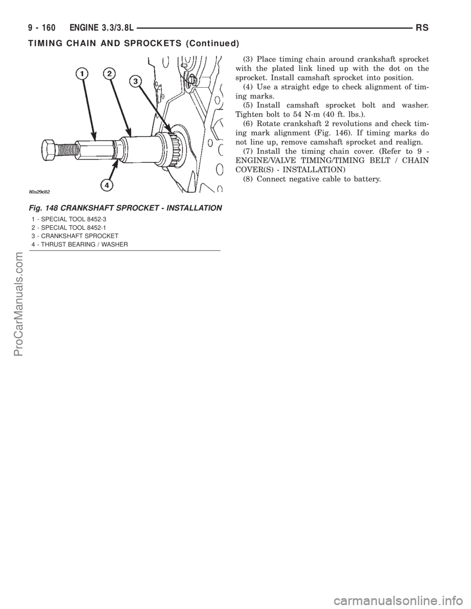
(3) Place timing chain around crankshaft sprocket
with the plated link lined up with the dot on the
sprocket. Install camshaft sprocket into position.
(4) Use a straight edge to check alignment of tim-
ing marks.
(5) Install camshaft sprocket bolt and washer.
Tighten bolt to 54 N´m (40 ft. lbs.).
(6) Rotate crankshaft 2 revolutions and check tim-
ing mark alignment (Fig. 146). If timing marks do
not line up, remove camshaft sprocket and realign.
(7) Install the timing chain cover. (Refer to 9 -
ENGINE/VALVE TIMING/TIMING BELT / CHAIN
COVER(S) - INSTALLATION)
(8) Connect negative cable to battery.
Fig. 148 CRANKSHAFT SPROCKET - INSTALLATION
1 - SPECIAL TOOL 8452-3
2 - SPECIAL TOOL 8452-1
3 - CRANKSHAFT SPROCKET
4 - THRUST BEARING / WASHER
9 - 160 ENGINE 3.3/3.8LRS
TIMING CHAIN AND SPROCKETS (Continued)
ProCarManuals.com
Page 1362 of 2399
ENGINE
TABLE OF CONTENTS
page page
ENGINE 2.5L TURBO DIESEL
DESCRIPTION
DESCRIPTION - 2.5L COMMON RAIL
DIESEL ENGINE.......................2
DESCRIPTION - ENGINE COVER..........3
REMOVAL
REMOVAL - 2.5L DIESEL ENGINE..........3
REMOVAL - ENGINE COVER.............6
INSTALLATION
INSTALLATION - 2.5L TURBO DIESEL
ENGINE..............................7
INSTALLATION - ENGINE COVER..........7
SPECIFICATIONS
SPECIFICATIONS - 2.5L COMMON RAIL
DIESEL ENGINE.......................8
SPECIFICATIONS - TORQUE............10
SPECIAL TOOLS.......................12
CYLINDER HEAD
STANDARD PROCEDURE
STANDARD PROCEDURE - VALVE
SERVICE............................17
STANDARD PROCEDURE - MEASURING
PISTON PROTRUSION.................18
REMOVAL.............................19
CLEANING............................21
INSPECTION..........................21
INSTALLATION.........................21
CAMSHAFT(S)
DESCRIPTION.........................22
OPERATION...........................22
REMOVAL.............................22
INSTALLATION.........................23
CYLINDER HEAD COVER(S)
DESCRIPTION.........................24
REMOVAL.............................24
INSTALLATION.........................25
CAMSHAFT OIL SEAL(S)
REMOVAL.............................27
INSTALLATION.........................27
ROCKER ARMS
DESCRIPTION.........................27
OPERATION...........................27
REMOVAL.............................27
INSTALLATION.........................28
HYDRAULIC LIFTERS
DESCRIPTION.........................29
REMOVAL.............................29
INSPECTION..........................30
INSTALLATION.........................30ENGINE BLOCK
DESCRIPTION.........................30
CRANKSHAFT
DESCRIPTION.........................30
OPERATION...........................30
STANDARD PROCEDURE - CHECKING
CRANKSHAFT END PLAY...............31
REMOVAL.............................31
INSTALLATION.........................32
CYLINDER LINERS
DESCRIPTION.........................33
REMOVAL.............................33
INSPECTION..........................34
INSTALLATION.........................34
INTERNAL VACUUM PUMP
DESCRIPTION.........................35
REMOVAL.............................35
INSTALLATION.........................35
PISTON & CONNECTING ROD
DESCRIPTION.........................36
STANDARD PROCEDURE - PISTON RING
FITTING.............................36
REMOVAL.............................36
INSPECTION..........................38
INSTALLATION.........................39
CRANKSHAFT OIL SEAL - FRONT
REMOVAL.............................41
INSTALLATION.........................41
VIBRATION DAMPER
REMOVAL.............................42
INSTALLATION.........................42
ENGINE COVER - FRONT
DESCRIPTION.........................43
REMOVAL.............................43
INSTALLATION.........................43
CRANKSHAFT MAIN BEARINGS
REMOVAL.............................44
INSTALLATION.........................45
CRANKSHAFT OIL SEAL - REAR
REMOVAL.............................46
INSTALLATION.........................46
OIL PAN
REMOVAL.............................46
INSTALLATION.........................46
OIL PUMP
REMOVAL
REMOVAL...........................47
REMOVAL...........................47
RGENGINE9a-1
ProCarManuals.com
Page 1366 of 2399
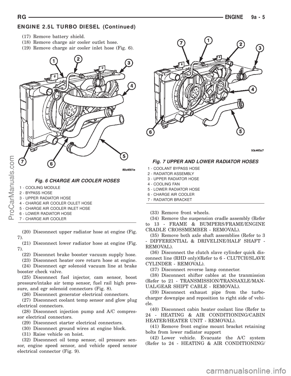
(17) Remove battery shield.
(18) Remove charge air cooler outlet hose.
(19) Remove charge air cooler inlet hose (Fig. 6).
(20) Disconnect upper radiator hose at engine (Fig.
7).
(21) Disconnect lower radiator hose at engine (Fig.
7).
(22) Disconnet brake booster vacuum supply hose.
(23) Disconnect heater core return hose at engine.
(24) Disconnect egr solenoid vacuum line at brake
booster check valve.
(25) Disconnect fuel injector, cam sensor, boost
pressure/intake air temp sensor, fuel rail high pres-
sure, and egr solenoid connectors (Fig. 8).
(26) Disconnect generator electrical connectors.
(27) Disconnect coolant temp sensor and glow plug
electrical connectors.
(28) Disconnect injection pump and A/C compres-
sor electrical connectors.
(29) Disconnect starter electrical connectors.
(30) Disconnect ground wires at engine block.
(31) Raise vehicle on hoist.
(32) Disconnect oil temp sensor, oil pressure sen-
sor, engine speed sensor, and vehicle speed sensor
electrical connector (Fig. 9).(33) Remove front wheels.
(34) Remove the suspension cradle assembly (Refer
to 13 - FRAME & BUMPERS/FRAME/ENGINE
CRADLE CROSSMEMBER - REMOVAL).
(35) Remove both axle shaft assemblies (Refer to 3
- DIFFERENTIAL & DRIVELINE/HALF SHAFT -
REMOVAL).
(36) Disconnect the clutch slave cylinder quick dis-
connect line (RHD only)(Refer to 6 - CLUTCH/SLAVE
CYLINDER - REMOVAL).
(37) Disconnect reverse lamp connector.
(38) Disconnect shifter cables at the tranmission
(Refer to 21 - TRANSMISSION/TRANSAXLE/MAN-
UAL/GEAR SHIFT CABLE - REMOVAL).
(39) Disconnect exhaust pipe from the turbo-
charger downpipe and reposition to right side of vehi-
cle.
(40) Disconnect cabin heater coolant line (Refer to
24 - HEATING & AIR CONDITIONING/CABIN
HEATER/HEATER UNIT - REMOVAL).
(41) Remove front engine mount bracket retaining
bolts from lower radiator support
(42) Lower vehicle. Evacuate the A/C system
(Refer to 24 - HEATING & AIR CONDITIONING/
Fig. 6 CHARGE AIR COOLER HOSES
1 - COOLING MODULE
2 - BYPASS HOSE
3 - UPPER RADIATOR HOSE
4 - CHARGE AIR COOLER OULET HOSE
5 - CHARGE AIR COOLER INLET HOSE
6 - LOWER RADIATOR HOSE
7 - CHARGE AIR COOLER
Fig. 7 UPPER AND LOWER RADIATOR HOSES
1 - COOLANT BYPASS HOSE
2 - RADIATOR ASSEMBLY
3 - UPPER RADIATOR HOSE
4 - COOLING FAN
5 - LOWER RADIATOR HOSE
6 - CHARGE AIR COOLER
7 - RADIATOR BRACKET
RGENGINE9a-5
ENGINE 2.5L TURBO DIESEL (Continued)
ProCarManuals.com
Page 1378 of 2399
CYLINDER HEAD
STANDARD PROCEDURE
STANDARD PROCEDURE - VALVE SERVICE
This procedure is done with the engine cylinder
head removed from the block.
DISASSEMBLY
(1) Remove the engine cylinder head from the cyl-
inder block. Refer to cylinder head removal and
installation in this section.
(2) Use Valve Spring Compressor Tool and com-
press each valve spring.
(3) Remove the valve locks, retainers, and springs.
(4) Use an Arkansas smooth stone or a jewelers
file to remove any burrs on the top of the valve stem,
especially around the groove for the locks.
(5) Remove the valves, and place them in a rack in
the same order as removed.
VALVE CLEANING
(1) Clean all carbon deposits from the combustion
chambers, valve ports, valve stems, valve stem
guides and head.
(2) Clean all grime and gasket material from the
engine cylinder head machined gasket surface.
INSPECTION
(1) Inspect for cracks in the combustion chambers
and valve ports.
(2) Inspect for cracks on the exhaust seat.
(3) Inspect for cracks in the gasket surface at each
coolant passage.
(4) Inspect valves for burned, cracked or warped
heads.
(5) Inspect for scuffed or bent valve stems.
(6) Replace valves displaying any damage.
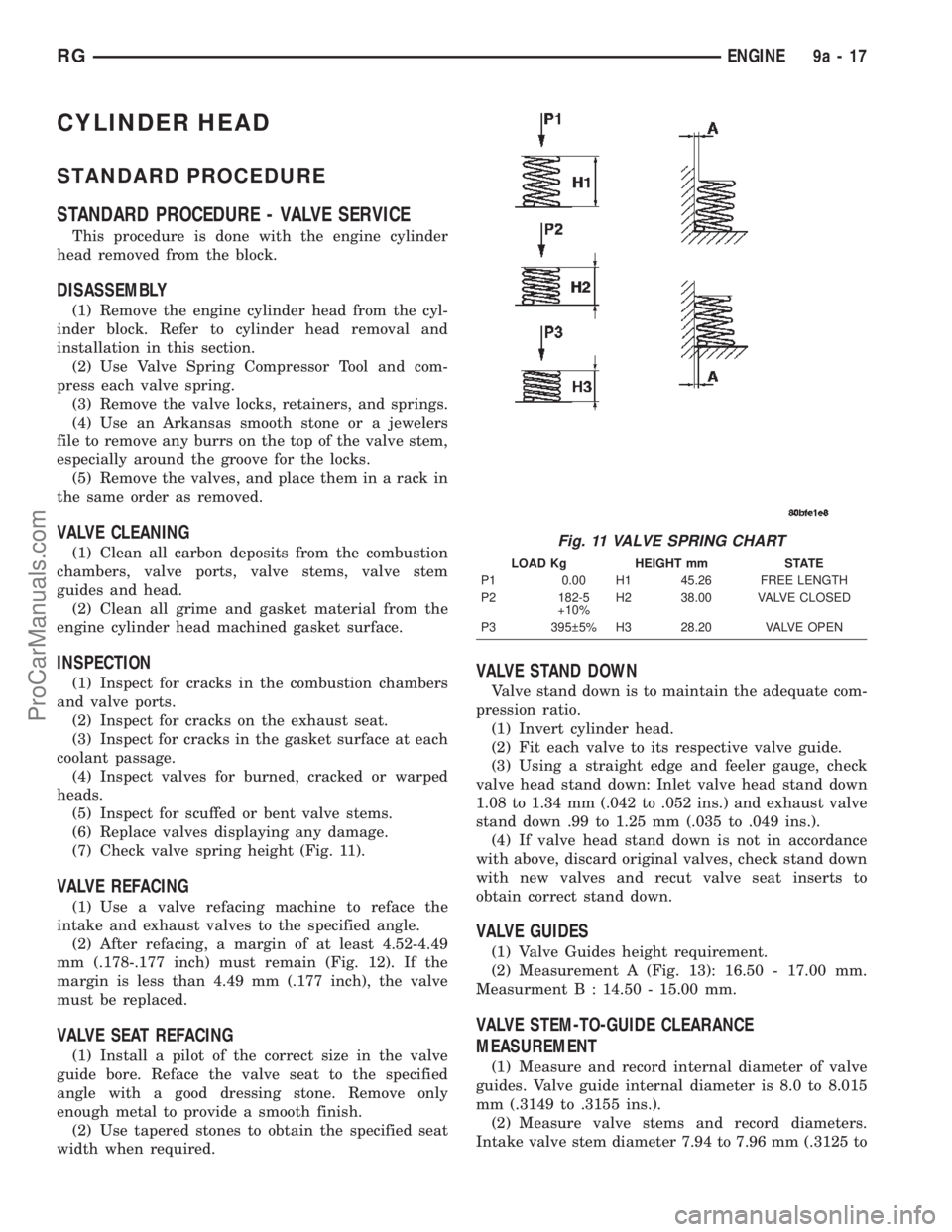
(7) Check valve spring height (Fig. 11).
VALVE REFACING
(1) Use a valve refacing machine to reface the
intake and exhaust valves to the specified angle.
(2) After refacing, a margin of at least 4.52-4.49
mm (.178-.177 inch) must remain (Fig. 12). If the
margin is less than 4.49 mm (.177 inch), the valve
must be replaced.
VALVE SEAT REFACING
(1) Install a pilot of the correct size in the valve
guide bore. Reface the valve seat to the specified
angle with a good dressing stone. Remove only
enough metal to provide a smooth finish.
(2) Use tapered stones to obtain the specified seat
width when required.
VALVE STAND DOWN
Valve stand down is to maintain the adequate com-
pression ratio.
(1) Invert cylinder head.
(2) Fit each valve to its respective valve guide.
(3) Using a straight edge and feeler gauge, check
valve head stand down: Inlet valve head stand down
1.08 to 1.34 mm (.042 to .052 ins.) and exhaust valve
stand down .99 to 1.25 mm (.035 to .049 ins.).
(4) If valve head stand down is not in accordance
with above, discard original valves, check stand down
with new valves and recut valve seat inserts to
obtain correct stand down.
VALVE GUIDES
(1) Valve Guides height requirement.
(2) Measurement A (Fig. 13): 16.50 - 17.00 mm.
Measurment B : 14.50 - 15.00 mm.
VALVE STEM-TO-GUIDE CLEARANCE
MEASUREMENT
(1) Measure and record internal diameter of valve
guides. Valve guide internal diameter is 8.0 to 8.015
mm (.3149 to .3155 ins.).
(2) Measure valve stems and record diameters.
Intake valve stem diameter 7.94 to 7.96 mm (.3125 to
Fig. 11 VALVE SPRING CHART
LOAD Kg HEIGHT mm STATE
P1 0.00 H1 45.26 FREE LENGTH
P2 182-5
+10%H2 38.00 VALVE CLOSED
P3 395 5% H3 28.20 VALVE OPEN
RGENGINE9a-17
ProCarManuals.com