2002 CHRYSLER CARAVAN light
[x] Cancel search: lightPage 1441 of 2399
(10) Install the headlamp assemblies. (Refer to 8 -
ELECTRICAL/LAMPS/LIGHTING - EXTERIOR/
HEADLAMP - INSTALLATION).
FRONT BUMPER
REINFORCEMENT
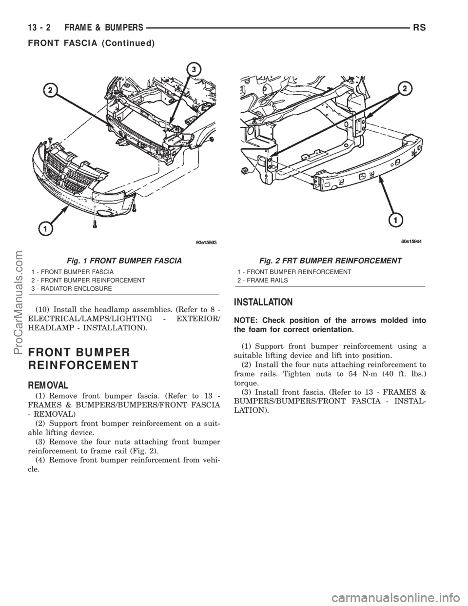
REMOVAL
(1) Remove front bumper fascia. (Refer to 13 -
FRAMES & BUMPERS/BUMPERS/FRONT FASCIA
- REMOVAL)
(2) Support front bumper reinforcement on a suit-
able lifting device.
(3) Remove the four nuts attaching front bumper
reinforcement to frame rail (Fig. 2).
(4) Remove front bumper reinforcement from vehi-
cle.
INSTALLATION
NOTE: Check position of the arrows molded into
the foam for correct orientation.
(1) Support front bumper reinforcement using a
suitable lifting device and lift into position.
(2) Install the four nuts attaching reinforcement to
frame rails. Tighten nuts to 54 N´m (40 ft. lbs.)
torque.
(3) Install front fascia. (Refer to 13 - FRAMES &
BUMPERS/BUMPERS/FRONT FASCIA - INSTAL-
LATION).
Fig. 1 FRONT BUMPER FASCIA
1 - FRONT BUMPER FASCIA
2 - FRONT BUMPER REINFORCEMENT
3 - RADIATOR ENCLOSURE
Fig. 2 FRT BUMPER REINFORCEMENT
1 - FRONT BUMPER REINFORCEMENT
2 - FRAME RAILS
13 - 2 FRAME & BUMPERSRS
FRONT FASCIA (Continued)
ProCarManuals.com
Page 1456 of 2399
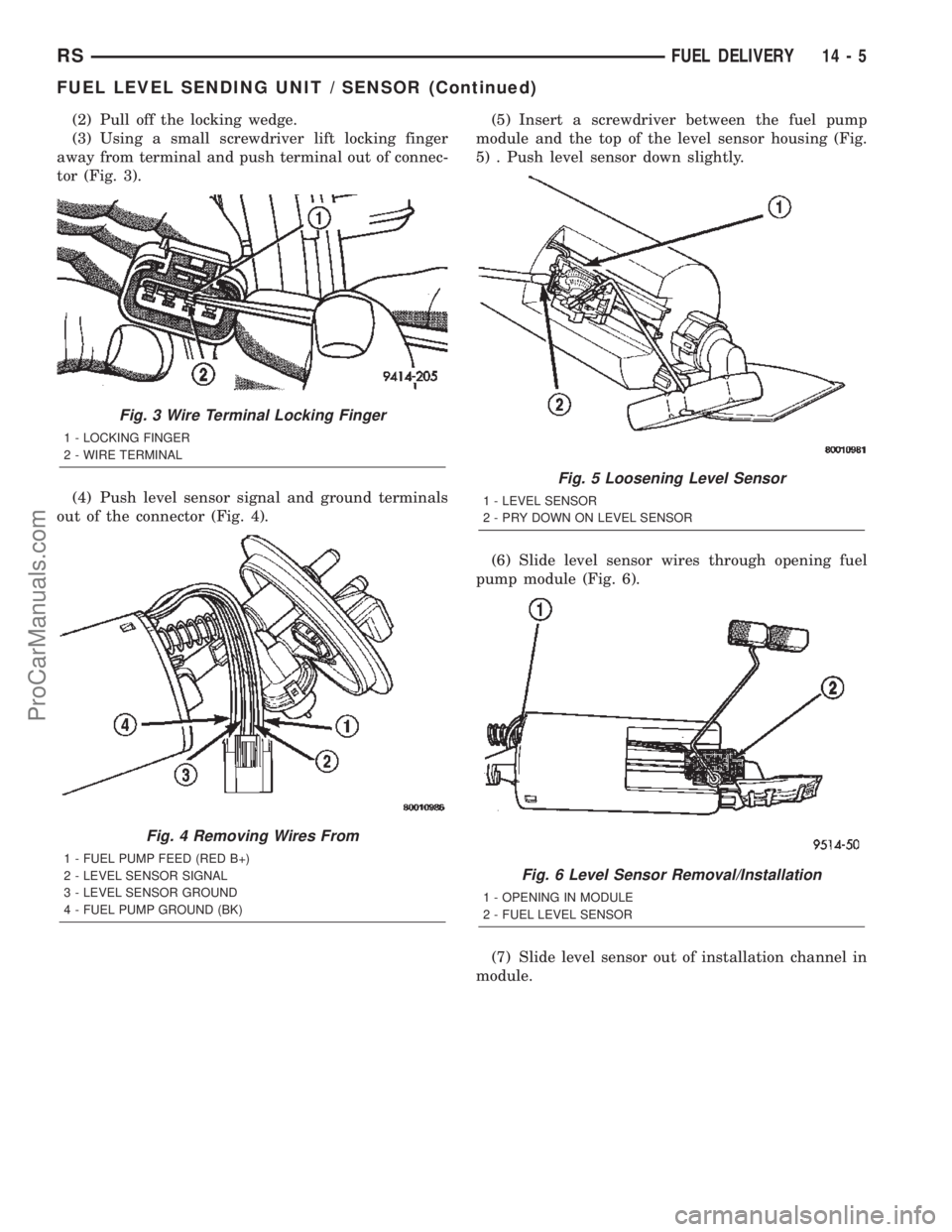
(2) Pull off the locking wedge.
(3) Using a small screwdriver lift locking finger
away from terminal and push terminal out of connec-
tor (Fig. 3).
(4) Push level sensor signal and ground terminals
out of the connector (Fig. 4).(5) Insert a screwdriver between the fuel pump
module and the top of the level sensor housing (Fig.
5) . Push level sensor down slightly.
(6) Slide level sensor wires through opening fuel
pump module (Fig. 6).
(7) Slide level sensor out of installation channel in
module.
Fig. 3 Wire Terminal Locking Finger
1 - LOCKING FINGER
2 - WIRE TERMINAL
Fig. 4 Removing Wires From
1 - FUEL PUMP FEED (RED B+)
2 - LEVEL SENSOR SIGNAL
3 - LEVEL SENSOR GROUND
4 - FUEL PUMP GROUND (BK)
Fig. 5 Loosening Level Sensor
1 - LEVEL SENSOR
2 - PRY DOWN ON LEVEL SENSOR
Fig. 6 Level Sensor Removal/Installation
1 - OPENING IN MODULE
2 - FUEL LEVEL SENSOR
RSFUEL DELIVERY14-5
FUEL LEVEL SENDING UNIT / SENSOR (Continued)
ProCarManuals.com
Page 1458 of 2399
leaks are not present. The component should be
replaced immediately if there is any evidence of deg-
radation that could result in failure.
Never attempt to repair a plastic fuel line/tube.
Replace as necessary.
Avoid contact of any fuel tubes/hoses with other
vehicle components that could cause abrasions or
scuffing. Be sure that the plastic fuel lines/tubes are
properly routed to prevent pinching and to avoid heat
sources.
FUEL PRESSURE REGULATOR
OPERATION
The fuel system uses a nonadjustable pressure reg-
ulator that maintains fuel system pressure at
approximately 400 34 kPa (58 5 psi). The fuel
pressure regulator contains a diaphragm, calibrated
spring and a fuel return valve. The spring pushes
down on the diaphragm and closes off the fuel return
port. System fuel pressure reflects the amount of fuel
pressure required to open the return port.
The pressure regulator is a mechanical device that
is NOT controlled by the PCM or engine vacuum.
REMOVAL
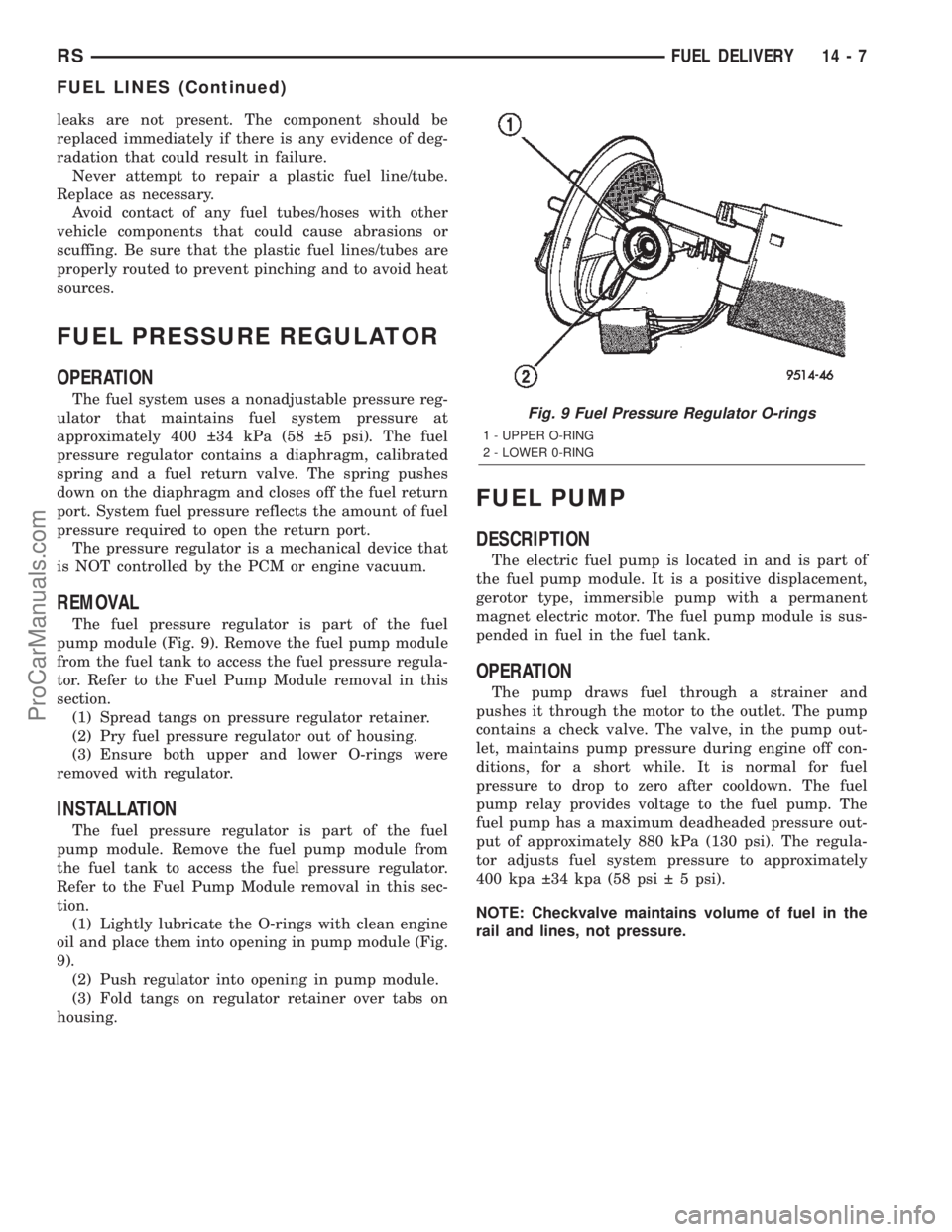
The fuel pressure regulator is part of the fuel
pump module (Fig. 9). Remove the fuel pump module
from the fuel tank to access the fuel pressure regula-
tor. Refer to the Fuel Pump Module removal in this
section.
(1) Spread tangs on pressure regulator retainer.
(2) Pry fuel pressure regulator out of housing.
(3) Ensure both upper and lower O-rings were
removed with regulator.
INSTALLATION
The fuel pressure regulator is part of the fuel
pump module. Remove the fuel pump module from
the fuel tank to access the fuel pressure regulator.
Refer to the Fuel Pump Module removal in this sec-
tion.
(1) Lightly lubricate the O-rings with clean engine
oil and place them into opening in pump module (Fig.
9).
(2) Push regulator into opening in pump module.
(3) Fold tangs on regulator retainer over tabs on
housing.
FUEL PUMP
DESCRIPTION
The electric fuel pump is located in and is part of
the fuel pump module. It is a positive displacement,
gerotor type, immersible pump with a permanent
magnet electric motor. The fuel pump module is sus-
pended in fuel in the fuel tank.
OPERATION
The pump draws fuel through a strainer and
pushes it through the motor to the outlet. The pump
contains a check valve. The valve, in the pump out-
let, maintains pump pressure during engine off con-
ditions, for a short while. It is normal for fuel
pressure to drop to zero after cooldown. The fuel
pump relay provides voltage to the fuel pump. The
fuel pump has a maximum deadheaded pressure out-
put of approximately 880 kPa (130 psi). The regula-
tor adjusts fuel system pressure to approximately
400 kpa 34 kpa (58 psi 5 psi).
NOTE: Checkvalve maintains volume of fuel in the
rail and lines, not pressure.
Fig. 9 Fuel Pressure Regulator O-rings
1 - UPPER O-RING
2 - LOWER 0-RING
RSFUEL DELIVERY14-7
FUEL LINES (Continued)
ProCarManuals.com
Page 1462 of 2399
REMOVAL
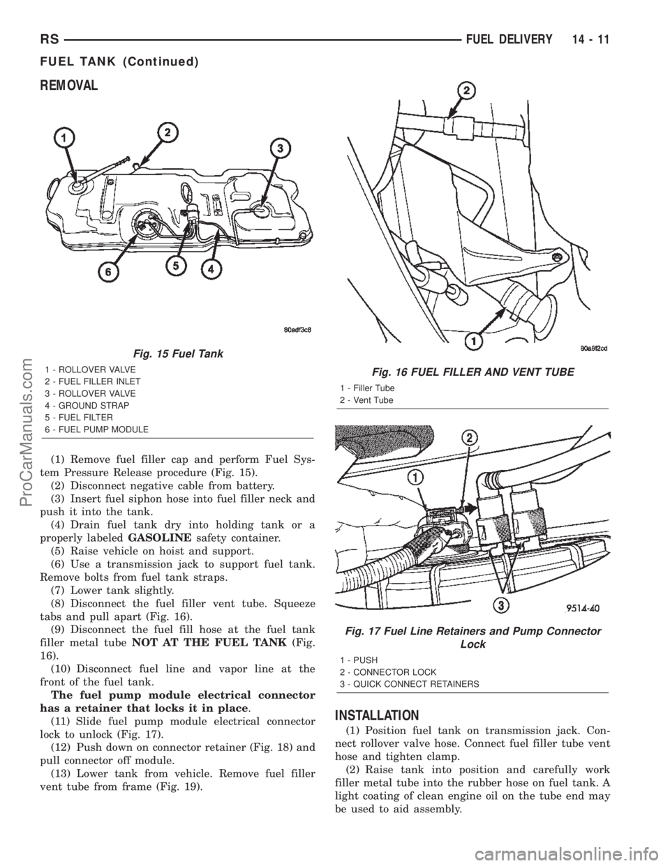
(1) Remove fuel filler cap and perform Fuel Sys-
tem Pressure Release procedure (Fig. 15).
(2) Disconnect negative cable from battery.
(3) Insert fuel siphon hose into fuel filler neck and
push it into the tank.
(4) Drain fuel tank dry into holding tank or a
properly labeledGASOLINEsafety container.
(5) Raise vehicle on hoist and support.
(6) Use a transmission jack to support fuel tank.
Remove bolts from fuel tank straps.
(7) Lower tank slightly.
(8) Disconnect the fuel filler vent tube. Squeeze
tabs and pull apart (Fig. 16).
(9) Disconnect the fuel fill hose at the fuel tank
filler metal tubeNOT AT THE FUEL TANK(Fig.
16).
(10) Disconnect fuel line and vapor line at the
front of the fuel tank.
The fuel pump module electrical connector
has a retainer that locks it in place.
(11) Slide fuel pump module electrical connector
lock to unlock (Fig. 17).
(12) Push down on connector retainer (Fig. 18) and
pull connector off module.
(13) Lower tank from vehicle. Remove fuel filler
vent tube from frame (Fig. 19).
INSTALLATION
(1) Position fuel tank on transmission jack. Con-
nect rollover valve hose. Connect fuel filler tube vent
hose and tighten clamp.
(2) Raise tank into position and carefully work
filler metal tube into the rubber hose on fuel tank. A
light coating of clean engine oil on the tube end may
be used to aid assembly.
Fig. 15 Fuel Tank
1 - ROLLOVER VALVE
2 - FUEL FILLER INLET
3 - ROLLOVER VALVE
4 - GROUND STRAP
5 - FUEL FILTER
6 - FUEL PUMP MODULEFig. 16 FUEL FILLER AND VENT TUBE
1 - Filler Tube
2 - Vent Tube
Fig. 17 Fuel Line Retainers and Pump Connector
Lock
1 - PUSH
2 - CONNECTOR LOCK
3 - QUICK CONNECT RETAINERS
RSFUEL DELIVERY14-11
FUEL TANK (Continued)
ProCarManuals.com
Page 1469 of 2399
1 second. Therefore, battery voltage is not supplied to
the fuel pump, ignition coil, fuel injectors and heated
oxygen sensors.
ENGINE START-UP MODE
This is an OPEN LOOP mode. If the vehicle is in
park or neutral (automatic transaxles) or the clutch
pedal is depressed (manual transaxles) the ignition
switch energizes the starter relay. The following
actions occur when the starter motor is engaged.
²If the PCM receives the camshaft position sensor
and crankshaft position sensor signals, it energizes
the Auto Shutdown (ASD) relay and fuel pump relay.
If the PCM does not receive both signals within
approximately one second, it will not energize the
ASD relay and fuel pump relay. The ASD and fuel
pump relays supply battery voltage to the fuel pump,
fuel injectors, ignition coil, (EGR solenoid and PCV
heater if equipped) and heated oxygen sensors.
²The PCM energizes the injectors (on the 69É
degree falling edge) for a calculated pulse width until
it determines crankshaft position from the camshaft
position sensor and crankshaft position sensor sig-
nals. The PCM determines crankshaft position within
1 engine revolution.
²After determining crankshaft position, the PCM
begins energizing the injectors in sequence. It adjusts
injector pulse width and controls injector synchroni-
zation by turning the individual ground paths to the
injectors On and Off.
²When the engine idles within 64 RPM of its
target RPM, the PCM compares current MAP sensor
value with the atmospheric pressure value received
during the Ignition Switch On (zero RPM) mode.
Once the ASD and fuel pump relays have been
energized, the PCM determines injector pulse width
based on the following:
²MAP
²Engine RPM
²Battery voltage
²Engine coolant temperature
²Inlet/Intake air temperature (IAT)
²Throttle position
²The number of engine revolutions since cranking
was initiated
During Start-up the PCM maintains ignition tim-
ing at 9É BTDC.
ENGINE WARM-UP MODE
This is an OPEN LOOP mode. The following inputs
are received by the PCM:
²Manifold Absolute Pressure (MAP)
²Crankshaft position (engine speed)
²Engine coolant temperature
²Inlet/Intake air temperature (IAT)
²Camshaft position²Knock sensor
²Throttle position
²A/C switch
²Battery voltage
²Vehicle speed
²Speed control
²O2 sensors
The PCM adjusts injector pulse width and controls
injector synchronization by turning the individual
ground paths to the injectors On and Off.
The PCM adjusts ignition timing and engine idle
speed. Engine idle speed is adjusted through the idle
air control motor.
CRUISE OR IDLE MODE
When the engine is at operating temperature this
is a CLOSED LOOP mode. During cruising or idle
the following inputs are received by the PCM:
²Manifold absolute pressure
²Crankshaft position (engine speed)
²Inlet/Intake air temperature
²Engine coolant temperature
²Camshaft position
²Knock sensor
²Throttle position
²Exhaust gas oxygen content
²A/C control positions
²Battery voltage
²Vehicle speed
The PCM adjusts injector pulse width and controls
injector synchronization by turning the individual
ground paths to the injectors On and Off.
The PCM adjusts engine idle speed and ignition
timing. The PCM adjusts the air/fuel ratio according
to the oxygen content in the exhaust gas (measured
by the upstream and downstream heated oxygen sen-
sor).
The PCM monitors for engine misfire. During
active misfire and depending on the severity, the
PCM either continuously illuminates or flashes the
malfunction indicator lamp (Check Engine light on
instrument panel). Also, the PCM stores an engine
misfire DTC in memory, if 2nd trip with fault.
The PCM performs several diagnostic routines.
They include:
²Oxygen sensor monitor
²Downstream heated oxygen sensor diagnostics
during open loop operation (except for shorted)
²Fuel system monitor
²EGR monitor (if equipped)
²Purge system monitor
²Catalyst efficiency monitor
²All inputs monitored for proper voltage range,
rationality.
²All monitored components (refer to the Emission
section for On-Board Diagnostics).
14 - 18 FUEL INJECTIONRS
FUEL INJECTION (Continued)
ProCarManuals.com
Page 1478 of 2399
FUEL PUMP RELAY
DESCRIPTION
The fuel pump relay is located in the PDC. The
inside top of the PDC cover has a label showing relay
and fuse location.
OPERATION
The fuel pump relay supplies battery voltage to the
fuel pump. A buss bar in the Power Distribution Cen-
ter (PDC) supplies voltage to the solenoid side and
contact side of the relay. The fuel pump relay power
circuit contains a fuse between the buss bar in the
PDC and the relay. The fuse is located in the PDC.
Refer to the Wiring Diagrams for circuit information.
The PCM controls the fuel pump relay by switch-
ing the ground path for the solenoid side of the relay
on and off. The PCM turns the ground path off when
the ignition switch is in the Off position. When the
ignition switch is in the On position, the PCM ener-
gizes the fuel pump. If the crankshaft position sensor
does not detect engine rotation, the PCM de-ener-
gizes the relay after approximately one second.
IDLE AIR CONTROL MOTOR
DESCRIPTION
The idle air control motor is mounted on the throt-
tle body. The PCM operates the idle air control motor
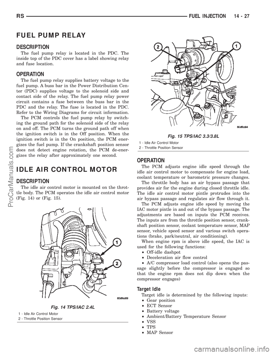
(Fig. 14) or (Fig. 15).
OPERATION
The PCM adjusts engine idle speed through the
idle air control motor to compensate for engine load,
coolant temperature or barometric pressure changes.
The throttle body has an air bypass passage that
provides air for the engine during closed throttle idle.
The idle air control motor pintle protrudes into the
air bypass passage and regulates air flow through it.
The PCM adjusts engine idle speed by moving the
IAC motor pintle in and out of the bypass passage. The
adjustments are based on inputs the PCM receives.
The inputs are from the throttle position sensor, crank-
shaft position sensor, coolant temperature sensor, MAP
sensor, vehicle speed sensor and various switch opera-
tions (brake, park/neutral, air conditioning).
When engine rpm is above idle speed, the IAC is
used for the following functions:
²Off-idle dashpot
²Deceleration air flow control
²A/C compressor load control (also opens the pas-
sage slightly before the compressor is engaged so
that the engine rpm does not dip down when the
compressor engages)
Target Idle
Target idle is determined by the following inputs:
²Gear position
²ECT Sensor
²Battery voltage
²Ambient/Battery Temperature Sensor
²VSS
²TPS
²MAP Sensor
Fig. 14 TPS/IAC 2.4L
1 - Idle Air Control Motor
2 - Throttle Position Sensor
Fig. 15 TPS/IAC 3.3/3.8L
1 - Idle Air Control Motor
2 - Throttle Position Sensor
RSFUEL INJECTION14-27
ProCarManuals.com
Page 1479 of 2399
REMOVAL
When servicing throttle body components, always
reassemble components with new O-rings and seals
where applicable. Never use lubricants on O-rings or
seals, damage may result. If assembly of component
is difficult, use water to aid assembly. Use care when
removing hoses to prevent damage to hose or hose
nipple.
(1) Disconnect negative cable from battery.
(2) Remove electrical connector from idle air con-
trol motor.
(3) Remove idle air control motor mounting screws.
(4) Remove motor from throttle body. Ensure the
O-rings is removed with the motor.
INSTALLATION
When servicing throttle body components, always
reassemble components with new O-rings and seals
where applicable. Never use lubricants on O-rings or
seals, damage may result. If assembly of component
is difficult,a light coat of engine oil may be
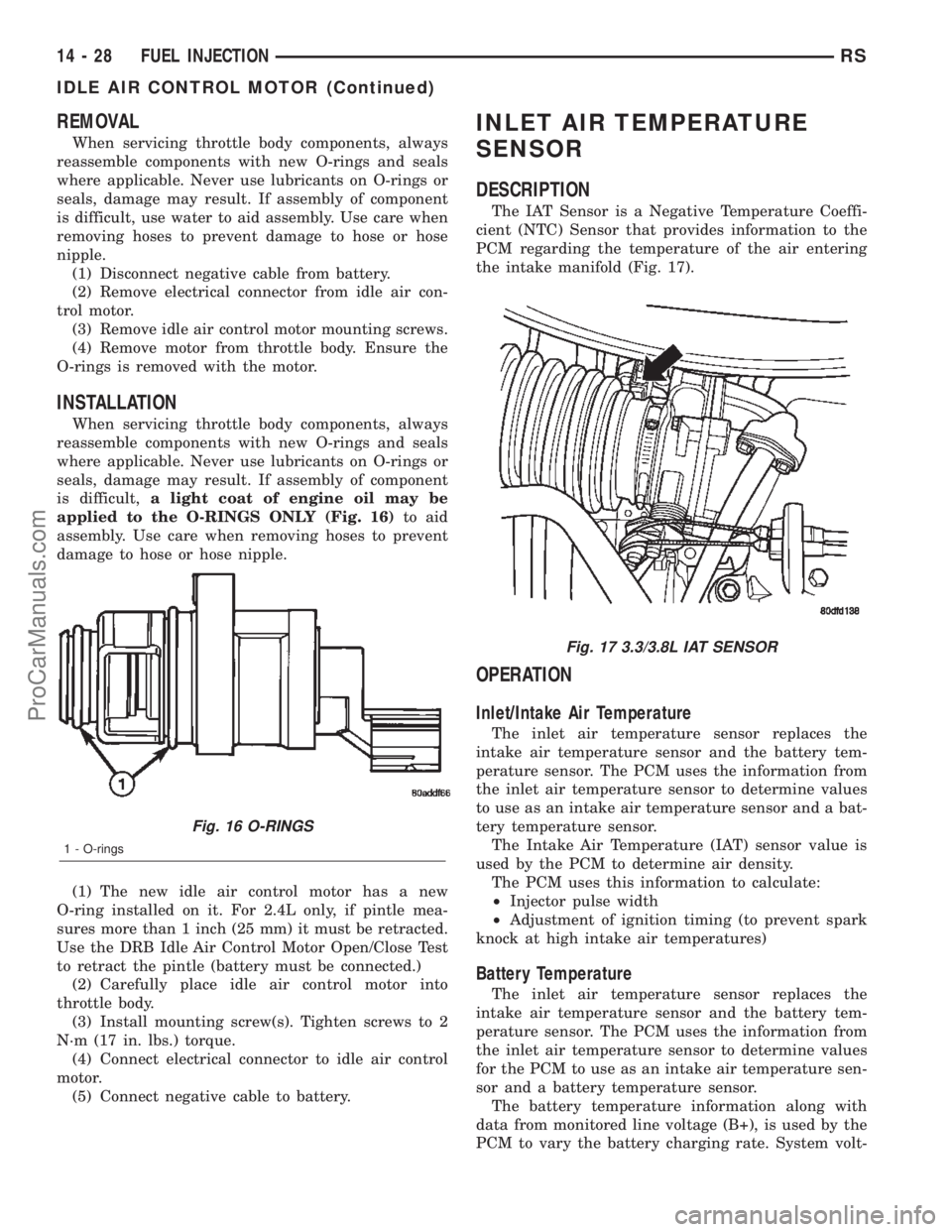
applied to the O-RINGS ONLY (Fig. 16)to aid
assembly. Use care when removing hoses to prevent
damage to hose or hose nipple.
(1) The new idle air control motor has a new
O-ring installed on it. For 2.4L only, if pintle mea-
sures more than 1 inch (25 mm) it must be retracted.
Use the DRB Idle Air Control Motor Open/Close Test
to retract the pintle (battery must be connected.)
(2) Carefully place idle air control motor into
throttle body.
(3) Install mounting screw(s). Tighten screws to 2
N´m (17 in. lbs.) torque.
(4) Connect electrical connector to idle air control
motor.
(5) Connect negative cable to battery.
INLET AIR TEMPERATURE
SENSOR
DESCRIPTION
The IAT Sensor is a Negative Temperature Coeffi-
cient (NTC) Sensor that provides information to the
PCM regarding the temperature of the air entering
the intake manifold (Fig. 17).
OPERATION
Inlet/Intake Air Temperature
The inlet air temperature sensor replaces the
intake air temperature sensor and the battery tem-
perature sensor. The PCM uses the information from
the inlet air temperature sensor to determine values
to use as an intake air temperature sensor and a bat-
tery temperature sensor.
The Intake Air Temperature (IAT) sensor value is
used by the PCM to determine air density.
The PCM uses this information to calculate:
²Injector pulse width
²Adjustment of ignition timing (to prevent spark
knock at high intake air temperatures)
Battery Temperature
The inlet air temperature sensor replaces the
intake air temperature sensor and the battery tem-
perature sensor. The PCM uses the information from
the inlet air temperature sensor to determine values
for the PCM to use as an intake air temperature sen-
sor and a battery temperature sensor.
The battery temperature information along with
data from monitored line voltage (B+), is used by the
PCM to vary the battery charging rate. System volt-
Fig. 16 O-RINGS
1 - O-rings
Fig. 17 3.3/3.8L IAT SENSOR
14 - 28 FUEL INJECTIONRS
IDLE AIR CONTROL MOTOR (Continued)
ProCarManuals.com
Page 1483 of 2399
stream sensor begins to match the upstream sensor
input except for a slight time delay. By comparing
the downstream heated oxygen sensor input to the
input from the upstream sensor, the PCM calculates
catalytic convertor efficiency. Also used to establish
the upstream O2 goal voltage (switching point).
REMOVAL
REMOVAL - UPSTREAM 1/1 - 2.4L
(1) Disconnect the negative battery cable.
(2) Raise and support the vehicle.
(3) Disconnect the electrical connector (Fig. 21).
(4) Use a socket such as the Snap-OntYA8875 or
equivalent to remove the sensor
(5) When the sensor is removed, the threads must
be cleaned with an 18 mm X 1.5 + 6E tap. If using
the original sensor, coat the threads with Loctite
771±64 anti-seize compound or equivalent.
REMOVAL - UPSTREAM 1/1 - 3.3/3.8L
(1) Remove battery, refer to the Battery section for
more information.
(2) Remove the battery tray, refer to the Battery
section for more information.
(3) Disconnect the speed control vacuum harness
from servo.
(4) Disconnect the electrical connector from servo.
(5) Remove the speed control servo and bracket
and reposition.
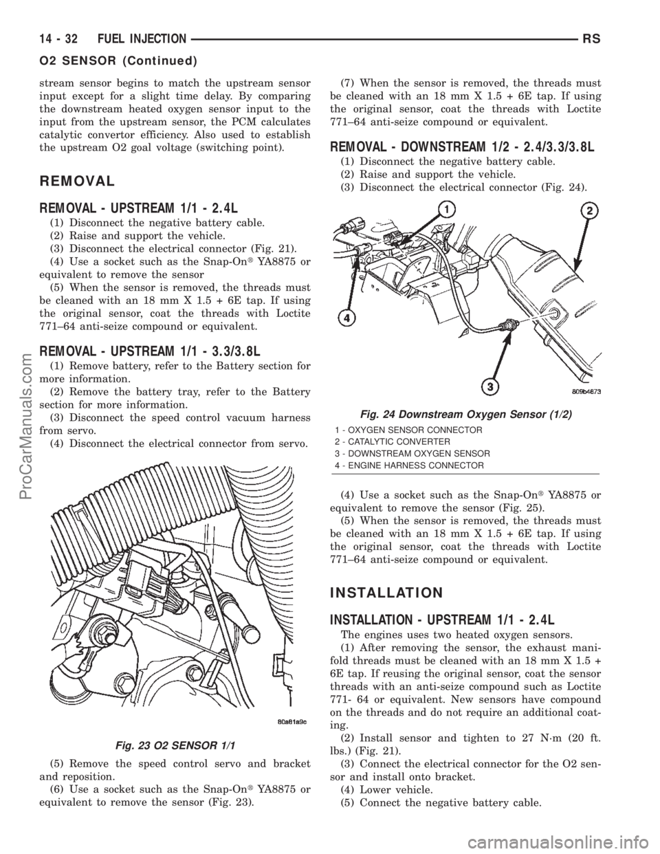
(6) Use a socket such as the Snap-OntYA8875 or
equivalent to remove the sensor (Fig. 23).(7) When the sensor is removed, the threads must
be cleaned with an 18 mm X 1.5 + 6E tap. If using
the original sensor, coat the threads with Loctite
771±64 anti-seize compound or equivalent.
REMOVAL - DOWNSTREAM 1/2 - 2.4/3.3/3.8L
(1) Disconnect the negative battery cable.
(2) Raise and support the vehicle.
(3) Disconnect the electrical connector (Fig. 24).
(4) Use a socket such as the Snap-OntYA8875 or
equivalent to remove the sensor (Fig. 25).
(5) When the sensor is removed, the threads must
be cleaned with an 18 mm X 1.5 + 6E tap. If using
the original sensor, coat the threads with Loctite
771±64 anti-seize compound or equivalent.
INSTALLATION
INSTALLATION - UPSTREAM 1/1 - 2.4L
The engines uses two heated oxygen sensors.
(1) After removing the sensor, the exhaust mani-
fold threads must be cleaned with an 18 mm X 1.5 +
6E tap. If reusing the original sensor, coat the sensor
threads with an anti-seize compound such as Loctite
771- 64 or equivalent. New sensors have compound
on the threads and do not require an additional coat-
ing.
(2) Install sensor and tighten to 27 N´m (20 ft.
lbs.) (Fig. 21).
(3) Connect the electrical connector for the O2 sen-
sor and install onto bracket.
(4) Lower vehicle.
(5) Connect the negative battery cable.
Fig. 23 O2 SENSOR 1/1
Fig. 24 Downstream Oxygen Sensor (1/2)
1 - OXYGEN SENSOR CONNECTOR
2 - CATALYTIC CONVERTER
3 - DOWNSTREAM OXYGEN SENSOR
4 - ENGINE HARNESS CONNECTOR
14 - 32 FUEL INJECTIONRS
O2 SENSOR (Continued)
ProCarManuals.com