2002 CHRYSLER CARAVAN warning
[x] Cancel search: warningPage 1549 of 2399
(3) Raise vehicle. (Refer to LUBRICATION &
MAINTENANCE/HOISTING - STANDARD PROCE-
DURE)
(4) Remove front emissions vapor canister. (Refer
to 25 - EMISSIONS CONTROL/EVAPORATIVE
EMISSIONS/VAPOR CANISTER - REMOVAL)
(5) Place an oil drain pan under vehicle to catch
power steering fluid.
(6) Back out pressure hose tube nut at power
steering pump pressure fitting and remove hose from
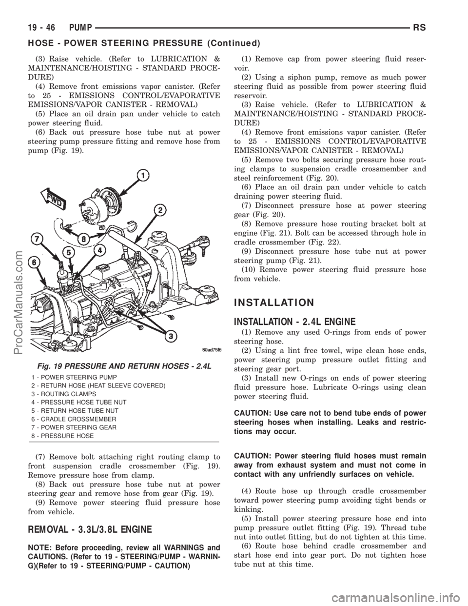
pump (Fig. 19).
(7) Remove bolt attaching right routing clamp to
front suspension cradle crossmember (Fig. 19).
Remove pressure hose from clamp.
(8) Back out pressure hose tube nut at power
steering gear and remove hose from gear (Fig. 19).
(9) Remove power steering fluid pressure hose
from vehicle.
REMOVAL - 3.3L/3.8L ENGINE
NOTE:Before proceeding, review all WARNINGS and
CAUTIONS. (Refer to 19 - STEERING/PUMP - WARNIN-
G)(Refer to 19 - STEERING/PUMP - CAUTION)
(1) Remove cap from power steering fluid reser-
voir.
(2) Using a siphon pump, remove as much power
steering fluid as possible from power steering fluid
reservoir.
(3) Raise vehicle. (Refer to LUBRICATION &
MAINTENANCE/HOISTING - STANDARD PROCE-
DURE)
(4) Remove front emissions vapor canister. (Refer
to 25 - EMISSIONS CONTROL/EVAPORATIVE
EMISSIONS/VAPOR CANISTER - REMOVAL)
(5) Remove two bolts securing pressure hose rout-
ing clamps to suspension cradle crossmember and
steel reinforcement (Fig. 20).
(6) Place an oil drain pan under vehicle to catch
draining power steering fluid.
(7) Disconnect pressure hose at power steering
gear (Fig. 20).
(8) Remove pressure hose routing bracket bolt at
engine (Fig. 21). Bolt can be accessed through hole in
cradle crossmember (Fig. 22).
(9) Disconnect pressure hose tube nut at power
steering pump (Fig. 21).
(10) Remove power steering fluid pressure hose
from vehicle.
INSTALLATION
INSTALLATION - 2.4L ENGINE
(1) Remove any used O-rings from ends of power
steering hose.
(2) Using a lint free towel, wipe clean hose ends,
power steering pump pressure outlet fitting and
steering gear port.
(3) Install new O-rings on ends of power steering
fluid pressure hose. Lubricate O-rings using clean
power steering fluid.
CAUTION: Use care not to bend tube ends of power
steering hoses when installing. Leaks and restric-
tions may occur.
CAUTION: Power steering fluid hoses must remain
away from exhaust system and must not come in
contact with any unfriendly surfaces on vehicle.
(4) Route hose up through cradle crossmember
toward power steering pump avoiding tight bends or
kinking.
(5) Install power steering pressure hose end into
pump pressure outlet fitting (Fig. 19). Thread tube
nut into outlet fitting, but do not tighten at this time.
(6) Route hose behind cradle crossmember and
start hose end into gear port. Do not tighten hose
tube nut at this time.
Fig. 19 PRESSURE AND RETURN HOSES - 2.4L
1 - POWER STEERING PUMP
2 - RETURN HOSE (HEAT SLEEVE COVERED)
3 - ROUTING CLAMPS
4 - PRESSURE HOSE TUBE NUT
5 - RETURN HOSE TUBE NUT
6 - CRADLE CROSSMEMBER
7 - POWER STEERING GEAR
8 - PRESSURE HOSE
19 - 46 PUMPRS
HOSE - POWER STEERING PRESSURE (Continued)
ProCarManuals.com
Page 1552 of 2399
(10) Tighten hose tube nut at power steering gear
port to 31 N´m (275 in. lbs.) torque.
(11) Install front emissions vapor canister. (Refer
to 25 - EMISSIONS CONTROL/EVAPORATIVE
EMISSIONS/VAPOR CANISTER - INSTALLATION)
(12) Lower vehicle.
(13) Fill and bleed the power steering system
using the Power Steering Pump Initial Operation
Procedure. (Refer to 19 - STEERING/PUMP - STAN-
DARD PROCEDURE)
(14) Inspect system for leaks.
HOSE - POWER STEERING
RETURN
REMOVAL
REMOVAL - 2.4L ENGINE
NOTE: Before proceeding, review all WARNINGS
and CAUTIONS. (Refer to 19 - STEERING/PUMP -
WARNING)(Refer to 19 - STEERING/PUMP - CAU-
TION)
(1) Remove cap from power steering fluid reser-
voir.
(2) Using a siphon pump, remove as much power
steering fluid as possible from power steering fluid
reservoir.
(3) Raise vehicle. (Refer to LUBRICATION &
MAINTENANCE/HOISTING - STANDARD PROCE-
DURE)
(4) Remove front emissions vapor canister. (Refer
to 25 - EMISSIONS CONTROL/EVAPORATIVE
EMISSIONS/VAPOR CANISTER - REMOVAL)
(5) Place an oil drain pan under vehicle to catch
power steering fluid.
(6) Cut tie-strap securing insulating heat sleeve to
power steering fluid return hose near power steering
pump. Pull back heat sleeve to expose hose clamp.
(7) Remove clamp, then return hose from power
steering pump (Fig. 19).
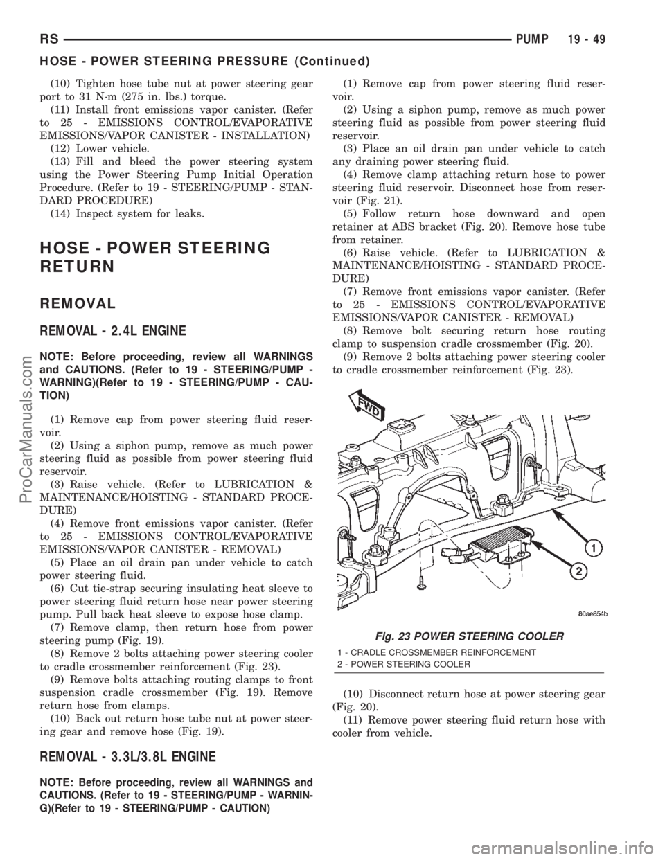
(8) Remove 2 bolts attaching power steering cooler
to cradle crossmember reinforcement (Fig. 23).
(9) Remove bolts attaching routing clamps to front
suspension cradle crossmember (Fig. 19). Remove
return hose from clamps.
(10) Back out return hose tube nut at power steer-
ing gear and remove hose (Fig. 19).
REMOVAL - 3.3L/3.8L ENGINE
NOTE:Before proceeding, review all WARNINGS and
CAUTIONS. (Refer to 19 - STEERING/PUMP - WARNIN-
G)(Refer to 19 - STEERING/PUMP - CAUTION)
(1) Remove cap from power steering fluid reser-
voir.
(2) Using a siphon pump, remove as much power
steering fluid as possible from power steering fluid
reservoir.
(3) Place an oil drain pan under vehicle to catch
any draining power steering fluid.
(4) Remove clamp attaching return hose to power
steering fluid reservoir. Disconnect hose from reser-
voir (Fig. 21).
(5) Follow return hose downward and open
retainer at ABS bracket (Fig. 20). Remove hose tube
from retainer.
(6) Raise vehicle. (Refer to LUBRICATION &
MAINTENANCE/HOISTING - STANDARD PROCE-
DURE)
(7) Remove front emissions vapor canister. (Refer
to 25 - EMISSIONS CONTROL/EVAPORATIVE
EMISSIONS/VAPOR CANISTER - REMOVAL)
(8) Remove bolt securing return hose routing
clamp to suspension cradle crossmember (Fig. 20).
(9) Remove 2 bolts attaching power steering cooler
to cradle crossmember reinforcement (Fig. 23).
(10) Disconnect return hose at power steering gear
(Fig. 20).
(11) Remove power steering fluid return hose with
cooler from vehicle.
Fig. 23 POWER STEERING COOLER
1 - CRADLE CROSSMEMBER REINFORCEMENT
2 - POWER STEERING COOLER
RSPUMP19-49
HOSE - POWER STEERING PRESSURE (Continued)
ProCarManuals.com
Page 1554 of 2399
HOSE - POWER STEERING
SUPPLY
REMOVAL
REMOVAL - 2.4L ENGINE
(1) Remove filler cap from power steering fluid res-
ervoir.
(2) Using a siphon pump, remove as much power
steering fluid as possible from the power steering
fluid reservoir.
(3) Raise vehicle. (Refer to LUBRICATION &
MAINTENANCE/HOISTING - STANDARD PROCE-
DURE)
(4) Remove hose clamp securing supply hose to
power steering pump, then remove supply hose from
pump fitting.
(5) Lower vehicle.
(6) Remove hose clamp attaching power steering
fluid supply hose to power steering fluid reservoir,
then remove supply hose.
(7) Remove the power steering fluid supply hose
from the vehicle.
REMOVAL - 3.3L/3.8L ENGINE
NOTE: Before proceeding, review all WARNINGS
and CAUTIONS. (Refer to 19 - STEERING/PUMP -
WARNING)(Refer to 19 - STEERING/PUMP - CAU-
TION)
(1) Remove cap from power steering fluid reser-
voir.
(2) Using a siphon pump, remove as much power
steering fluid as possible from power steering fluid
reservoir.
(3) Place an oil drain pan under vehicle to catch
any draining power steering fluid.
(4) Remove clamp attaching supply hose to power
steering fluid reservoir. Disconnect hose from reser-
voir (Fig. 21).
(5) Pull upward on hose routing clip releasing it
from bracket on cylinder head cover (Fig. 21).
NOTE: It may be necessary to remove air cleaner
housing to gain greater access to supply hose at
power steering pump. (Refer to 9 - ENGINE/AIR
INTAKE SYSTEM/AIR CLEANER HOUSING -
REMOVAL)
(6) Remove clamp attaching supply hose to power
steering pump. Disconnect hose from pump and
remove from vehicle (Fig. 21).
INSTALLATION
INSTALLATION - 2.4L ENGINE
(1) Install and correctly route power steering fluid
supply hose from remote fluid reservoir to power
steering pump.
(2) Install fluid supply hose onto power steering
fluid reservoir. Install hose clamp.Be sure hose
clamp is installed past bead on fluid reservoir
fitting.
(3) Raise vehicle. (Refer to LUBRICATION &
MAINTENANCE/HOISTING - STANDARD PROCE-
DURE)
(4) Install power steering fluid supply hose on
power steering pump supply fitting. Install hose
clamp.Be sure hose clamp is installed past bead
on pump fitting.
(5) Lower vehicle.
(6) Fill and bleed power steering system using
Power Steering Pump Initial Operation Procedure.
(Refer to 19 - STEERING/PUMP - STANDARD PRO-
CEDURE)
(7) Inspect system for leaks.
INSTALLATION - 3.3L/3.8L ENGINE
(1) Install supply hose onto supply fitting on power
steering pump (Fig. 21). Slide the hose clamp into
position on fluid reservoir and attach it.Be sure
hose clamp in installed past bead on fluid res-
ervoir fitting.
(2) Align routing clip located toward center of sup-
ply hose with hole in bracket on cylinder head cover
and push into place (Fig. 21).
(3) Install supply hose onto reservoir (Fig. 21).
Slide the hose clamp into position on fluid reservoir
and attach it.Be sure hose clamp in installed
past bead on fluid reservoir fitting.
(4) Fill and bleed power steering system using
Power Steering Pump Initial Operation Procedure.
(Refer to 19 - STEERING/PUMP - STANDARD PRO-
CEDURE)
(5) Inspect system for leaks.
RESERVOIR - POWER
STEERING FLUID
DESCRIPTION
DESCRIPTION - 2.4L/3.3L/3.8L ENGINE
All vehicles use a remote mounted power steering
fluid reservoir. The power steering fluid reservoir is
mounted to the engine near the battery (Fig. 24).
RSPUMP19-51
ProCarManuals.com
Page 1649 of 2399
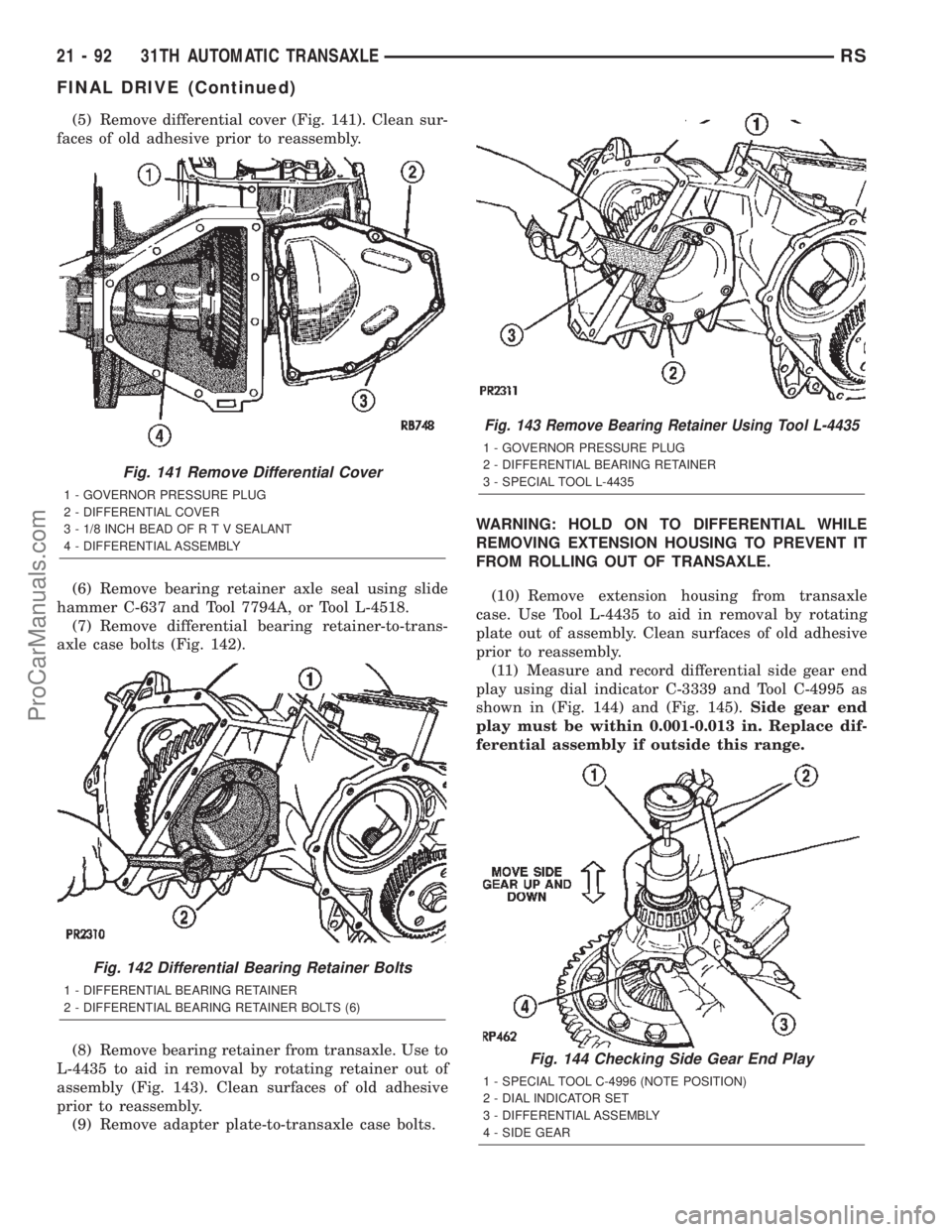
(5) Remove differential cover (Fig. 141). Clean sur-
faces of old adhesive prior to reassembly.
(6) Remove bearing retainer axle seal using slide
hammer C-637 and Tool 7794A, or Tool L-4518.
(7) Remove differential bearing retainer-to-trans-
axle case bolts (Fig. 142).
(8) Remove bearing retainer from transaxle. Use to
L-4435 to aid in removal by rotating retainer out of
assembly (Fig. 143). Clean surfaces of old adhesive
prior to reassembly.
(9) Remove adapter plate-to-transaxle case bolts.WARNING: HOLD ON TO DIFFERENTIAL WHILE
REMOVING EXTENSION HOUSING TO PREVENT IT
FROM ROLLING OUT OF TRANSAXLE.
(10) Remove extension housing from transaxle
case. Use Tool L-4435 to aid in removal by rotating
plate out of assembly. Clean surfaces of old adhesive
prior to reassembly.
(11) Measure and record differential side gear end
play using dial indicator C-3339 and Tool C-4995 as
shown in (Fig. 144) and (Fig. 145).Side gear end
play must be within 0.001-0.013 in. Replace dif-
ferential assembly if outside this range.
Fig. 141 Remove Differential Cover
1 - GOVERNOR PRESSURE PLUG
2 - DIFFERENTIAL COVER
3 - 1/8 INCH BEAD OF R T V SEALANT
4 - DIFFERENTIAL ASSEMBLY
Fig. 142 Differential Bearing Retainer Bolts
1 - DIFFERENTIAL BEARING RETAINER
2 - DIFFERENTIAL BEARING RETAINER BOLTS (6)
Fig. 143 Remove Bearing Retainer Using Tool L-4435
1 - GOVERNOR PRESSURE PLUG
2 - DIFFERENTIAL BEARING RETAINER
3 - SPECIAL TOOL L-4435
Fig. 144 Checking Side Gear End Play
1 - SPECIAL TOOL C-4996 (NOTE POSITION)
2 - DIAL INDICATOR SET
3 - DIFFERENTIAL ASSEMBLY
4 - SIDE GEAR
21 - 92 31TH AUTOMATIC TRANSAXLERS
FINAL DRIVE (Continued)
ProCarManuals.com
Page 1795 of 2399
OPERATION
The three input clutches are responsible for driving
different components of the planetary geartrain.
NOTE: Refer to the ªElements In Useº chart in Diag-
nosis and Testing for a collective view of which
clutch elements are applied at each position of the
selector lever.
UNDERDRIVE CLUTCH
The underdrive clutch is hydraulically applied in
first, second, and third (direct) gears by pressurized
fluid against the underdrive piston. When the under-
drive clutch is applied, the underdrive hub drives the
rear sun gear.
OVERDRIVE CLUTCH
The overdrive clutch is hydraulically applied in
third (direct) and overdrive gears by pressurized fluid
against the overdrive/reverse piston. When the over-
drive clutch is applied, the overdrive hub drives the
front planet carrier.
REVERSE CLUTCH
The reverse clutch is hydraulically applied in
reverse gear only by pressurized fluid against the
overdrive/reverse piston. When the reverse clutch is
applied, the front sun gear assembly is driven.
FINAL DRIVE
DISASSEMBLY
NOTE: The differential is serviced as an assembly.
Differential service is limited to bearing cups and
cones. Any other differential component failure
must be remedied by differential assembly and
transfer shaft replacement.
The transfer shaft should be removed for differen-
tial repair and bearing turning torque checking.
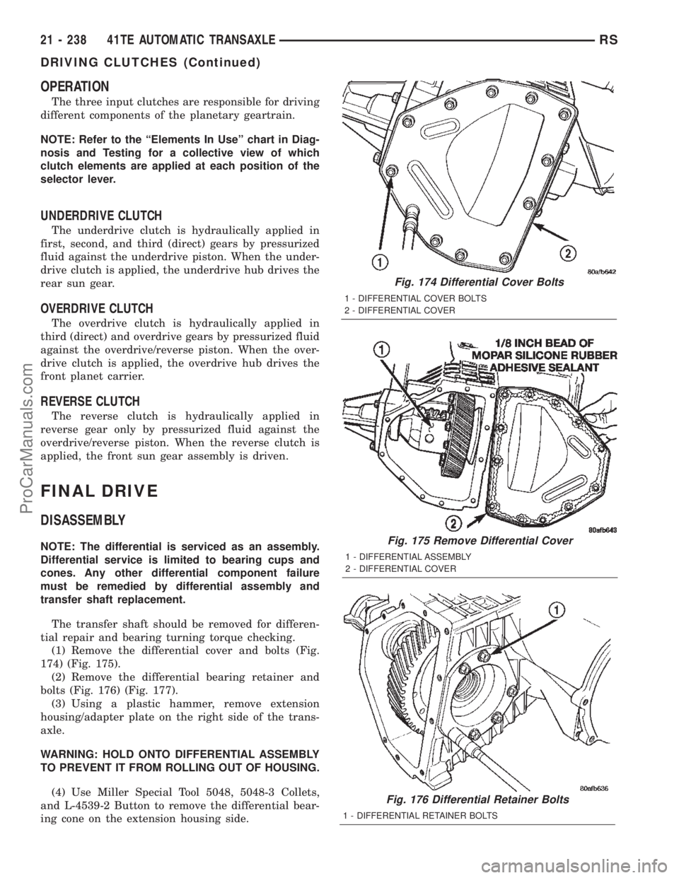
(1) Remove the differential cover and bolts (Fig.
174) (Fig. 175).
(2) Remove the differential bearing retainer and
bolts (Fig. 176) (Fig. 177).
(3) Using a plastic hammer, remove extension
housing/adapter plate on the right side of the trans-
axle.
WARNING: HOLD ONTO DIFFERENTIAL ASSEMBLY
TO PREVENT IT FROM ROLLING OUT OF HOUSING.
(4) Use Miller Special Tool 5048, 5048-3 Collets,
and L-4539-2 Button to remove the differential bear-
ing cone on the extension housing side.
Fig. 174 Differential Cover Bolts
1 - DIFFERENTIAL COVER BOLTS
2 - DIFFERENTIAL COVER
Fig. 175 Remove Differential Cover
1 - DIFFERENTIAL ASSEMBLY
2 - DIFFERENTIAL COVER
Fig. 176 Differential Retainer Bolts
1 - DIFFERENTIAL RETAINER BOLTS
21 - 238 41TE AUTOMATIC TRANSAXLERS
DRIVING CLUTCHES (Continued)
ProCarManuals.com
Page 1971 of 2399
SENSOR - TPM
DESCRIPTION
On vehicles equipped with Tire Pressure Monitor-
ing, one tire pressure sensor is mounted to each
wheel (Fig. 19). Each sensor has an internal battery
that lasts up to 10 years. The battery is not service-
able. At the time of battery failure, the sensor must
be replaced. The serviceable components of the tire
pressure sensor are:
²Sensor-To-Wheel Grommet
²Valve Stem Cap
²Valve Stem Core
Valve stem caps and cores are specifically designed
for the tire pressure monitoring sensors. Although
similar to standard valve stem caps and cores, they
are different.
CAUTION: Do not use a standard valve stem cap or
core in a tire pressure sensor. Always use the orig-
inal equipment style sensor cap and core.
CAUTION: Do not reuse the Sensor-To Wheel Grom-
met. Always use a new grommet when installing a
pressure sensor and properly torque the sensor
nut.
CAUTION: Do not try to install a tire pressure sen-
sor in a steel wheel or aftermarket wheel. Use only
in original style factory wheels.
OPERATION
Tire pressure sensors are battery operated. They
transmit tire pressure data once every minute at
speeds above 20 mph (32 km/h) or up to once every
hour when stationary (parked). For additional infor-
mation, refer to Appropriate Diagnostic Information.
CAUTION
CAUTION: The use of tire sealants is strictly prohib-
ited for vehicles equipped with the Tire Pressure
Monitoring system. Tire sealants can clog tire pres-
sure sensors.
CAUTION: Tire pressure sensor valve stem caps
and cores are specially designed for the sensors.
Due to risk of corrosion, do not use a standard
valve stem cap or core in a tire pressure sensor in
place of the original equipment style sensor cap
and core.CAUTION: Do not attempt to install a tire pressure
sensor in a steel wheel or aftermarket wheel. Use
tire pressure sensors in original style factory
wheels only.
NOTE: TPM thresholds have been established for
the original tire size equipped on the vehicle. Use
original size tires only to maintain system accuracy.
DIAGNOSIS AND TESTING - TIRE PRESSURE
SENSOR
NOTE: Tire pressure may increase from 2 to 6 psi
(14 to 41 kPa) during normal driving conditions. Do
NOT reduce this normal pressure build up.
If a fault in the system is detected, always check
air pressure in the tires first with a known accurate
air gauge and correct the inflation pressure. If any
tire is low, inspectalltires.
If gauge-read pressure in the tires does not reflect
the reading on the EVIC, retrain the sensors, then
reevaluate (Refer to 22 - TIRES/WHEELS/TIRE
PRESSURE MONITORING/SENSOR - STANDARD
PROCEDURE). Refer to the appropriate diagnostic
information for complete diagnosis of the Tire Pres-
sure Monitoring System.
STANDARD PROCEDURE - TIRE PRESSURE
SENSOR RETRAIN
WARNING: DEATH OR SERIOUS INJURY CAN
OCCUR IF MAGNETICALLY SENSITIVE DEVICES
ARE EXPOSED TO THE RELEARN MAGNET. MAG-
NETS CAN AFFECT PACEMAKERS.
CAUTION: Never attempt to train more than one
vehicle at a time. System is capable of reading tire
pressure sensor transmissions from other near-by
vehicles.
Each time a wheel rotation or tire pressure sensor
replacement occurs the tire pressure sensors must be
retrained. This is necessary to inform the Electronic
Vehicle Information Center (EVIC) that a sensor
change was made and where. Retraining is accom-
plished through the EVIC used in conjunction with a
Re-learn Magnet, Special Tool 8821.
22 - 10 TIRES/WHEELSRS
ProCarManuals.com
Page 1975 of 2399
Radial-ply tires must always be used in sets of four
and under no circumstances should they be used on
the front only. It is recommended that tires from dif-
ferent manufacturers NOT be mixed. They may be
mixed with a temporary spare tire when necessary. A
maximum speed of 80 km/h (50 mph) is recom-
mended while a temporary spare is in use.
Radial-ply tires have the same load-carrying capac-
ity as other types of tires of the same size. They also
use the same recommended inflation pressures.
DESCRIPTION - REPLACEMENT TIRES
WARNING: FAILURE TO EQUIP THE VEHICLE WITH
TIRES HAVING ADEQUATE SPEED CAPABILITY
CAN RESULT IN SUDDEN TIRE FAILURE.
It is recommended that tires equivalent to the orig-
inal equipment tires be used when replacement is
needed.
Failure to use equivalent replacement tires may
adversely affect the safety and handling of the vehi-
cle.
The original equipment tires provide a proper com-
bination of many characteristics such as:
²Ride
²Noise
²Handling
²Durability
²Tread life
²Traction
²Rolling resistance
²Speed capability
The use of tires smaller than the minimum tire
size approved for the vehicle can result in tire over-
loading and failure.
Use tires that have the approved load rating for
the vehicle and never overload them. Failure to equip
the vehicle with tires having adequate speed capabil-
ity can result in sudden tire failure and loss of vehi-
cle control.
The use of oversize tires may cause interference
with vehicle components. Under extremes of suspen-
sion and steering travel, interference with vehicle
components may cause tire damage.
DESCRIPTION - SPARE TIRE (TEMPORARY)
The temporary (convenience) spare tire is designed
for emergency use only. The original tire should be
repaired and reinstalled, or replaced with a new, at
the first opportunity.
The temporary (convenience) spare tire should be
inflated to the pressure listed on its sidewall. Do not
exceed speeds of 80 km/h (50 mph) when the tempo-
rary spare tire is in use on the vehicle. Refer to the
Owner's Manual for more details.
DIAGNOSIS AND TESTING
DIAGNOSIS AND TESTING - TIRE NOISE
Unusual tire noise can be associated with tire and
wheel vibration or irregular tire wear. For vibration,
(Refer to 22 - TIRES/WHEELS - DIAGNOSIS AND
TESTING). For irregular tire wear, (Refer to 22 -
TIRES/WHEELS/TIRES - DIAGNOSIS AND TEST-
ING).
DIAGNOSIS AND TESTING - TIRE/VEHICLE
LEAD
Use the following Vehicle Lead Diagnosis And Cor-
rection Chart to diagnose and correct a vehicle lead
or drift problem.
DIAGNOSIS AND TESTING - TIRE WEAR
PATTERNS
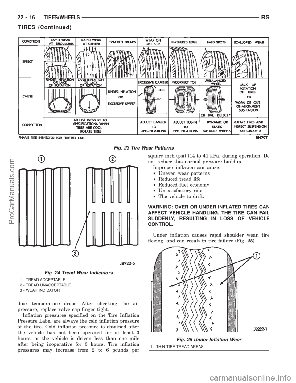
Under inflation will cause wear on the shoulders of
tire. Over inflation will cause wear at the center of
tire.
Excessive camber causes the tire to run at an
angle to the road. One side of tread is then worn
more than the other (Fig. 23).
Excessive toe-in or toe-out causes wear on the
tread edges and a feathered effect across the tread
(Fig. 23).
DIAGNOSIS AND TESTING - TREAD WEAR
INDICATORS
Tread wear indicators are molded into the bottom
of the tread grooves. When tread depth is 1.6 mm
(1/16 in.), the tread wear indicators will appear as a
13 mm (1/2 in.) band (Fig. 24).
Tire replacement is necessary when indicators
appear in two or more grooves or if localized balding
occurs.
STANDARD PROCEDURE
STANDARD PROCEDURE - TIRE INFLATION
PRESSURES
The specified tire pressures have been chosen to
provide safe operation, vehicle stability, and a smooth
ride. The proper tire pressure specification can be
found on the Tire Inflation Pressure Label provided
with the vehicle (usually on the rear face of the driv-
er's door).
A quality air pressure gauge is recommended to
check tire air pressure. Tire pressure should be
checked cold once per month. Check tire pressure
more frequently when the weather temperature var-
ies widely. Tire pressure will decrease when the out-
22 - 14 TIRES/WHEELSRS
TIRES (Continued)
ProCarManuals.com
Page 1977 of 2399
door temperature drops. After checking the air
pressure, replace valve cap finger tight.
Inflation pressures specified on the Tire Inflation
Pressure Label are always the cold inflation pressure
of the tire. Cold inflation pressure is obtained after
the vehicle has not been operated for at least 3
hours, or the vehicle is driven less than one mile
after being inoperative for 3 hours. Tire inflation
pressures may increase from 2 to 6 pounds persquare inch (psi) (14 to 41 kPa) during operation. Do
not reduce this normal pressure buildup.
Improper inflation can cause:
²Uneven wear patterns
²Reduced tread life
²Reduced fuel economy
²Unsatisfactory ride
²The vehicle to drift.
WARNING: OVER OR UNDER INFLATED TIRES CAN
AFFECT VEHICLE HANDLING. THE TIRE CAN FAIL
SUDDENLY, RESULTING IN LOSS OF VEHICLE
CONTROL.
Under inflation causes rapid shoulder wear, tire
flexing, and can result in tire failure (Fig. 25).
Fig. 23 Tire Wear Patterns
Fig. 24 Tread Wear Indicators
1 - TREAD ACCEPTABLE
2 - TREAD UNACCEPTABLE
3 - WEAR INDICATOR
Fig. 25 Under Inflation Wear
1 - THIN TIRE TREAD AREAS
22 - 16 TIRES/WHEELSRS
TIRES (Continued)
ProCarManuals.com