2002 CHRYSLER CARAVAN warning
[x] Cancel search: warningPage 2091 of 2399
(4) Remove A-pillar trim panels.
(5) Disconnect wire connectors to windshield
defroster grid.
(6) Place protective covers over instrument panel
and hood.
(7) Remove windshield molding. Using pliers, pull
outward on molding at the bottom of A-pillars.
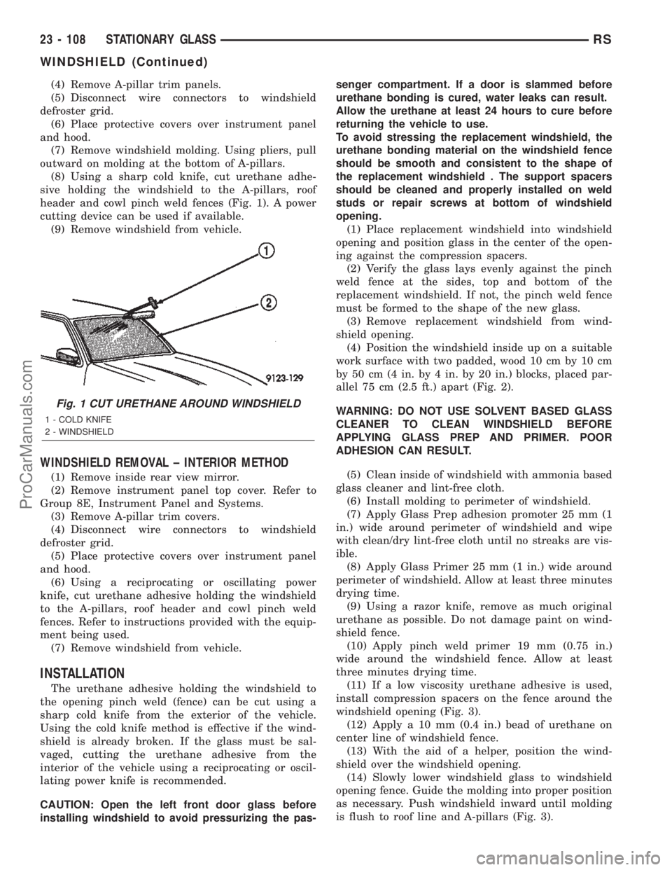
(8) Using a sharp cold knife, cut urethane adhe-
sive holding the windshield to the A-pillars, roof
header and cowl pinch weld fences (Fig. 1). A power
cutting device can be used if available.
(9) Remove windshield from vehicle.
WINDSHIELD REMOVAL ± INTERIOR METHOD
(1) Remove inside rear view mirror.
(2) Remove instrument panel top cover. Refer to
Group 8E, Instrument Panel and Systems.
(3) Remove A-pillar trim covers.
(4) Disconnect wire connectors to windshield
defroster grid.
(5) Place protective covers over instrument panel
and hood.
(6) Using a reciprocating or oscillating power
knife, cut urethane adhesive holding the windshield
to the A-pillars, roof header and cowl pinch weld
fences. Refer to instructions provided with the equip-
ment being used.
(7) Remove windshield from vehicle.
INSTALLATION
The urethane adhesive holding the windshield to
the opening pinch weld (fence) can be cut using a
sharp cold knife from the exterior of the vehicle.
Using the cold knife method is effective if the wind-
shield is already broken. If the glass must be sal-
vaged, cutting the urethane adhesive from the
interior of the vehicle using a reciprocating or oscil-
lating power knife is recommended.
CAUTION: Open the left front door glass before
installing windshield to avoid pressurizing the pas-senger compartment. If a door is slammed before
urethane bonding is cured, water leaks can result.
Allow the urethane at least 24 hours to cure before
returning the vehicle to use.
To avoid stressing the replacement windshield, the
urethane bonding material on the windshield fence
should be smooth and consistent to the shape of
the replacement windshield . The support spacers
should be cleaned and properly installed on weld
studs or repair screws at bottom of windshield
opening.
(1) Place replacement windshield into windshield
opening and position glass in the center of the open-
ing against the compression spacers.
(2) Verify the glass lays evenly against the pinch
weld fence at the sides, top and bottom of the
replacement windshield. If not, the pinch weld fence
must be formed to the shape of the new glass.
(3) Remove replacement windshield from wind-
shield opening.
(4) Position the windshield inside up on a suitable
work surface with two padded, wood 10 cm by 10 cm
by 50 cm (4 in. by 4 in. by 20 in.) blocks, placed par-
allel 75 cm (2.5 ft.) apart (Fig. 2).
WARNING: DO NOT USE SOLVENT BASED GLASS
CLEANER TO CLEAN WINDSHIELD BEFORE
APPLYING GLASS PREP AND PRIMER. POOR
ADHESION CAN RESULT.
(5) Clean inside of windshield with ammonia based
glass cleaner and lint-free cloth.
(6) Install molding to perimeter of windshield.
(7) Apply Glass Prep adhesion promoter 25 mm (1
in.) wide around perimeter of windshield and wipe
with clean/dry lint-free cloth until no streaks are vis-
ible.
(8) Apply Glass Primer 25 mm (1 in.) wide around
perimeter of windshield. Allow at least three minutes
drying time.
(9) Using a razor knife, remove as much original
urethane as possible. Do not damage paint on wind-
shield fence.
(10) Apply pinch weld primer 19 mm (0.75 in.)
wide around the windshield fence. Allow at least
three minutes drying time.
(11) If a low viscosity urethane adhesive is used,
install compression spacers on the fence around the
windshield opening (Fig. 3).
(12) Apply a 10 mm (0.4 in.) bead of urethane on
center line of windshield fence.
(13) With the aid of a helper, position the wind-
shield over the windshield opening.
(14) Slowly lower windshield glass to windshield
opening fence. Guide the molding into proper position
as necessary. Push windshield inward until molding
is flush to roof line and A-pillars (Fig. 3).
Fig. 1 CUT URETHANE AROUND WINDSHIELD
1 - COLD KNIFE
2 - WINDSHIELD
23 - 108 STATIONARY GLASSRS
WINDSHIELD (Continued)
ProCarManuals.com
Page 2094 of 2399
(1) Place replacement glass into rear window open-
ing.
(2) Verify the glass lays evenly against the pinch
weld fence at the sides, top and bottom of the
replacement rear window. If not, the fence must be
formed to the shape of the new glass.
(3) Using a grease pencil, mark the glass and lift-
gate in several locations to aid installation.
(4) Remove replacement glass from liftgate open-
ing.
(5) Position the rear window inside up on a suit-
able work surface with two padded, wood 10 cm by
10 cm by 50 cm (4 in. by 4 in. by 20 in.) blocks,
placed parallel 75 cm (2.5 ft.) apart (Fig. 2).
WARNING: DO NOT USE SOLVENT BASED GLASS
CLEANER TO CLEAN REAR WINDOW BEFORE
APPLYING GLASS PREP AND PRIMER. POOR
ADHESION CAN RESULT.
(6) Clean inside of rear window with ammonia
based glass cleaner and lint-free cloth.
(7) Apply molding to top and bottom of rear win-
dow.
(8) Apply Glass Prep adhesion promoter 25 mm (1
in.) wide around perimeter of rear window and wipe
with clean/dry lint-free cloth until no streaks are vis-
ible.
(9) Apply Glass Primer 25 mm (1 in.) wide around
perimeter of rear window. Allow at least three min-
utes drying time.
(10) Apply Pinch weld Primer 19 mm (0.75 in.)
wide around the rear window fence. Allow at least
three minutes drying time.
(11) If a low viscosity urethane adhesive is used,
install compression spacers on the fence around the
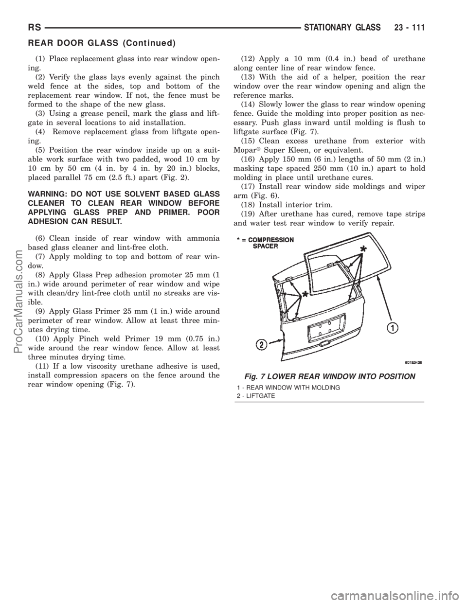
rear window opening (Fig. 7).(12) Apply a 10 mm (0.4 in.) bead of urethane
along center line of rear window fence.
(13) With the aid of a helper, position the rear
window over the rear window opening and align the
reference marks.
(14) Slowly lower the glass to rear window opening
fence. Guide the molding into proper position as nec-
essary. Push glass inward until molding is flush to
liftgate surface (Fig. 7).
(15) Clean excess urethane from exterior with
MopartSuper Kleen, or equivalent.
(16) Apply 150 mm (6 in.) lengths of 50 mm (2 in.)
masking tape spaced 250 mm (10 in.) apart to hold
molding in place until urethane cures.
(17) Install rear window side moldings and wiper
arm (Fig. 6).
(18) Install interior trim.
(19) After urethane has cured, remove tape strips
and water test rear window to verify repair.
Fig. 7 LOWER REAR WINDOW INTO POSITION
1 - REAR WINDOW WITH MOLDING
2 - LIFTGATE
RSSTATIONARY GLASS23 - 111
REAR DOOR GLASS (Continued)
ProCarManuals.com
Page 2248 of 2399
control rear set temp button is pressed simulta-
neously with the rear control head, then the front
control head press events shall have priority, i.e. if
the front user presses Rear Set Temp down and the
rear user presses Set Temp up, then the rear set
temp will decrease.
DIAGNOSIS AND TESTING
DIAGNOSIS AND TESTING - A/C COOL DOWN
TEST
The heater-A/C control module can perform an A/C
cool down test, which is a test performed during the
manufacturing process to confirm that the air condi-
tioning system is performing satisfactorily. This test
can also provide a quick confirmation of air condi-
tioning system performance to the service technician.
If the test is completed satisfactorily, no further ser-
vice is required. If the test is failed, proceed to the
A/C Performance Test to confirm the a/c system is
operating properly, or use a DRBIIItscan tool to
diagnose the A/C system control and distribution sys-
tems. Refer to the appropriate diagnostic informa-
tion.
MANUAL TEMPERATURE CONTROL
The front blower speed and rear blower speed (if
equipped with rear HVAC) must be set to High and
the evaporator temperature sensor must be greater
than 55É F or the test will fail immediately. The test
is activated by depressing the A/C and PWR buttons
simultaneously and holding them depressed for no
less than five seconds. The PWR and A/C LEDs will
blink on and off until the test is complete. If the
LEDs stop blinking before two minutes, then the cool
down test has been completed successfully. If the two
minutes expire without the expansion valve temper-
ature reaching 20É F less than the outside air tem-
perature, then the cool down test has been failed and
further A/C system diagnosis is required. If the test
is failed, the LEDs will continue to blink until the
vehicle has been driven for greater than (8 miles).
AUTOMATIC TEMPERATURE CONTROL
The ambient air temperature in the room where
the vehicle will be tested must be a minimum of 21É
C (70ÉF) for this test. The test is activated by
depressing the A/C and PWR buttons simultaneously
and holding them depressed for no less than four sec-
onds. The snowflake icon and the DELAY text in the
ATC display will blink on and off alternately until
the test is complete. If the snowflake icon and the
DELAY text stop blinking before two minutes, then
the cool down test has been completed successfully. If
the two minutes expire without the evaporator tem-perature reaching 20É F less than the evaporator ini-
tial temperature, then the cool down test has been
failed and further A/C system diagnosis is required.
If the test is failed, the snowflake icon and the
DELAY text will continue to blink across ignition
cycles until the vehicle has been driven for greater
than (8 miles).
DIAGNOSIS AND TESTING - A/C
PERFORMANCE TEST
An air conditioning performance test is the best
way to determine whether the system is performing
up to standard. This test also provides valuable clues
as to the possible cause of trouble with the air con-
ditioning system. The ambient air temperature in the
location where the vehicle will be tested must be a
minimum of 21É C (70ÉF) for this test.
WARNING: REFER TO THE APPLICABLE WARN-
INGS AND CAUTIONS FOR THIS SYSTEM BEFORE
PERFORMING THE FOLLOWING OPERATION.
(Refer to 24 - HEATING & AIR CONDITIONING/
PLUMBING - FRONT - WARNING - A/C PLUMBING)
and (Refer to 24 - HEATING & AIR CONDITIONING/
PLUMBING - FRONT - CAUTION - A/C PLUMBING).
NOTE: When connecting the service equipment
coupling to the line fitting, verify that the valve of
the coupling is fully closed. This will reduce the
amount of effort required to make the connection.
(1) Connect a tachometer to monitor the engine
speed.
(2) Remove the caps from the refrigerant system
service ports and attach a manifold gauge set to
monitor the refrigerant system pressures.
(3) Set the heater-air conditioner controls so that
the compressor is engaged, the air within the vehicle
is being recirculated, the output air is directed
through the panel outlets, the temperature control is
in the full cool position, and the blower motor is oper-
ating at its highest speed.
(4) Start the engine and allow the engine to oper-
ate for about five minutes or until it reaches normal
operating temperature. Then hold the engine speed
at 1000 rpm with the compressor clutch engaged. If
the compressor clutch does not engage, proceed with
diagnosis of the compressor clutch coil. (Refer to 24 -
HEATING & AIR CONDITIONING/CONTROLS -
FRONT/COMPRESSOR CLUTCH COIL - DIAGNO-
SIS AND TESTING).
(5) Close all the vehicle windows and doors.
(6) Insert a thermometer in the left center panel
outlet and operate the engine for five minutes.
RSHEATING & AIR CONDITIONING24-5
HEATING & AIR CONDITIONING (Continued)
ProCarManuals.com
Page 2249 of 2399
(7) With the compressor clutch engaged, record the
left center panel outlet discharge air temperature,
the discharge pressure (high side service port), and
the suction pressure (low side service port). The com-
pressor clutch may cycle, depending upon the ambi-
ent temperature and humidity. If the clutch cycles,
use the readings obtained before the clutch disen-
gaged.
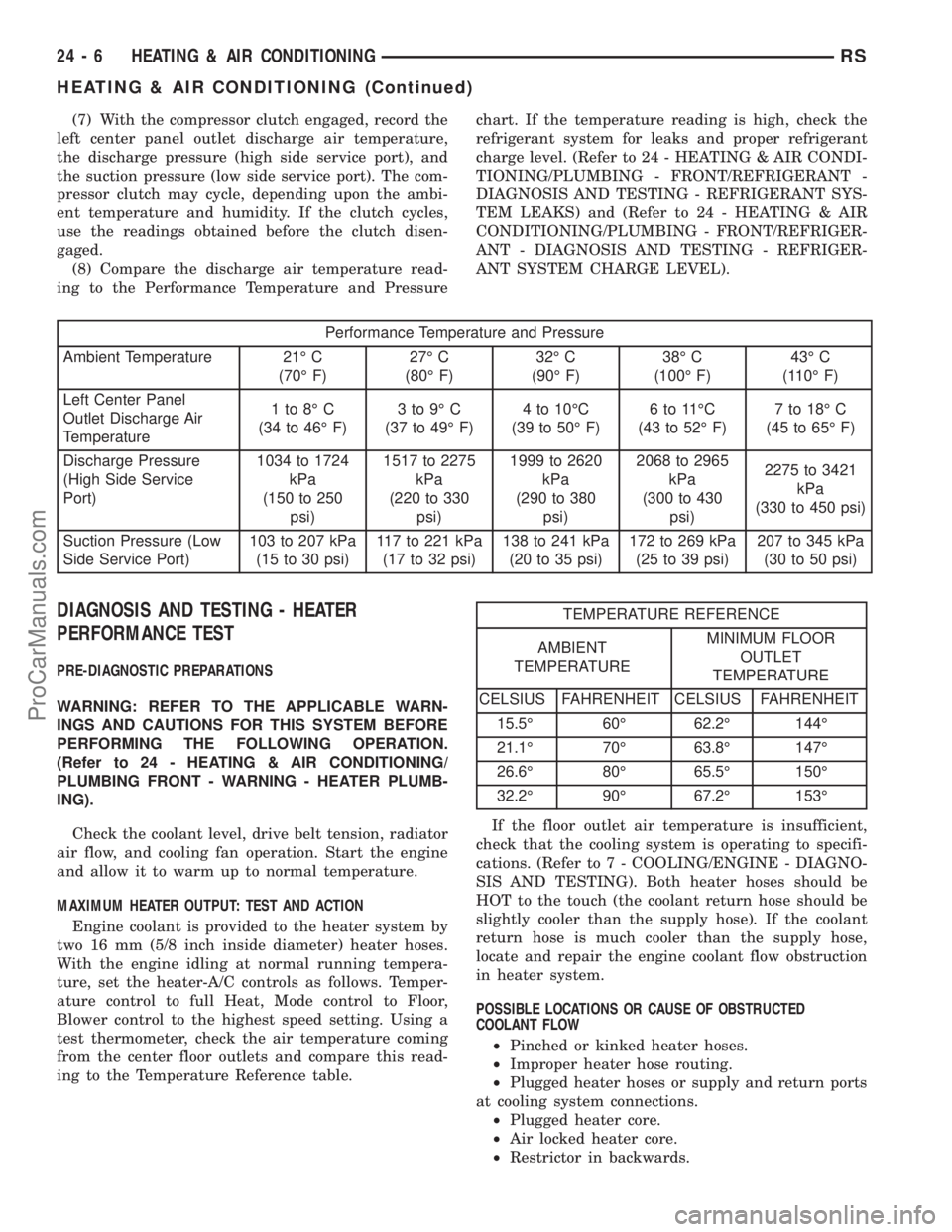
(8) Compare the discharge air temperature read-
ing to the Performance Temperature and Pressurechart. If the temperature reading is high, check the
refrigerant system for leaks and proper refrigerant
charge level. (Refer to 24 - HEATING & AIR CONDI-
TIONING/PLUMBING - FRONT/REFRIGERANT -
DIAGNOSIS AND TESTING - REFRIGERANT SYS-
TEM LEAKS) and (Refer to 24 - HEATING & AIR
CONDITIONING/PLUMBING - FRONT/REFRIGER-
ANT - DIAGNOSIS AND TESTING - REFRIGER-
ANT SYSTEM CHARGE LEVEL).
Performance Temperature and Pressure
Ambient Temperature 21É C
(70É F)27É C
(80É F)32É C
(90É F)38É C
(100É F)43É C
(110É F)
Left Center Panel
Outlet Discharge Air
Temperature1to8ÉC
(34 to 46É F)3to9ÉC
(37 to 49É F)4 to 10ÉC
(39 to 50É F)6to11ÉC
(43 to 52É F)7 to 18É C
(45 to 65É F)
Discharge Pressure
(High Side Service
Port)1034 to 1724
kPa
(150 to 250
psi)1517 to 2275
kPa
(220 to 330
psi)1999 to 2620
kPa
(290 to 380
psi)2068 to 2965
kPa
(300 to 430
psi)2275 to 3421
kPa
(330 to 450 psi)
Suction Pressure (Low
Side Service Port)103 to 207 kPa
(15 to 30 psi)117 to 221 kPa
(17 to 32 psi)138 to 241 kPa
(20 to 35 psi)172 to 269 kPa
(25 to 39 psi)207 to 345 kPa
(30 to 50 psi)
DIAGNOSIS AND TESTING - HEATER
PERFORMANCE TEST
PRE-DIAGNOSTIC PREPARATIONS
WARNING: REFER TO THE APPLICABLE WARN-
INGS AND CAUTIONS FOR THIS SYSTEM BEFORE
PERFORMING THE FOLLOWING OPERATION.
(Refer to 24 - HEATING & AIR CONDITIONING/
PLUMBING FRONT - WARNING - HEATER PLUMB-
ING).
Check the coolant level, drive belt tension, radiator
air flow, and cooling fan operation. Start the engine
and allow it to warm up to normal temperature.
MAXIMUM HEATER OUTPUT: TEST AND ACTION
Engine coolant is provided to the heater system by
two 16 mm (5/8 inch inside diameter) heater hoses.
With the engine idling at normal running tempera-
ture, set the heater-A/C controls as follows. Temper-
ature control to full Heat, Mode control to Floor,
Blower control to the highest speed setting. Using a
test thermometer, check the air temperature coming
from the center floor outlets and compare this read-
ing to the Temperature Reference table.
TEMPERATURE REFERENCE
AMBIENT
TEMPERATUREMINIMUM FLOOR
OUTLET
TEMPERATURE
CELSIUS FAHRENHEIT CELSIUS FAHRENHEIT
15.5É 60É 62.2É 144É
21.1É 70É 63.8É 147É
26.6É 80É 65.5É 150É
32.2É 90É 67.2É 153É
If the floor outlet air temperature is insufficient,
check that the cooling system is operating to specifi-
cations. (Refer to 7 - COOLING/ENGINE - DIAGNO-
SIS AND TESTING). Both heater hoses should be
HOT to the touch (the coolant return hose should be
slightly cooler than the supply hose). If the coolant
return hose is much cooler than the supply hose,
locate and repair the engine coolant flow obstruction
in heater system.
POSSIBLE LOCATIONS OR CAUSE OF OBSTRUCTED
COOLANT FLOW
²Pinched or kinked heater hoses.
²Improper heater hose routing.
²Plugged heater hoses or supply and return ports
at cooling system connections.
²Plugged heater core.
²Air locked heater core.
²Restrictor in backwards.
24 - 6 HEATING & AIR CONDITIONINGRS
HEATING & AIR CONDITIONING (Continued)
ProCarManuals.com
Page 2252 of 2399
(3) The calibration procedure should take less than
two minutes to complete for the manual heater-A/C
control, and less than twenty seconds for the ATC
heater-A/C control. When the LEDs or graphics stop
flashing, the calibration procedure is complete.
(4) If the LEDs or graphics continue to flash
beyond the normal three minute (manual) or twenty
second (ATC) calibration time, it indicates that the
heater-A/C control has detected a failure and a Diag-
nostic Trouble Code (DTC) has been set. Use a
DRBIIItscan tool to perform further diagnosis. Refer
to the appropriate diagnostic information. The LEDs
or graphics will continue to flash even after the igni-
tion switch is cycled Off and On, until a successful
calibration is completed or until the vehicle has been
driven about 13 kilometers (8 miles).
REMOVAL
WARNING: ON VEHICLES EQUIPPED WITH AIR-
BAGS, DISABLE THE AIRBAG SYSTEM BEFORE
ATTEMPTING ANY STEERING WHEEL, STEERING
COLUMN, OR INSTRUMENT PANEL COMPONENT
DIAGNOSIS OR SERVICE. DISCONNECT AND ISO-
LATE THE BATTERY NEGATIVE (GROUND) CABLE,
THEN WAIT TWO MINUTES FOR THE AIRBAG SYS-
TEM CAPACITOR TO DISCHARGE BEFORE PER-
FORMING FURTHER DIAGNOSIS OR SERVICE. THIS
IS THE ONLY SURE WAY TO DISABLE THE AIRBAG
SYSTEM. FAILURE TO TAKE THE PROPER PRE-
CAUTIONS COULD RESULT IN ACCIDENTAL AIR-
BAG DEPLOYMENT AND POSSIBLE PERSONAL
INJURY.
(1) Disconnect and isolate the battery negative
cable.
(2) Remove the center bezel from the instrument
panel. (Refer to 23 - BODY/INSTRUMENT PANEL/
INSTRUMENT PANEL CENTER BEZEL - REMOV-
AL).
(3) Place the instrument panel center bezel unit
face down on a suitable work surface. Take the
proper precautions to protect the center bezel from
cosmetic damage.
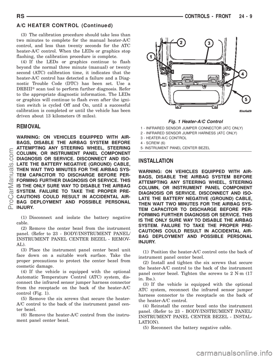
(4) If the vehicle is equipped with the optional
Automatic Temperature Control (ATC) system, dis-
connect the infrared sensor jumper harness connector
from the receptacle on the back of the heater-A/C
control (Fig. 1).
(5) Remove the six screws that secure the heater-
A/C control to the back of the instrument panel cen-
ter bezel.
(6) Remove the heater-A/C control from the instru-
ment panel center bezel.
INSTALLATION
WARNING: ON VEHICLES EQUIPPED WITH AIR-
BAGS, DISABLE THE AIRBAG SYSTEM BEFORE
ATTEMPTING ANY STEERING WHEEL, STEERING
COLUMN, OR INSTRUMENT PANEL COMPONENT
DIAGNOSIS OR SERVICE. DISCONNECT AND ISO-
LATE THE BATTERY NEGATIVE (GROUND) CABLE,
THEN WAIT TWO MINUTES FOR THE AIRBAG SYS-
TEM CAPACITOR TO DISCHARGE BEFORE PER-
FORMING FURTHER DIAGNOSIS OR SERVICE. THIS
IS THE ONLY SURE WAY TO DISABLE THE AIRBAG
SYSTEM. FAILURE TO TAKE THE PROPER PRE-
CAUTIONS COULD RESULT IN ACCIDENTAL AIR-
BAG DEPLOYMENT AND POSSIBLE PERSONAL
INJURY.
(1) Position the heater-A/C control onto the back of
instrument panel center bezel.
(2) Install and tighten the six screws that secure
the heater-A/C control to the back of the instrument
panel center bezel. Tighten the screws to 2 N´m (17
in. lbs.).
(3) If the vehicle is equipped with the optional
ATC system, reconnect the infrared sensor jumper
harness connector to the receptacle on the back of
the heater-A/C control.
(4) Reinstall the center bezel onto the instrument
panel. (Refer to 23 - BODY/INSTRUMENT PANEL/
INSTRUMENT PANEL CENTER BEZEL - INSTAL-
LATION).
(5) Reconnect the battery negative cable.
Fig. 1 Heater-A/C Control
1 - INFRARED SENSOR JUMPER CONNECTOR (ATC ONLY)
2 - INFRARED SENSOR JUMPER HARNESS (ATC ONLY)
3 - HEATER-A/C CONTROL
4 - SCREW (6)
5- INSTRUMENT PANEL CENTER BEZEL
RSCONTROLS - FRONT24-9
A/C HEATER CONTROL (Continued)
ProCarManuals.com
Page 2255 of 2399
REMOVAL
The single zone heating and air conditioning sys-
tem is equipped with a single blend door actuator.
The dual zone system has two blend door actuators,
one for the driver side blend air door and one for the
passenger side blend air door. The same service pro-
cedures can be used for each of these actuators.
WARNING: ON VEHICLES EQUIPPED WITH AIR-
BAGS, DISABLE THE AIRBAG SYSTEM BEFORE
ATTEMPTING ANY STEERING WHEEL, STEERING
COLUMN, OR INSTRUMENT PANEL COMPONENT
DIAGNOSIS OR SERVICE. DISCONNECT AND ISO-
LATE THE BATTERY NEGATIVE (GROUND) CABLE,
THEN WAIT TWO MINUTES FOR THE AIRBAG SYS-
TEM CAPACITOR TO DISCHARGE BEFORE PER-
FORMING FURTHER DIAGNOSIS OR SERVICE. THIS
IS THE ONLY SURE WAY TO DISABLE THE AIRBAG
SYSTEM. FAILURE TO TAKE THE PROPER PRE-
CAUTIONS COULD RESULT IN ACCIDENTAL AIR-
BAG DEPLOYMENT AND POSSIBLE PERSONAL
INJURY.
(1) Disconnect and isolate the battery negative
cable.
(2) Remove the silencer from beneath the driver
side end of the instrument panel. (Refer to 23 -
BODY/INSTRUMENT PANEL/INSTRUMENT
PANEL SILENCER - REMOVAL).
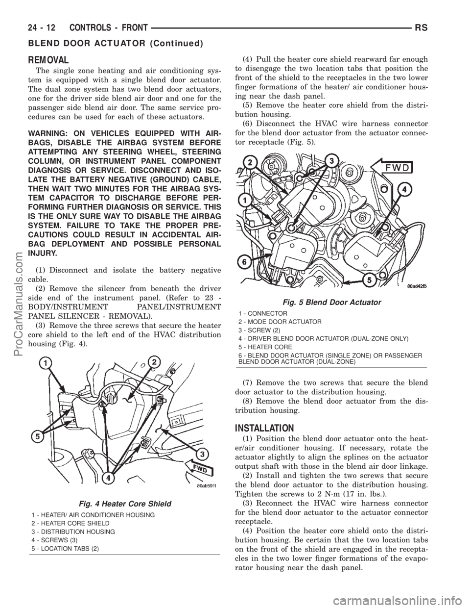
(3) Remove the three screws that secure the heater
core shield to the left end of the HVAC distribution
housing (Fig. 4).(4) Pull the heater core shield rearward far enough
to disengage the two location tabs that position the
front of the shield to the receptacles in the two lower
finger formations of the heater/ air conditioner hous-
ing near the dash panel.
(5) Remove the heater core shield from the distri-
bution housing.
(6) Disconnect the HVAC wire harness connector
for the blend door actuator from the actuator connec-
tor receptacle (Fig. 5).
(7) Remove the two screws that secure the blend
door actuator to the distribution housing.
(8) Remove the blend door actuator from the dis-
tribution housing.
INSTALLATION
(1) Position the blend door actuator onto the heat-
er/air conditioner housing. If necessary, rotate the
actuator slightly to align the splines on the actuator
output shaft with those in the blend air door linkage.
(2) Install and tighten the two screws that secure
the blend door actuator to the distribution housing.
Tighten the screws to 2 N´m (17 in. lbs.).
(3) Reconnect the HVAC wire harness connector
for the blend door actuator to the actuator connector
receptacle.
(4) Position the heater core shield onto the distri-
bution housing. Be certain that the two location tabs
on the front of the shield are engaged in the recepta-
cles in the two lower finger formations of the evapo-
rator housing near the dash panel.
Fig. 4 Heater Core Shield
1 - HEATER/ AIR CONDITIONER HOUSING
2 - HEATER CORE SHIELD
3 - DISTRIBUTION HOUSING
4 - SCREWS (3)
5 - LOCATION TABS (2)
Fig. 5 Blend Door Actuator
1 - CONNECTOR
2 - MODE DOOR ACTUATOR
3 - SCREW (2)
4 - DRIVER BLEND DOOR ACTUATOR (DUAL-ZONE ONLY)
5 - HEATER CORE
6 - BLEND DOOR ACTUATOR (SINGLE ZONE) OR PASSENGER
BLEND DOOR ACTUATOR (DUAL-ZONE)
24 - 12 CONTROLS - FRONTRS
BLEND DOOR ACTUATOR (Continued)
ProCarManuals.com
Page 2258 of 2399
BLOWER MOTOR RESISTOR
DESCRIPTION
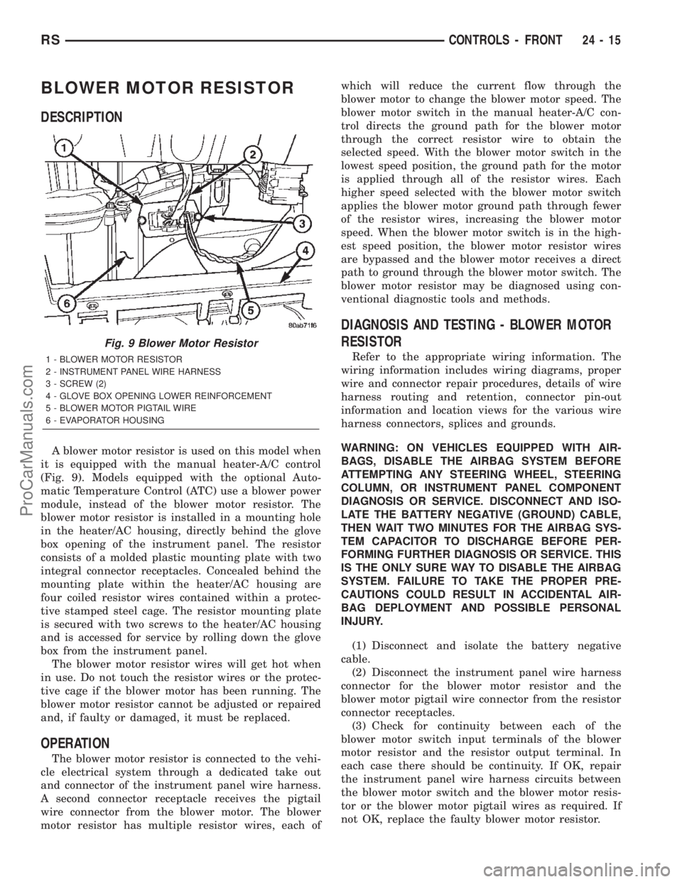
A blower motor resistor is used on this model when
it is equipped with the manual heater-A/C control
(Fig. 9). Models equipped with the optional Auto-
matic Temperature Control (ATC) use a blower power
module, instead of the blower motor resistor. The
blower motor resistor is installed in a mounting hole
in the heater/AC housing, directly behind the glove
box opening of the instrument panel. The resistor
consists of a molded plastic mounting plate with two
integral connector receptacles. Concealed behind the
mounting plate within the heater/AC housing are
four coiled resistor wires contained within a protec-
tive stamped steel cage. The resistor mounting plate
is secured with two screws to the heater/AC housing
and is accessed for service by rolling down the glove
box from the instrument panel.
The blower motor resistor wires will get hot when
in use. Do not touch the resistor wires or the protec-
tive cage if the blower motor has been running. The
blower motor resistor cannot be adjusted or repaired
and, if faulty or damaged, it must be replaced.
OPERATION
The blower motor resistor is connected to the vehi-
cle electrical system through a dedicated take out
and connector of the instrument panel wire harness.
A second connector receptacle receives the pigtail
wire connector from the blower motor. The blower
motor resistor has multiple resistor wires, each ofwhich will reduce the current flow through the
blower motor to change the blower motor speed. The
blower motor switch in the manual heater-A/C con-
trol directs the ground path for the blower motor
through the correct resistor wire to obtain the
selected speed. With the blower motor switch in the
lowest speed position, the ground path for the motor
is applied through all of the resistor wires. Each
higher speed selected with the blower motor switch
applies the blower motor ground path through fewer
of the resistor wires, increasing the blower motor
speed. When the blower motor switch is in the high-
est speed position, the blower motor resistor wires
are bypassed and the blower motor receives a direct
path to ground through the blower motor switch. The
blower motor resistor may be diagnosed using con-
ventional diagnostic tools and methods.
DIAGNOSIS AND TESTING - BLOWER MOTOR
RESISTOR
Refer to the appropriate wiring information. The
wiring information includes wiring diagrams, proper
wire and connector repair procedures, details of wire
harness routing and retention, connector pin-out
information and location views for the various wire
harness connectors, splices and grounds.
WARNING: ON VEHICLES EQUIPPED WITH AIR-
BAGS, DISABLE THE AIRBAG SYSTEM BEFORE
ATTEMPTING ANY STEERING WHEEL, STEERING
COLUMN, OR INSTRUMENT PANEL COMPONENT
DIAGNOSIS OR SERVICE. DISCONNECT AND ISO-
LATE THE BATTERY NEGATIVE (GROUND) CABLE,
THEN WAIT TWO MINUTES FOR THE AIRBAG SYS-
TEM CAPACITOR TO DISCHARGE BEFORE PER-
FORMING FURTHER DIAGNOSIS OR SERVICE. THIS
IS THE ONLY SURE WAY TO DISABLE THE AIRBAG
SYSTEM. FAILURE TO TAKE THE PROPER PRE-
CAUTIONS COULD RESULT IN ACCIDENTAL AIR-
BAG DEPLOYMENT AND POSSIBLE PERSONAL
INJURY.
(1) Disconnect and isolate the battery negative
cable.
(2) Disconnect the instrument panel wire harness
connector for the blower motor resistor and the
blower motor pigtail wire connector from the resistor
connector receptacles.
(3) Check for continuity between each of the
blower motor switch input terminals of the blower
motor resistor and the resistor output terminal. In
each case there should be continuity. If OK, repair
the instrument panel wire harness circuits between
the blower motor switch and the blower motor resis-
tor or the blower motor pigtail wires as required. If
not OK, replace the faulty blower motor resistor.
Fig. 9 Blower Motor Resistor
1 - BLOWER MOTOR RESISTOR
2 - INSTRUMENT PANEL WIRE HARNESS
3 - SCREW (2)
4 - GLOVE BOX OPENING LOWER REINFORCEMENT
5 - BLOWER MOTOR PIGTAIL WIRE
6 - EVAPORATOR HOUSING
RSCONTROLS - FRONT24-15
ProCarManuals.com
Page 2259 of 2399
REMOVAL
WARNING: ON VEHICLES EQUIPPED WITH AIR-
BAGS, DISABLE THE AIRBAG SYSTEM BEFORE
ATTEMPTING ANY STEERING WHEEL, STEERING
COLUMN, OR INSTRUMENT PANEL COMPONENT
DIAGNOSIS OR SERVICE. DISCONNECT AND ISO-
LATE THE BATTERY NEGATIVE (GROUND) CABLE,
THEN WAIT TWO MINUTES FOR THE AIRBAG SYS-
TEM CAPACITOR TO DISCHARGE BEFORE PER-
FORMING FURTHER DIAGNOSIS OR SERVICE. THIS
IS THE ONLY SURE WAY TO DISABLE THE AIRBAG
SYSTEM. FAILURE TO TAKE THE PROPER PRE-
CAUTIONS COULD RESULT IN ACCIDENTAL AIR-
BAG DEPLOYMENT AND POSSIBLE PERSONAL
INJURY.
WARNING: THE BLOWER MOTOR RESISTOR MAY
GET VERY HOT DURING NORMAL OPERATION. IF
THE BLOWER MOTOR WAS TURNED ON, WAIT
FIVE MINUTES TO ALLOW THE BLOWER MOTOR
RESISTOR TO COOL BEFORE PERFORMING DIAG-
NOSIS OR SERVICE. FAILURE TO TAKE THIS PRE-
CAUTION CAN RESULT IN PERSONAL INJURY.
CAUTION: Do not operate the blower motor with the
blower motor resistor removed from the circuit.
Failure to take this precaution can result in vehicle
damage.
(1) Disconnect and isolate the battery negative
cable.
(2) Open the glove box.
(3) Flex both sides of the glove box bin inward
near the top far enough for the rubber glove box stop
bumpers to clear the sides of the glove box opening,
then roll the glove box downward.
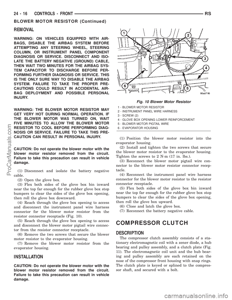
(4) Reach through the glove box opening to access
and disconnect the instrument panel wire harness
connector for the blower motor resistor from the
resistor connector receptacle (Fig. 10).
(5) Reach through the glove box opening to access
and disconnect the blower motor pigtail wire connec-
tor from the resistor connector receptacle.
(6) Remove the two screws that secure the blower
motor resistor to the evaporator housing.
(7) Remove the blower motor resistor from the
evaporator housing.
INSTALLATION
CAUTION: Do not operate the blower motor with the
blower motor resistor removed from the circuit.
Failure to take this precaution can result in vehicle
damage.(1) Position the blower motor resistor into the
evaporator housing.
(2) Install and tighten the two screws that secure
the blower motor resistor to the evaporator housing.
Tighten the screws to 2 N´m (17 in. lbs.).
(3) Reconnect the blower motor pigtail wire con-
nector to the blower motor resistor connector recep-
tacle.
(4) Reconnect the instrument panel wire harness
connector for the blower motor resistor to the resistor
connector receptacle.
(5) Flex both sides of the glove box bin inward
near the top far enough for the rubber glove box stop
bumpers to clear the sides of the glove box opening,
then roll the glove box upward.
(6) Close and latch the glove box.
(7) Reconnect the battery negative cable.
COMPRESSOR CLUTCH
DESCRIPTION
The compressor clutch assembly consists of a sta-
tionary electromagnetic coil with a zener diode, a hub
bearing and pulley assembly, and a clutch plate (Fig.
11). The electromagnetic coil unit and the hub bear-
ing and pulley assembly are each retained on the
nose of the compressor front housing with snap rings.
The clutch plate is keyed or splined to the compres-
sor shaft, and secured with a bolt.
Fig. 10 Blower Motor Resistor
1 - BLOWER MOTOR RESISTOR
2 - INSTRUMENT PANEL WIRE HARNESS
3 - SCREW (2)
4 - GLOVE BOX OPENING LOWER REINFORCEMENT
5 - BLOWER MOTOR PIGTAIL WIRE
6 - EVAPORATOR HOUSING
24 - 16 CONTROLS - FRONTRS
BLOWER MOTOR RESISTOR (Continued)
ProCarManuals.com