2002 CHRYSLER CARAVAN suspension
[x] Cancel search: suspensionPage 1551 of 2399
CAUTION: Power steering fluid hoses must remain
away from the exhaust system and must not come
in contact with any unfriendly surfaces on the vehi-
cle.
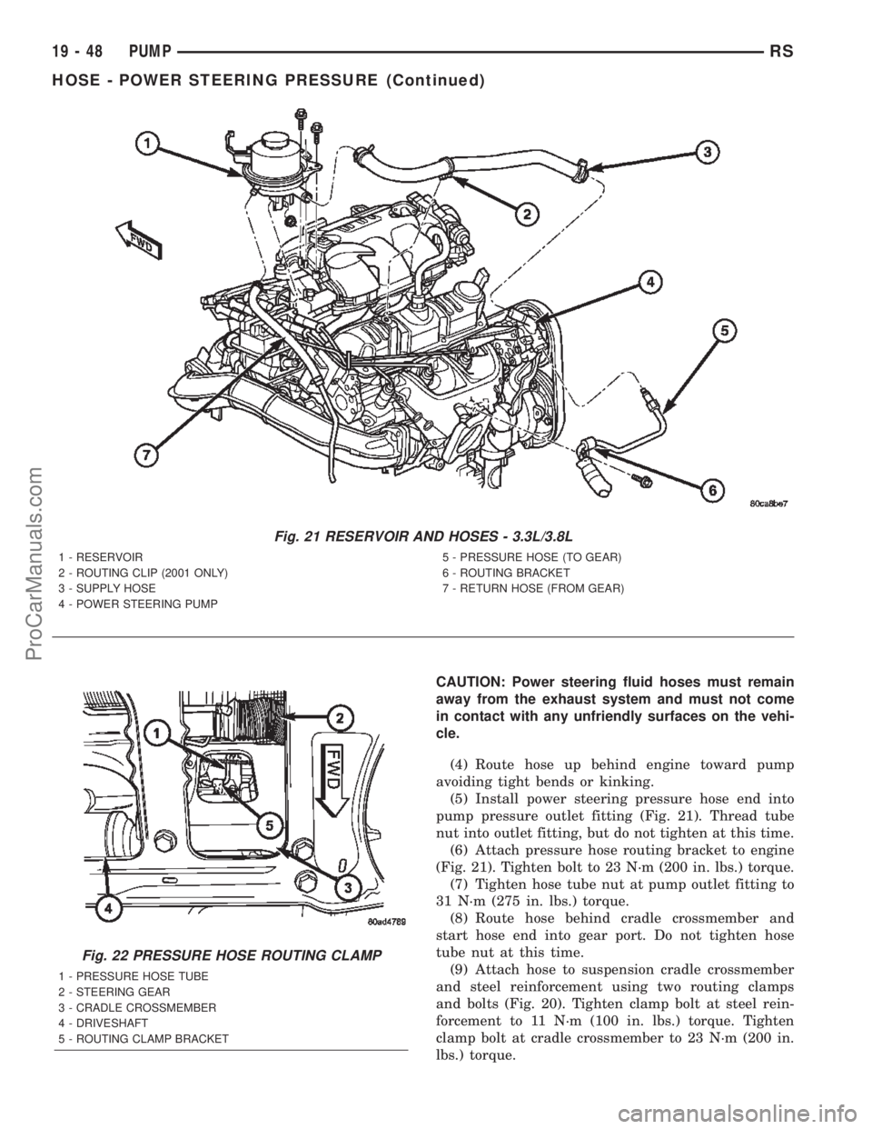
(4) Route hose up behind engine toward pump
avoiding tight bends or kinking.
(5) Install power steering pressure hose end into
pump pressure outlet fitting (Fig. 21). Thread tube
nut into outlet fitting, but do not tighten at this time.
(6) Attach pressure hose routing bracket to engine
(Fig. 21). Tighten bolt to 23 N´m (200 in. lbs.) torque.
(7) Tighten hose tube nut at pump outlet fitting to
31 N´m (275 in. lbs.) torque.
(8) Route hose behind cradle crossmember and
start hose end into gear port. Do not tighten hose
tube nut at this time.
(9) Attach hose to suspension cradle crossmember
and steel reinforcement using two routing clamps
and bolts (Fig. 20). Tighten clamp bolt at steel rein-
forcement to 11 N´m (100 in. lbs.) torque. Tighten
clamp bolt at cradle crossmember to 23 N´m (200 in.
lbs.) torque.
Fig. 21 RESERVOIR AND HOSES - 3.3L/3.8L
1 - RESERVOIR
2 - ROUTING CLIP (2001 ONLY)
3 - SUPPLY HOSE
4 - POWER STEERING PUMP5 - PRESSURE HOSE (TO GEAR)
6 - ROUTING BRACKET
7 - RETURN HOSE (FROM GEAR)
Fig. 22 PRESSURE HOSE ROUTING CLAMP
1 - PRESSURE HOSE TUBE
2 - STEERING GEAR
3 - CRADLE CROSSMEMBER
4 - DRIVESHAFT
5 - ROUTING CLAMP BRACKET
19 - 48 PUMPRS
HOSE - POWER STEERING PRESSURE (Continued)
ProCarManuals.com
Page 1552 of 2399
(10) Tighten hose tube nut at power steering gear
port to 31 N´m (275 in. lbs.) torque.
(11) Install front emissions vapor canister. (Refer
to 25 - EMISSIONS CONTROL/EVAPORATIVE
EMISSIONS/VAPOR CANISTER - INSTALLATION)
(12) Lower vehicle.
(13) Fill and bleed the power steering system
using the Power Steering Pump Initial Operation
Procedure. (Refer to 19 - STEERING/PUMP - STAN-
DARD PROCEDURE)
(14) Inspect system for leaks.
HOSE - POWER STEERING
RETURN
REMOVAL
REMOVAL - 2.4L ENGINE
NOTE: Before proceeding, review all WARNINGS
and CAUTIONS. (Refer to 19 - STEERING/PUMP -
WARNING)(Refer to 19 - STEERING/PUMP - CAU-
TION)
(1) Remove cap from power steering fluid reser-
voir.
(2) Using a siphon pump, remove as much power
steering fluid as possible from power steering fluid
reservoir.
(3) Raise vehicle. (Refer to LUBRICATION &
MAINTENANCE/HOISTING - STANDARD PROCE-
DURE)
(4) Remove front emissions vapor canister. (Refer
to 25 - EMISSIONS CONTROL/EVAPORATIVE
EMISSIONS/VAPOR CANISTER - REMOVAL)
(5) Place an oil drain pan under vehicle to catch
power steering fluid.
(6) Cut tie-strap securing insulating heat sleeve to
power steering fluid return hose near power steering
pump. Pull back heat sleeve to expose hose clamp.
(7) Remove clamp, then return hose from power
steering pump (Fig. 19).
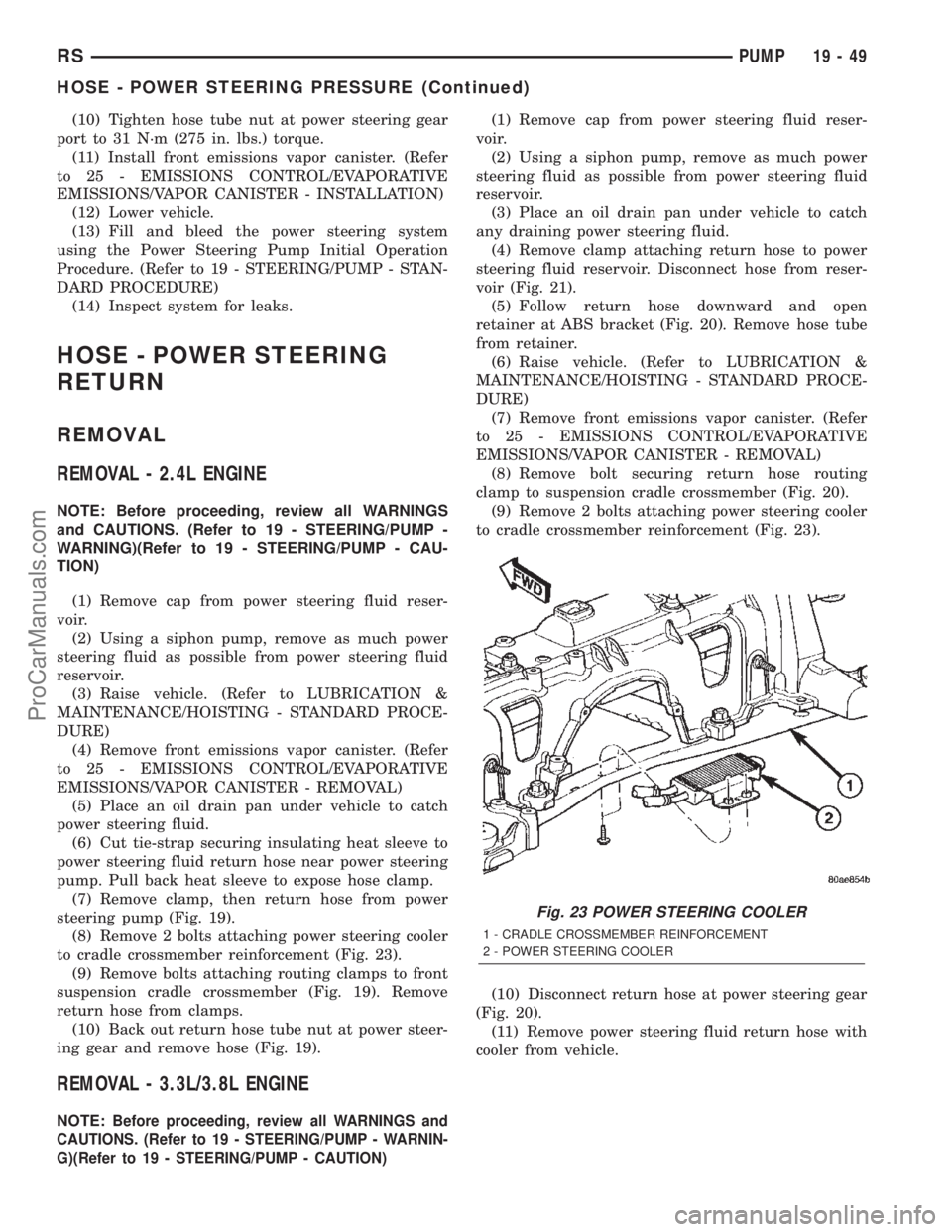
(8) Remove 2 bolts attaching power steering cooler
to cradle crossmember reinforcement (Fig. 23).
(9) Remove bolts attaching routing clamps to front
suspension cradle crossmember (Fig. 19). Remove
return hose from clamps.
(10) Back out return hose tube nut at power steer-
ing gear and remove hose (Fig. 19).
REMOVAL - 3.3L/3.8L ENGINE
NOTE:Before proceeding, review all WARNINGS and
CAUTIONS. (Refer to 19 - STEERING/PUMP - WARNIN-
G)(Refer to 19 - STEERING/PUMP - CAUTION)
(1) Remove cap from power steering fluid reser-
voir.
(2) Using a siphon pump, remove as much power
steering fluid as possible from power steering fluid
reservoir.
(3) Place an oil drain pan under vehicle to catch
any draining power steering fluid.
(4) Remove clamp attaching return hose to power
steering fluid reservoir. Disconnect hose from reser-
voir (Fig. 21).
(5) Follow return hose downward and open
retainer at ABS bracket (Fig. 20). Remove hose tube
from retainer.
(6) Raise vehicle. (Refer to LUBRICATION &
MAINTENANCE/HOISTING - STANDARD PROCE-
DURE)
(7) Remove front emissions vapor canister. (Refer
to 25 - EMISSIONS CONTROL/EVAPORATIVE
EMISSIONS/VAPOR CANISTER - REMOVAL)
(8) Remove bolt securing return hose routing
clamp to suspension cradle crossmember (Fig. 20).
(9) Remove 2 bolts attaching power steering cooler
to cradle crossmember reinforcement (Fig. 23).
(10) Disconnect return hose at power steering gear
(Fig. 20).
(11) Remove power steering fluid return hose with
cooler from vehicle.
Fig. 23 POWER STEERING COOLER
1 - CRADLE CROSSMEMBER REINFORCEMENT
2 - POWER STEERING COOLER
RSPUMP19-49
HOSE - POWER STEERING PRESSURE (Continued)
ProCarManuals.com
Page 1553 of 2399
INSTALLATION
INSTALLATION - 2.4L ENGINE
(1) Remove any used O-rings from ends of power
steering hose.
(2) Using a lint free towel, wipe clean hose ends,
power steering pump fitting and steering gear port.
(3) Install new O-ring on power steering gear end
of return hose. Lubricate O-ring using clean power
steering fluid.
CAUTION: Use care not to bend tube ends of the
power steering hoses when installing. Leaks and
restrictions may occur.
CAUTION: If a new return hose is being installed
and it does not have an insulating heat sleeve
installed, the heat shield from the original hose
must be transferred before hose installation.
(4) Route hose along rear of cradle crossmember
and start gear end of hose into gear port. Do not
tighten hose tube nut at this time.
(5) Attach hose to suspension cradle crossmember
using two routing clamps and bolts (Fig. 19). Tighten
clamp bolts to 23 N´m (200 in. lbs.) torque.
(6) Tighten return hose tube nut at power steering
gear port to 31 N´m (275 in. lbs.) torque.
(7) Install the power steering fluid cooler on the
cradle crossmember reinforcement (Fig. 23). Install
the mounting bolts and tighten to 11 N´m (100 in.
lbs.).
CAUTION: Power steering fluid hoses must remain
away from the exhaust system and must not come
in contact with any unfriendly surfaces on the vehi-
cle.
(8) Route pump end of hose over cradle crossmem-
ber toward pump avoiding tight bends or kinking.
(9) Install return hose onto power steering pump
return fitting and secure with hose clamp (Fig. 19).
Tighten the screw-type clamp to a torque of 2 N´m
(18 in. lbs.).
CAUTION: To prevent overheating of power steering
fluid return hose, protective heat shield sleeve must
cover entire rubber hose.
(10) Slide insulating heat shield up over the clamp
on the return hose and tie-strap it in place.
(11) Install front emissions vapor canister. (Refer
to 25 - EMISSIONS CONTROL/EVAPORATIVE
EMISSIONS/VAPOR CANISTER - INSTALLATION)
(12) Lower vehicle.(13) Fill and bleed the power steering system
using the Power Steering Pump Initial Operation
Procedure. (Refer to 19 - STEERING/PUMP - STAN-
DARD PROCEDURE)
(14) Inspect system for leaks.
INSTALLATION - 3.3L/3.8L ENGINE
(1) Remove any used O-rings from ends of power
steering hose.
(2) Using a lint free towel, wipe clean hose ends
and power steering gear hose port.
(3) Install a new O-ring on gear port end of power
steering fluid hose. Lubricate O-ring using clean
power steering fluid.
CAUTION: Use care not to bend tube ends of the
power steering hoses when installing. Leaks and
restrictions may occur.
CAUTION: Power steering fluid hoses must remain
away from the exhaust system and must not come
in contact with any unfriendly surfaces on the vehi-
cle.
(4) Route hose (with cooler attached) up toward
reservoir avoiding tight bends or kinking.
(5) Start steering gear end of hose into gear port.
Do not tighten hose tube nut at this time.
(6) Attach return hose tubes to suspension cradle
crossmember using routing clamp and bolt (Fig. 20).
Tighten clamp bolt to 23 N´m (200 in. lbs.) torque.
(7) Install the power steering fluid cooler on the
cradle crossmember reinforcement (Fig. 23). Install
the mounting bolts and tighten to 11 N´m (100 in.
lbs.). When installing mounting bolts, include pres-
sure hose routing clamp.
(8) Tighten hose tube nut at power steering gear
port to 31 N´m (275 in. lbs.) torque.
(9) Install front emissions vapor canister. (Refer to
25 - EMISSIONS CONTROL/EVAPORATIVE EMIS-
SIONS/VAPOR CANISTER - INSTALLATION)
(10) Lower vehicle.
(11) Install return hose tube into retainer on ABS
bracket (Fig. 20). Close the bracket.
(12) Install return hose onto reservoir (Fig. 21).
Slide the hose clamp into position on fluid reservoir
and attach it.Be sure hose clamp in installed
past bead on fluid reservoir fitting.
(13) Fill and bleed power steering system using
the Power Steering Pump Initial Operation Proce-
dure. (Refer to 19 - STEERING/PUMP - STANDARD
PROCEDURE)
(14) Inspect system for leaks.
19 - 50 PUMPRS
HOSE - POWER STEERING RETURN (Continued)
ProCarManuals.com
Page 2038 of 2399
FRONT WHEELHOUSE
SPLASH SHIELD
REMOVAL
(1) Hoist and support vehicle on safety stands.
(Refer to LUBRICATION & MAINTENANCE/HOIST-
ING - STANDARD PROCEDURE).
(2) Remove front wheel.
(3) Remove push pin fasteners attaching splash
shield to frame rail forward of suspension.
(4) Remove push pin fasteners attaching splash
shield to frame rail rearward of suspension.
(5) Remove screws attaching wheelhouse splash
shield to front fender and front bumper fascia.
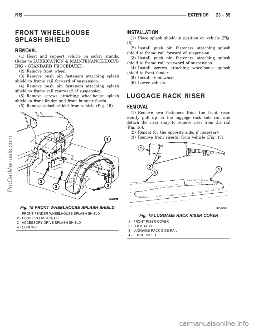
(6) Remove splash shield from vehicle (Fig. 15).
INSTALLATION
(1) Place splash shield in position on vehicle (Fig.
15).
(2) Install push pin fasteners attaching splash
shield to frame rail forward of suspension.
(3) Install push pin fasteners attaching splash
shield to frame rail rearward of suspension.
(4) Install screws attaching wheelhouse splash
shield to front fender.
(5) Install front wheel.
(6) Lower vehicle.
LUGGAGE RACK RISER
REMOVAL
(1) Remove two fasteners from the front riser.
Gently pull up on the luggage rack side rail and
detach the riser snap to remove riser from the rail
(Fig. 16).
(2) Repeat for the opposite side, if necessary.
(3) Remove front riser(s) from vehicle (Fig. 17).
Fig. 15 FRONT WHEELHOUSE SPLASH SHIELD
1 - FRONT FENDER WHEELHOUSE SPLASH SHIELD
2 - PUSH PIN FASTENERS
3 - ACCESSORY DRIVE SPLASH SHIELD
4 - SCREWSFig. 16 LUGGAGE RACK RISER COVER
1 - FRONT RISER COVER
2 - LOCK TABS
3 - LUGGAGE RACK SIDE RAIL
4 - FRONT RISER
RSEXTERIOR23-55
ProCarManuals.com
Page 2130 of 2399
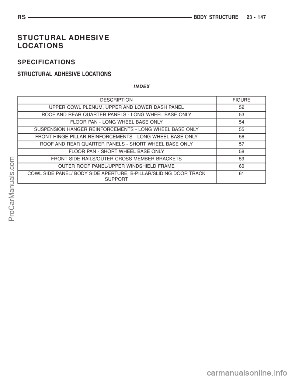
STUCTURAL ADHESIVE
LOCATIONS
SPECIFICATIONS
STRUCTURAL ADHESIVE LOCATIONS
INDEX
DESCRIPTION FIGURE
UPPER COWL PLENUM, UPPER AND LOWER DASH PANEL 52
ROOF AND REAR QUARTER PANELS - LONG WHEEL BASE ONLY 53
FLOOR PAN - LONG WHEEL BASE ONLY 54
SUSPENSION HANGER REINFORCEMENTS - LONG WHEEL BASE ONLY 55
FRONT HINGE PILLAR REINFORCEMENTS - LONG WHEEL BASE ONLY 56
ROOF AND REAR QUARTER PANELS - SHORT WHEEL BASE ONLY 57
FLOOR PAN - SHORT WHEEL BASE ONLY 58
FRONT SIDE RAILS/OUTER CROSS MEMBER BRACKETS 59
OUTER ROOF PANEL/UPPER WINDSHIELD FRAME 60
COWL SIDE PANEL/ BODY SIDE APERTURE, B-PILLAR/SLIDING DOOR TRACK
SUPPORT61
RSBODY STRUCTURE23 - 147
ProCarManuals.com
Page 2134 of 2399
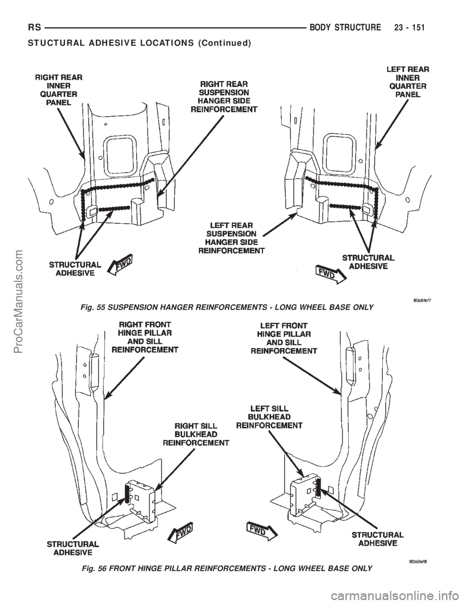
Fig. 55 SUSPENSION HANGER REINFORCEMENTS - LONG WHEEL BASE ONLY
Fig. 56 FRONT HINGE PILLAR REINFORCEMENTS - LONG WHEEL BASE ONLY
RSBODY STRUCTURE23 - 151
STUCTURAL ADHESIVE LOCATIONS (Continued)
ProCarManuals.com
Page 2139 of 2399
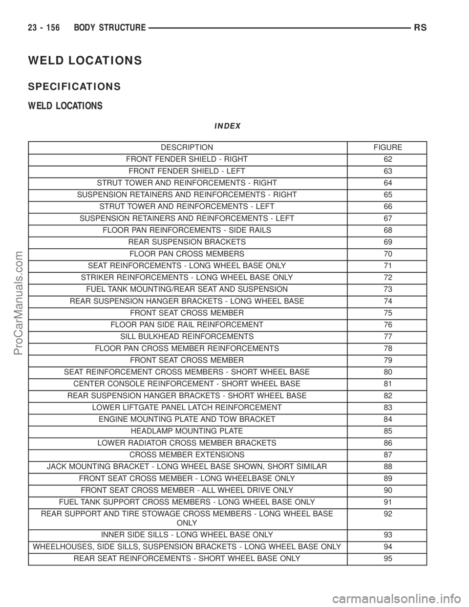
WELD LOCATIONS
SPECIFICATIONS
WELD LOCATIONS
INDEX
DESCRIPTION FIGURE
FRONT FENDER SHIELD - RIGHT 62
FRONT FENDER SHIELD - LEFT 63
STRUT TOWER AND REINFORCEMENTS - RIGHT 64
SUSPENSION RETAINERS AND REINFORCEMENTS - RIGHT 65
STRUT TOWER AND REINFORCEMENTS - LEFT 66
SUSPENSION RETAINERS AND REINFORCEMENTS - LEFT 67
FLOOR PAN REINFORCEMENTS - SIDE RAILS 68
REAR SUSPENSION BRACKETS 69
FLOOR PAN CROSS MEMBERS 70
SEAT REINFORCEMENTS - LONG WHEEL BASE ONLY 71
STRIKER REINFORCEMENTS - LONG WHEEL BASE ONLY 72
FUEL TANK MOUNTING/REAR SEAT AND SUSPENSION 73
REAR SUSPENSION HANGER BRACKETS - LONG WHEEL BASE 74
FRONT SEAT CROSS MEMBER 75
FLOOR PAN SIDE RAIL REINFORCEMENT 76
SILL BULKHEAD REINFORCEMENTS 77
FLOOR PAN CROSS MEMBER REINFORCEMENTS 78
FRONT SEAT CROSS MEMBER 79
SEAT REINFORCEMENT CROSS MEMBERS - SHORT WHEEL BASE 80
CENTER CONSOLE REINFORCEMENT - SHORT WHEEL BASE 81
REAR SUSPENSION HANGER BRACKETS - SHORT WHEEL BASE 82
LOWER LIFTGATE PANEL LATCH REINFORCEMENT 83
ENGINE MOUNTING PLATE AND TOW BRACKET 84
HEADLAMP MOUNTING PLATE 85
LOWER RADIATOR CROSS MEMBER BRACKETS 86
CROSS MEMBER EXTENSIONS 87
JACK MOUNTING BRACKET - LONG WHEEL BASE SHOWN, SHORT SIMILAR 88
FRONT SEAT CROSS MEMBER - LONG WHEELBASE ONLY 89
FRONT SEAT CROSS MEMBER - ALL WHEEL DRIVE ONLY 90
FUEL TANK SUPPORT CROSS MEMBERS - LONG WHEEL BASE ONLY 91
REAR SUPPORT AND TIRE STOWAGE CROSS MEMBERS - LONG WHEEL BASE
ONLY92
INNER SIDE SILLS - LONG WHEEL BASE ONLY 93
WHEELHOUSES, SIDE SILLS, SUSPENSION BRACKETS - LONG WHEEL BASE ONLY 94
REAR SEAT REINFORCEMENTS - SHORT WHEEL BASE ONLY 95
23 - 156 BODY STRUCTURERS
ProCarManuals.com
Page 2141 of 2399

DESCRIPTION FIGURE
LATCH REINFORCEMENT AND OUTER WHEELHOUSE - SHORT WHEEL BASE ONLY 137
D-PILLAR REINFORCEMENT - SHORT WHEEL BASE ONLY 138
OUTER WHEELHOUSE - SHORT WHEEL BASE ONLY 139
LEFT REAR INNER QUARTER PANEL - SHORT WHEEL BASE ONLY 140
LATCH REINFORCEMENT - SHORT WHEEL BASE ONLY 141
D-PILLAR REINFORCEMENT - SHORT WHEEL BASE ONLY 142
OUTER WHEELHOUSE - SHORT WHEEL BASE ONLY 143
BODY SIDE APERTURE RIGHT SIDE- LONG WHEEL BASE ONLY 144
BODY SIDE APERTURE LEFT SIDE - LONG WHEEL BASE ONLY 145
BODY SIDE APERTURE RIGHT SIDE - SHORT WHEEL BASE ONLY 146
BODY SIDE APERTURE LEFT SIDE - SHORT WHEEL BASE ONLY 147
LOWER SLIDING DOOR TRACK 148
LIFTGATE UPPER FRAME 149
UPPER WINDSHIELD FRAME 150
FRONT FENDER SHIELD BEAM 151
FRONT FENDER SHIELD BEAM/COWL SIDE PANEL 152
HINGE PILLAR REINFORCEMENT 153
INNER SIDE SILL - LONG WHEEL BASE ONLY 154
INNER SIDE SILL/OUTER SIDE SILL - LONG WHEEL BASE ONLY 155
LOWER SLIDING DOOR TRACK REINFORCEMENT - LONG WHEEL BASE ONLY 156
UPPER WINDSHIELD FRAME/ROOF PANEL - LONG WHEEL BASE ONLY 157
ROOF BOWS/INNER ROOF SIDE RAILS 158
OUTER ROOF PANEL - LONG WHEEL BASE ONLY 159
INNER SIDE SILL - SHORT WHEEL BASE ONLY 160
INNER/OUTER SIDE SILLS - SHORT WHEEL BASE ONLY 161
LOWER SLIDING DOOR TRACK - SHORT WHEEL BASE ONLY 162
UPPER WINDSHIELD FRAME/OUTER ROOF PANEL - SHORT WHEEL BASE ONLY 163
REAR SUSPENSION HANGERS - LONG WHEEL BASE SHOWN, SHORT WHEEL BASE
TYPICAL164
FRONT LOWER LIFTGATE OPENING 165
REAR JACKING REINFORCEMENT - LONG WHEEL BASE ONLY 166
INNER WHEELHOUSE - LONG WHEEL BASE ONLY 167
SUSPENSION HANGER REINFORCEMENT - LONG WHEEL BASE ONLY 168
LOWER LIFTGATE OPENING PANEL - LONG WHEEL BASE ONLY 169
ROOF BOWS/UPPER LIFTGATE FRAME - LONG WHEEL BASE ONLY 170
BODY SIDE APERTURE/INNER QUARTER PANEL - LONG WHEEL BASE ONLY 171
REAR JACKING REINFORCEMENT - SHORT WHEEL BASE ONLY 172
INNER WHEELHOUSE/INNER QUARTER PANEL - SHORT WHEEL BASE ONLY 173
SUSPENSION HANGER REINFORCEMENT - SHORT WHEEL BASE ONLY 174
LOWER LIFTGATE OPENING - SHORT WHEEL BASE ONLY 175
ROOF PANEL/ROOF RAIL - SHORT WHEEL BASE ONLY 176
23 - 158 BODY STRUCTURERS
WELD LOCATIONS (Continued)
ProCarManuals.com