2002 CHRYSLER CARAVAN suspension
[x] Cancel search: suspensionPage 519 of 2399

(3) Verify proper tire inflation.
(4) Clean headlamp lenses.
(5) Verify that luggage area is loaded as the vehi-
cle is routinely used.
(6) Fuel tank should be FULL. Add 2.94 kg (6.5
lbs.) of weight over the fuel tank for each estimated
gallon of missing fuel.
ALIGNMENT SCREEN PREPARATION
(1) Position vehicle on a level surface perpendicu-
lar to a flat wall 7.62 meters (25 ft.) away from front
of headlamp lens (Fig. 18).(2) If necessary, tape a line on the floor 7.62
meters (25 ft.) away from and parallel to the wall.
(3) Rock vehicle side-to-side three times and allow
suspension to stabilize.
(4) Jounce front suspension three times by pushing
downward on front bumper and releasing.
(5) Measure the distance from the center of head-
lamp lens to the floor. Transfer measurement to the
alignment screen (with tape). Use this line for
up/down adjustment reference.
Fig. 18 HEADLAMP ALIGNMENT SCREEN
1 - CENTER OF HEADLAMPS 3 - FRONT OF HEADLAMP
2 - HEADLAMP BEAM 4 - 7.62 METERS (25 FT.)
8L - 18 LAMPS/LIGHTING - EXTERIORRS
HEADLAMP UNIT (Continued)
ProCarManuals.com
Page 520 of 2399

HEADLAMP ADJUSTMENT
The low beam headlamp will project on the screen
upper edge of the beam (cut-off) at the horizontal
lamp centerline 50 mm (2 in.). Horizontal aim is
preset and can not be adjusted. The high beam pat-
tern should be correct when the low beams are
aligned properly (Fig. 19). To adjust headlamp verti-
cal alignment, rotate adjustment screw to achieve the
specified low beam cut-off location.
STANDARD PROCEDURE - HEADLAMP UNIT
ALIGNMENT - EXPORT
HEADLAMP UNIT ALIGNMENT PREPARATION
(1) Verify headlamp dimmer switch and high beam
indicator operation.
(2) Verify that the headlamp leveling switch is in
the ª0º position.
(3) Inspect and correct damaged or defective com-
ponents that could interfere with proper headlamp
alignment.(4) Verify proper tire inflation.
(5) Clean headlamp lenses.
(6) Verify that luggage area is loaded as the vehi-
cle is routinely used.
(7) Fuel tank should be FULL. Add 2.94 kg (6.5
lbs.) of weight over the fuel tank for each estimated
gallon of missing fuel.
ALIGNMENT SCREEN PREPARATION
(1) Position vehicle on a level surface perpendicu-
lar to a flat wall 10 meters (32.8 ft.) away from front
of headlamp lens (Fig. 20).
(2) If necessary, tape a line on the floor 10 meters
(32.8 ft.) away from and parallel to the wall.
(3) Rock vehicle side-to-side three times and allow
suspension to stabilize.
(4) Jounce front suspension three times by pushing
downward on front bumper and releasing.
(5) Measure the distance from the center of head-
lamp lens to the floor. Transfer measurement to the
alignment screen (with tape). Use this line for
up/down adjustment reference.
HEADLAMP UNIT ADJUSTMENT
The low beam headlamp will project on the screen
upper edge of the beam (cut-off) at the horizontal
lamp centerline 20 mm (0.75 in.). The high beam
pattern should be correct when the low beams are
aligned properly (Fig. 21). To adjust headlamp align-
ment, rotate adjustment screws to achieve the speci-
fied low beam cut-off location.
REMOVAL
(1) Disconnect and isolate the battery negative
cable.
(2) Remove the three retaining screws (Fig. 22).
(3) Disconnect the wiring harness from the bulbs
(Fig. 23).
(4) Remove wire harness retainer from back of
headlamp unit.
(5) Remove the headlamp unit.
Fig. 19 HEADLAMP ADJUSTMENT
1 - ADJUSTMENT LOCATION
2 - HEADLAMP UNIT
RSLAMPS/LIGHTING - EXTERIOR8L-19
HEADLAMP UNIT (Continued)
ProCarManuals.com
Page 665 of 2399

DESCRIPTION - CIRCUIT FUNCTIONS
All circuits in the diagrams use an alpha/numeric
code to identify the wire and it's function. To identify
which circuit code applies to a system, refer to the
Circuit Identification Code Chart. This chart shows
the main circuits only and does not show the second-
ary codes that may apply to some models.
CIRCUIT IDENTIFICATION CODE CHART
CIRCUIT FUNCTION
A BATTERY FEED
B BRAKE CONTROLS
C CLIMATE CONTROLS
D DIAGNOSTIC CIRCUITS
E DIMMING ILLUMINATION
CIRCUITS
F FUSED CIRCUITS
G MONITORING CIRCUITS
(GAUGES)
H OPEN
I NOT USED
J OPEN
K POWERTRAIN CONTROL
MODULE
L EXTERIOR LIGHTING
M INTERIOR LIGHTING
N NOT USED
O NOT USED
P POWER OPTION (BATTERY
FEED)
Q POWER OPTIONS (IGNITION
FEED)
R PASSIVE RESTRAINT
S SUSPENSION/STEERING
T TRANSMISSION/TRANSAXLE/
TRANSFER CASE
U OPEN
V SPEED CONTROL, WIPER/
WASHER
W OPEN
X AUDIO SYSTEMS
Y OPEN
Z GROUNDS
DESCRIPTION - SECTION IDENTIFICATION AND
INFORMATION
The wiring diagrams are grouped into individual
sections. If a component is most likely found in a par-
ticular group, it will be shown complete (all wires,
connectors, and pins) within that group. For exam-
ple, the Auto Shutdown Relay is most likely to be
found in Group 30, so it is shown there complete. It
can, however, be shown partially in another group if
it contains some associated wiring.
Splice diagrams in Section 8W-70 show the entire
splice and provide references to other sections the
splices serves. Section 8W-70 only contains splice dia-
grams that are not shown in their entirety some-
where else in the wiring diagrams.
Section 8W-80 shows each connector and the cir-
cuits involved with that connector. The connectors
are identified using the name/number on the dia-
gram pages.
WIRING SECTION CHART
GROUP TOPIC
8W-01 thru
8W-09General information and Diagram
Overview
8W-10 thru
8W-19Main Sources of Power and
Vehicle Grounding
8W-20 thru
8W-29Starting and Charging
8W-30 thru
8W-39Powertrain/Drivetrain Systems
8W-40 thru
8W-49Body Electrical items and A/C
8W-50 thru
8W-59Exterior Lighting, Wipers and
Trailer Tow
8W-60 thru
8W-69Power Accessories
8W-70 Splice Information
8W-80 Connector Pin Outs
8W-91 Connector, Ground and Splice
Locations
8W - 01 - 6 8W-01 WIRING DIAGRAM INFORMATIONRS
WIRING DIAGRAM INFORMATION (Continued)
ProCarManuals.com
Page 1366 of 2399
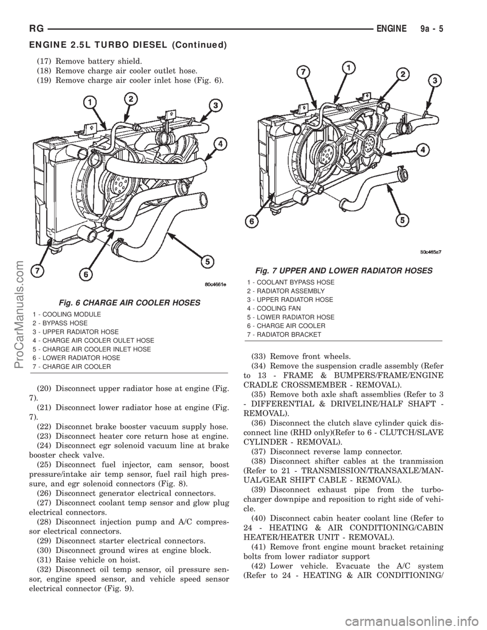
(17) Remove battery shield.
(18) Remove charge air cooler outlet hose.
(19) Remove charge air cooler inlet hose (Fig. 6).
(20) Disconnect upper radiator hose at engine (Fig.
7).
(21) Disconnect lower radiator hose at engine (Fig.
7).
(22) Disconnet brake booster vacuum supply hose.
(23) Disconnect heater core return hose at engine.
(24) Disconnect egr solenoid vacuum line at brake
booster check valve.
(25) Disconnect fuel injector, cam sensor, boost
pressure/intake air temp sensor, fuel rail high pres-
sure, and egr solenoid connectors (Fig. 8).
(26) Disconnect generator electrical connectors.
(27) Disconnect coolant temp sensor and glow plug
electrical connectors.
(28) Disconnect injection pump and A/C compres-
sor electrical connectors.
(29) Disconnect starter electrical connectors.
(30) Disconnect ground wires at engine block.
(31) Raise vehicle on hoist.
(32) Disconnect oil temp sensor, oil pressure sen-
sor, engine speed sensor, and vehicle speed sensor
electrical connector (Fig. 9).(33) Remove front wheels.
(34) Remove the suspension cradle assembly (Refer
to 13 - FRAME & BUMPERS/FRAME/ENGINE
CRADLE CROSSMEMBER - REMOVAL).
(35) Remove both axle shaft assemblies (Refer to 3
- DIFFERENTIAL & DRIVELINE/HALF SHAFT -
REMOVAL).
(36) Disconnect the clutch slave cylinder quick dis-
connect line (RHD only)(Refer to 6 - CLUTCH/SLAVE
CYLINDER - REMOVAL).
(37) Disconnect reverse lamp connector.
(38) Disconnect shifter cables at the tranmission
(Refer to 21 - TRANSMISSION/TRANSAXLE/MAN-
UAL/GEAR SHIFT CABLE - REMOVAL).
(39) Disconnect exhaust pipe from the turbo-
charger downpipe and reposition to right side of vehi-
cle.
(40) Disconnect cabin heater coolant line (Refer to
24 - HEATING & AIR CONDITIONING/CABIN
HEATER/HEATER UNIT - REMOVAL).
(41) Remove front engine mount bracket retaining
bolts from lower radiator support
(42) Lower vehicle. Evacuate the A/C system
(Refer to 24 - HEATING & AIR CONDITIONING/
Fig. 6 CHARGE AIR COOLER HOSES
1 - COOLING MODULE
2 - BYPASS HOSE
3 - UPPER RADIATOR HOSE
4 - CHARGE AIR COOLER OULET HOSE
5 - CHARGE AIR COOLER INLET HOSE
6 - LOWER RADIATOR HOSE
7 - CHARGE AIR COOLER
Fig. 7 UPPER AND LOWER RADIATOR HOSES
1 - COOLANT BYPASS HOSE
2 - RADIATOR ASSEMBLY
3 - UPPER RADIATOR HOSE
4 - COOLING FAN
5 - LOWER RADIATOR HOSE
6 - CHARGE AIR COOLER
7 - RADIATOR BRACKET
RGENGINE9a-5
ENGINE 2.5L TURBO DIESEL (Continued)
ProCarManuals.com
Page 1367 of 2399
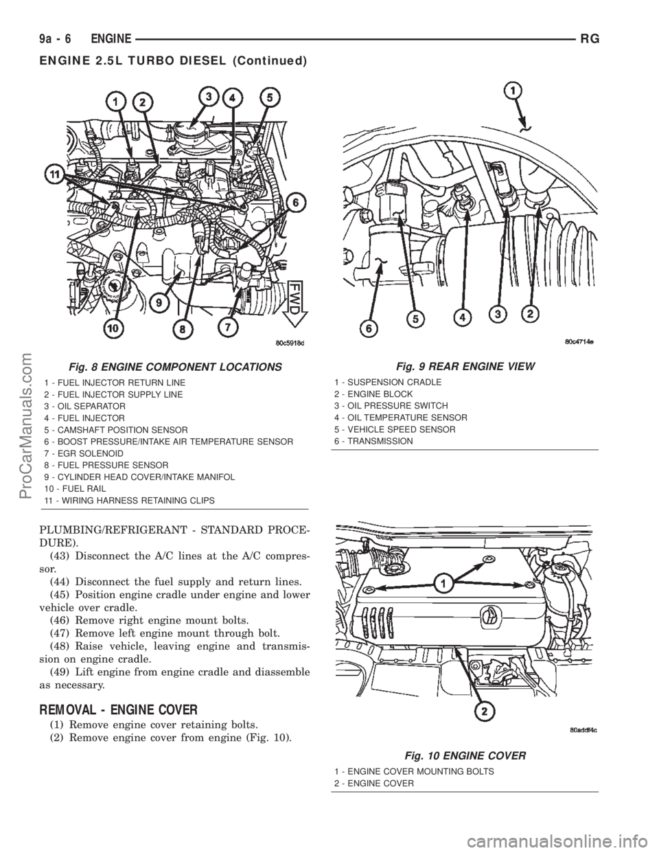
PLUMBING/REFRIGERANT - STANDARD PROCE-
DURE).
(43) Disconnect the A/C lines at the A/C compres-
sor.
(44) Disconnect the fuel supply and return lines.
(45) Position engine cradle under engine and lower
vehicle over cradle.
(46) Remove right engine mount bolts.
(47) Remove left engine mount through bolt.
(48) Raise vehicle, leaving engine and transmis-
sion on engine cradle.
(49) Lift engine from engine cradle and diassemble
as necessary.
REMOVAL - ENGINE COVER
(1) Remove engine cover retaining bolts.
(2) Remove engine cover from engine (Fig. 10).
Fig. 8 ENGINE COMPONENT LOCATIONS
1 - FUEL INJECTOR RETURN LINE
2 - FUEL INJECTOR SUPPLY LINE
3 - OIL SEPARATOR
4 - FUEL INJECTOR
5 - CAMSHAFT POSITION SENSOR
6 - BOOST PRESSURE/INTAKE AIR TEMPERATURE SENSOR
7 - EGR SOLENOID
8 - FUEL PRESSURE SENSOR
9 - CYLINDER HEAD COVER/INTAKE MANIFOL
10 - FUEL RAIL
11 - WIRING HARNESS RETAINING CLIPS
Fig. 9 REAR ENGINE VIEW
1 - SUSPENSION CRADLE
2 - ENGINE BLOCK
3 - OIL PRESSURE SWITCH
4 - OIL TEMPERATURE SENSOR
5 - VEHICLE SPEED SENSOR
6 - TRANSMISSION
Fig. 10 ENGINE COVER
1 - ENGINE COVER MOUNTING BOLTS
2 - ENGINE COVER
9a - 6 ENGINERG
ENGINE 2.5L TURBO DIESEL (Continued)
ProCarManuals.com
Page 1368 of 2399
INSTALLATION
INSTALLATION - 2.5L TURBO DIESEL ENGINE
(1) Reassembly engine and transmission assembly
and install on engine cradle.
(2) Position engine and cradle assembly under
vehicle.
(3) Slowly lower the vehicle down over the engine
and cradle assembly.
(4) Install right engine mount bolts. Torque to
54N´m (40 ft. lbs.)
(5) Install left engine mount through bolt. Torque
to 75N´m (55 ft. lbs.)
(6) Raise vehicle and engine from engine cradle.
(7) Attach front engine mount bracket to lower
radiator support. Torque to 54N´m (40 ft. lbs.)
(8) Connect cabin heater coolant hose.
(9) Connect exhaust pipe to the turbocharger
downpipe flange. Torque to 28 N´m (250 in. lbs.)
(10) Connect reverse lamp electrical connector at
transmission.
(11) Connect both shifter cables (Refer to 21 -
TRANSMISSION/TRANSAXLE/MANUAL/GEAR
SHIFT CABLE - INSTALLATION).
(12) Connect the clutch slave cylinder quick dis-
connect connector (RHD only)(Refer to 6 - CLUTCH/
SLAVE CYLINDER - INSTALLATION).
(13) Install engine harness into bracket on trans-
mission.
(14) Lower vehicle.
(15) Connect fuel supply and return lines.
(16) Connect A/C lines to A/C compressor. Torque
to 23N´m (17 ft. lbs.)
(17) Route engine wiring harnes to proper location.
(18) Connect engine harness ground cables to
engine block
(19) Connect starter solenoid electrical connector
and battery feed wire to starter. Torque to 10N´m (90
in. lbs.)
(20) Connect A/C compressor, injection pump, glow
plugs, and coolant temperature sensor electrical con-
nectors.
(21) Connect generator electrical connector. Torque
to 9N´m (75 in. lbs.)
(22) Connect the fuel injector, fuel pressure sensor,
boost pressure/intake air temp sensor, cam sensor,
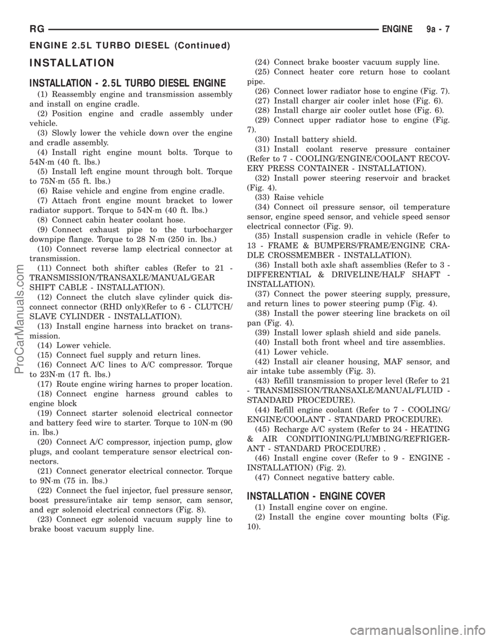
and egr solenoid electrical connectors (Fig. 8).
(23) Connect egr solenoid vacuum supply line to
brake boost vacuum supply line.(24) Connect brake booster vacuum supply line.
(25) Connect heater core return hose to coolant
pipe.
(26) Connect lower radiator hose to engine (Fig. 7).
(27) Install charger air cooler inlet hose (Fig. 6).
(28) Install charge air cooler outlet hose (Fig. 6).
(29) Connect upper radiator hose to engine (Fig.
7).
(30) Install battery shield.
(31) Install coolant reserve pressure container
(Refer to 7 - COOLING/ENGINE/COOLANT RECOV-
ERY PRESS CONTAINER - INSTALLATION).
(32) Install power steering reservoir and bracket
(Fig. 4).
(33) Raise vehicle
(34) Connect oil pressure sensor, oil temperature
sensor, engine speed sensor, and vehicle speed sensor
electrical connector (Fig. 9).
(35) Install suspension cradle in vehicle (Refer to
13 - FRAME & BUMPERS/FRAME/ENGINE CRA-
DLE CROSSMEMBER - INSTALLATION).
(36) Install both axle shaft assemblies (Refer to 3 -
DIFFERENTIAL & DRIVELINE/HALF SHAFT -
INSTALLATION).
(37) Connect the power steering supply, pressure,
and return lines to power steering pump (Fig. 4).
(38) Install the power steering line brackets on oil
pan (Fig. 4).
(39) Install lower splash shield and side panels.
(40) Install both front wheel and tire assemblies.
(41) Lower vehicle.
(42) Install air cleaner housing, MAF sensor, and
air intake tube assembly (Fig. 3).
(43) Refill transmission to proper level (Refer to 21
- TRANSMISSION/TRANSAXLE/MANUAL/FLUID -
STANDARD PROCEDURE).
(44) Refill engine coolant (Refer to 7 - COOLING/
ENGINE/COOLANT - STANDARD PROCEDURE).
(45) Recharge A/C system (Refer to 24 - HEATING
& AIR CONDITIONING/PLUMBING/REFRIGER-
ANT - STANDARD PROCEDURE) .
(46) Install engine cover (Refer to 9 - ENGINE -
INSTALLATION) (Fig. 2).
(47) Connect negative battery cable.
INSTALLATION - ENGINE COVER
(1) Install engine cover on engine.
(2) Install the engine cover mounting bolts (Fig.
10).
RGENGINE9a-7
ENGINE 2.5L TURBO DIESEL (Continued)
ProCarManuals.com
Page 1409 of 2399
(3) Install oil pump retaining bolts (Fig. 71).
Torque bolts to 10.8N´m.
(4) Install crankshaft sprocket (Fig. 71). Torque
bolts to 10.8N´m.
(5) Install front engine cover (Refer to 9 -
ENGINE/ENGINE BLOCK/ENGINE COVER -
INSTALLATION).
(6) Install timing belt inner cover (Refer to 9 -
ENGINE/VALVE TIMING/TIMING BELT / CHAIN
COVER(S) - INSTALLATION).
(7) Install timing belt (Refer to 9 - ENGINE/
VALVE TIMING/TIMING BELT/CHAIN AND
SPROCKETS - INSTALLATION) .
(8) Install timing belt outer cover (Refer to 9 -
ENGINE/VALVE TIMING/TIMING BELT / CHAIN
COVER(S) - INSTALLATION).
(9) Install accessory drive belt (Refer to 7 - COOL-
ING/ACCESSORY DRIVE/DRIVE BELTS - INSTAL-
LATION).
(10) Install power steering belt (Refer to 7 -
COOLING/ACCESSORY DRIVE/DRIVE BELTS -
INSTALLATION).
(11) Connect negative battery cable.
INSTALLATION
(1) Lubricate o-ring on oil pump pickup tube with
engine oil.
(2) Install pickup tube in engine block and install
retaining bolt (Fig. 72). Torque bolt to 32.4N´m.
(3) Install oil pan (Refer to 9 - ENGINE/LUBRI-
CATION/OIL PAN - INSTALLATION).
(4) Refill engine oil to proper level.
(5) Connect negative battery cable.
OIL PRESSURE SENSOR/
SWITCH
DESCRIPTION
The oil pressure switch is located on the right side
of the engine block. The switch screws into the
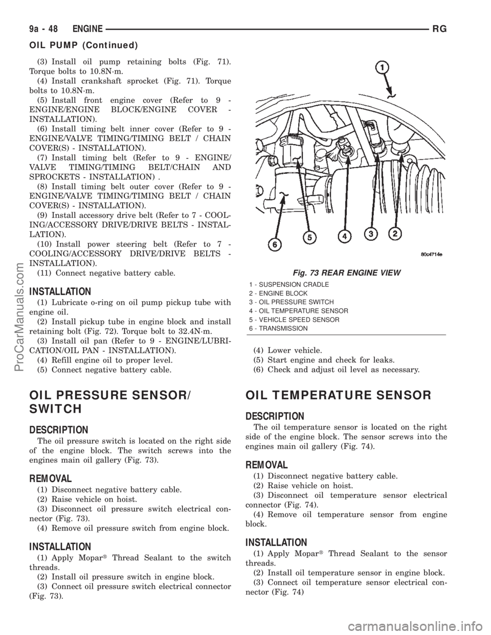
engines main oil gallery (Fig. 73).
REMOVAL
(1) Disconnect negative battery cable.
(2) Raise vehicle on hoist.
(3) Disconnect oil pressure switch electrical con-
nector (Fig. 73).
(4) Remove oil pressure switch from engine block.
INSTALLATION
(1) Apply MopartThread Sealant to the switch
threads.
(2) Install oil pressure switch in engine block.
(3) Connect oil pressure switch electrical connector
(Fig. 73).(4) Lower vehicle.
(5) Start engine and check for leaks.
(6) Check and adjust oil level as necessary.
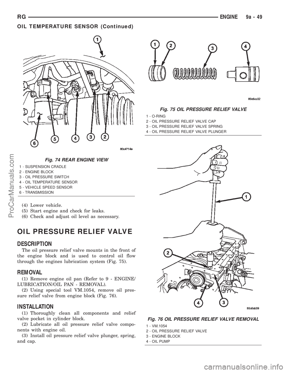
OIL TEMPERATURE SENSOR
DESCRIPTION
The oil temperature sensor is located on the right
side of the engine block. The sensor screws into the
engines main oil gallery (Fig. 74).
REMOVAL
(1) Disconnect negative battery cable.
(2) Raise vehicle on hoist.
(3) Disconnect oil temperature sensor electrical
connector (Fig. 74).
(4) Remove oil temperature sensor from engine
block.
INSTALLATION
(1) Apply MopartThread Sealant to the sensor
threads.
(2) Install oil temperature sensor in engine block.
(3) Connect oil temperature sensor electrical con-
nector (Fig. 74)
Fig. 73 REAR ENGINE VIEW
1 - SUSPENSION CRADLE
2 - ENGINE BLOCK
3 - OIL PRESSURE SWITCH
4 - OIL TEMPERATURE SENSOR
5 - VEHICLE SPEED SENSOR
6 - TRANSMISSION
9a - 48 ENGINERG
OIL PUMP (Continued)
ProCarManuals.com
Page 1410 of 2399
(4) Lower vehicle.
(5) Start engine and check for leaks.
(6) Check and adjust oil level as necessary.
OIL PRESSURE RELIEF VALVE
DESCRIPTION
The oil pressure relief valve mounts in the front of
the engine block and is used to control oil flow
through the engines lubrication system (Fig. 75).
REMOVAL
(1) Remove engine oil pan (Refer to 9 - ENGINE/
LUBRICATION/OIL PAN - REMOVAL).
(2) Using special tool VM.1054, remove oil pres-
sure relief valve from engine block (Fig. 76).
INSTALLATION
(1) Thoroughly clean all components and relief
valve pocket in cylinder block.
(2) Lubricate all oil pressure relief valve compo-
nents with engine oil.
(3) Install oil pressure relief valve plunger, spring,
and cap.
Fig. 74 REAR ENGINE VIEW
1 - SUSPENSION CRADLE
2 - ENGINE BLOCK
3 - OIL PRESSURE SWITCH
4 - OIL TEMPERATURE SENSOR
5 - VEHICLE SPEED SENSOR
6 - TRANSMISSION
Fig. 75 OIL PRESSURE RELIEF VALVE
1 - O-RING
2 - OIL PRESSURE RELIEF VALVE CAP
3 - OIL PRESSURE RELIEF VALVE SPRING
4 - OIL PRESSURE RELIEF VALVE PLUNGER
Fig. 76 OIL PRESSURE RELIEF VALVE REMOVAL
1 - VM.1054
2 - OIL PRESSURE RELIEF VALVE
3 - ENGINE BLOCK
4 - OIL PUMP
RGENGINE9a-49
OIL TEMPERATURE SENSOR (Continued)
ProCarManuals.com