Page 168 of 486

2-60 Turn and Lane-Change Signals
The turn signal has two upward (for right) and two
downward (for left) positions. These positions allow you
to signal a turn or a lane change.
To signal a turn, move the lever all the way up or down.
When the turn is finished, the lever will return automatically.
An arrow on the instrument
panel cluster will flash in
the direction of the turn or
lane change.
To signal a lane change, just raise or lower the lever
until the arrow starts to flash. Hold it there until you
complete your lane change. The lever will return by
itself when you release it.As you signal a turn or a lane change, if the arrow
flashes faster than normal, a signal bulb may be burned
out and other drivers won't see your turn signal.
If a bulb is burned out, replace it to help avoid an
accident. If the arrows don't go on at all when you
signal a turn, check for burned
-out bulbs and check the
fuse. See ªBulb Replacementº and ªFuses and Circuit
Breakersº in the Index.
If you have a trailer towing option with added wiring for
the trailer lamps, the signal indicator will flash at a
normal rate even if a turn signal bulb is burned out.
Check the front and rear turn signal lamps regularly to
make sure they are working.
Turn Signal on Chime
If either turn signal is left on for more than 3/4 mile
(1.2 km), a chime will sound to let the driver know to
turn it off.
If you need to leave the signal on for more than 3/4 mile
(1.2 km), turn off the signal and then turn it back on.
Page 169 of 486

2-61
Headlamp High/Low-Beam Changer
To change the headlamps from high to low beam, or low
to high, simply pull the turn signal lever all the way
toward you. Then release it.
When the high beams
are on, this light on the
instrument panel cluster
will also be on.
Your fog lamps will turn off when you switch to high
beams. Using your high beams in fog is not recommended.
Flash-to-Pass Feature
When the headlamps are off, pull the lever toward you
to momentarily switch on the high beams (to signal that
you are going to pass). When you release the lever, they
will turn off.
Windshield Wipers
To operate the windshield wipers turn the band
marked WIPER, located on the multifunction lever,
upward or downward.MIST: Turn the band to MIST for a single wiping cycle.
Hold it there until the wipers start. Then let go. The
wipers will stop after one wipe. If you want more wipes,
hold the band on mist longer.
OFF: Turn the band to OFF to turn off the
windshield wipers.
LOW: Turn the band to LOW, for steady wiping at
low speed.
HIGH: Turn the band to HIGH, for steady wiping at
high speed.
DELAY: Turn the band away from you to one of the
five sensitivity settings between OFF and LOW, to
choose the delayed wiping cycle. The further the band is
turned toward LOW, the shorter the delay will be. Use
this setting for light rain or snow.
Remember that damaged wiper blades may prevent you
from seeing well enough to drive safely. To avoid
damage, be sure to clear ice and snow from the wiper
blades before using them. If they're frozen to the
windshield, carefully loosen or thaw them. If your
blades do become damaged, get new blades or
blade inserts.
Heavy snow or ice can overload your wipers. A circuit
breaker will stop them until the motor cools. Clear away
snow or ice to prevent an overload.
Page 207 of 486
2-99
The main components of the instrument panel are the following:
A. Side Vents
B. Front Vents
C. Turn Signal/Multifunction Lever
D. Hazard Warning Flasher Switch
E. Instrument Panel Cluster
F. Center Vents
G. Audio System
H. Side Vents
I. Exterior Lamps Control
J. Hood Release
K. HornL. Ignition Switch
M. Climate Controls
N. Rear Fan Controls (Option)
O. Cupholder Tray
P. Accessory Power Outlet
Q. Storage Bin
R. Instrument Panel Switchbank
S. Glove Box
T. Front Vents
U. Instrument Panel Fuse Block
Page 208 of 486
2-100 Instrument Panel Cluster
Your instrument panel cluster is designed to let you know at a glance how your vehicle is running. You'll know how
fast you're going, how much fuel you're using, and many other things you'll need to drive safely and economically.
The indicator warning lights and gages are explained on the following pages.
United States version shown, Canada similar
Page 220 of 486

2-112
Here are four things that some owners ask about. All
these things are normal and do not indicate that anything
is wrong with the fuel gage.
�At the gas station, the gas pump shuts off before the
gage reads full.
�It takes a little more (or less) fuel to fill up than the
gage reads. For example, the gage reads half full, but
it took more (or less) than half of the tank's capacity
to fill it.
�The gage pointer may move while cornering, braking
or speeding up.
�The gage may not indicate empty when the ignition
is turned off.
Message Center
The message center is located in the instrument
panel cluster. It gives you important safety and
maintenance facts.
Charging System Indicator Message
The charging system
battery symbol will come
on in the message center
when you turn on the
ignition as a check to
show you it is working.
It will remain on as long as the engine is not running. It
should go out once the engine is running. If it stays on,
or comes on while you are driving, you may have a
problem with the charging system. It could indicate that
you have problems with a generator drive belt, or
another electrical problem. Have it checked right away.
Driving while this indicator appears in the message
center could drain your battery.
If you must drive a short distance with the message on,
be certain to turn off all your accessories, such as the
radio and air conditioner.
Page 342 of 486

5-9
To disconnect the jumper cables from both vehicles, do
the following:
1. Disconnect the black negative (
-) cable from the
vehicle that had the dead battery.
2. Disconnect the black negative (
-) cable from the
vehicle with the good battery.
3. Disconnect the red positive (+) cable from the
vehicle with the good battery.
4. Disconnect the red positive (+) cable from the
other vehicle.
5. Return the red positive (+) remote terminal cover to
its original position.
Towing Your Vehicle
Consult your dealer or a professional towing service if
you need to have your disabled vehicle towed. See
ªRoadside Assistanceº in the Index. If you want to tow
your vehicle behind another vehicle for recreational
purposes (such as behind a motorhome), see
ªRecreational Vehicle Towingº in the Index.
Engine Overheating
You will find an engine coolant temperature gage on the
instrument panel cluster. See ªEngine Coolant
Temperature Gageº in the Index. You also have anengine coolant temperature warning message on the
instrument panel cluster. See ªEngine Coolant
Temperature Warning Messageº in the Index.
Overheated Engine Protection
Operating Mode
This emergency operating mode allows your vehicle to
be driven to a safe place in an emergency situation.
If an overheated engine condition exists, an overheat
protection mode which alternates firing groups of
cylinders helps prevent engine damage. In this mode,
you will notice a significant loss in power and engine
performance. The temperature gage will indicate an
overheat condition exists. Driving extended miles (km)
and/or towing a trailer in the overheat protection mode
should be avoided.
NOTICE:
After driving in the overheated engine protection
operating mode, to avoid engine damage, allow
the engine to cool before attempting any repair.
The engine oil will be severely degraded. Repair
the cause of coolant loss, change the oil and reset
the oil life system. See ªEngine Oilº in the Index.
Page 384 of 486

6-12
Engine Oil
United States Canada
If the low engine oil level message appears on the
instrument cluster, it means you need to check your
engine oil level right away. For more information, see
ªLow Engine Oil Level Messageº in the Index.
You should check your engine oil level regularly; this is
an added reminder.
Checking Engine Oil
It's a good idea to check your engine oil every time you
get fuel. In order to get an accurate reading, the oil must
be warm and the vehicle must be on level ground.
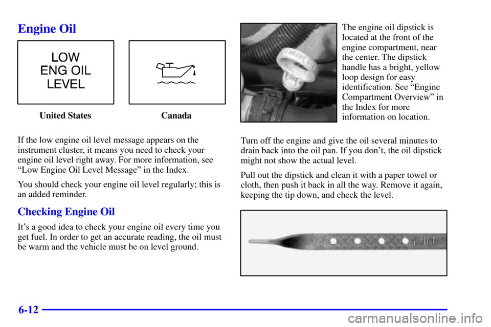
The engine oil dipstick is
located at the front of the
engine compartment, near
the center. The dipstick
handle has a bright, yellow
loop design for easy
identification. See ªEngine
Compartment Overviewº in
the Index for more
information on location.
Turn off the engine and give the oil several minutes to
drain back into the oil pan. If you don't, the oil dipstick
might not show the actual level.
Pull out the dipstick and clean it with a paper towel or
cloth, then push it back in all the way. Remove it again,
keeping the tip down, and check the level.
Page 438 of 486
6-66
Circuit Breakers Usage
HEADLAMP Daytime Running Lamps (DRL)
Control Module, Headlamp and
Instrument Panel Dimmer Switch
PWR SLD DR Power Sliding Door
PWR WDO Front Power WindowsCircuit Breakers Usage
PWR/HEATED
SEAT PSDSix
-Way Power Seats and Rear
Side Door Actuator Motor
FRT HVAC
HI BLWRBlower Motor Hi Speed
Relay Module
Fuses Usage
SWC
BACKLIGHTSteering Wheel Radio Control
Switches (Illumination)
PCM/PASS
KEY/CLUSTERInstrument Cluster to
PRNDL Indicators
PWR MIRROR Power Remote Control
Mirror Switch
CRUISE Cruise Control Module, Switch
and Release Switch
Blank Not Used
PCM/CRANK Powertrain Control Module
(PCM), Ignition Crank
PASS KEY PASS
-Key� III System