2002 BMW X5 engine
[x] Cancel search: enginePage 35 of 48

35
M54engMS43/ST036/6/20000
The dual VANOS in conjunction with the variable intake manifold provides an additional
emission control feature.
Because of the improved combustion, the camshaft timing is adjusted for more overlap.
The increased overlap supports internal exhaust gas recirculation (EGR) which reduces
tailpipe emissions and lowers fuel consumption.
During the part load engine range, the intake camshaft overlap opens the intake valve. This
allows limited exhaust gas reflow the intake manifold.
The “internal” EGR reduces the cylinder temperature thus lowering NOx. This feature pro-
vides EGR without the external hardware as seen on previous systems.
INLET
TURBULENCE
IDLE AIR
CONTROL VALVEMDK
INT. EGR
CATALYST
CLOSE TO
ENGINESECONDARY
AIR
INJECTION
(AIR FILTER)OUTLET-VANOS
(228/80-105)INLET-VANOS
(228/80-120)
Page 36 of 48
36
M54engMS43/ST036/6/2000
ELECTRIC FAN
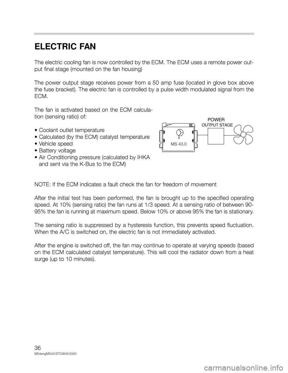
The electric cooling fan is now controlled by the ECM. The ECM uses a remote power out-
put final stage (mounted on the fan housing)
The power output stage receives power from a 50 amp fuse (located in glove box above
the fuse bracket). The electric fan is controlled by a pulse width modulated signal from the
ECM.
The fan is activated based on the ECM calcula-
tion (sensing ratio) of:
• Coolant outlet temperature
• Calculated (by the ECM) catalyst temperature
• Vehicle speed
• Battery voltage
• Air Conditioning pressure (calculated by IHKA
and sent via the K-Bus to the ECM)
NOTE: If the ECM indicates a fault check the fan for freedom of movement
After the initial test has been performed, the fan is brought up to the specified operating
speed. At 10% (sensing ratio) the fan runs at 1/3 speed. At a sensing ratio of between 90-
95% the fan is running at maximum speed. Below 10% or above 95% the fan is stationary.
The sensing ratio is suppressed by a hysteresis function, this prevents speed fluctuation.
When the A/C is switched on, the electric fan is not immediately activated.
After the engine is switched off, the fan may continue to operate at varying speeds (based
on the ECM calculated catalyst temperature). This will cool the radiator down from a heat
surge (up to 10 minutes).
OUTPUT STAGE
MS42.0
POWER
MS 43.0
Page 37 of 48
37
M54engMS43/ST036/6/20000
SECONDARY AIR INJECTION
This ECM controlled function remains unchanged from
the previous Siemens MS system, however there is a
hardware change.
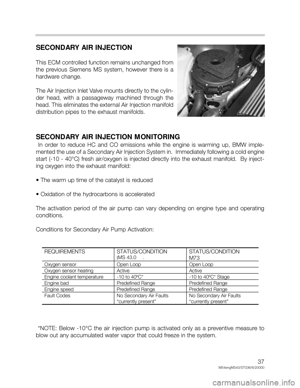
The Air Injection Inlet Valve mounts directly to the cylin-
der head, with a passageway machined through the
head. This eliminates the external Air Injection manifold
distribution pipes to the exhaust manifolds.
SECONDARY AIR INJECTION MONITORING
In order to reduce HC and CO emissions while the engine is warming up, BMW imple-
mented the use of a Secondary Air Injection System in. Immediately following a cold engine
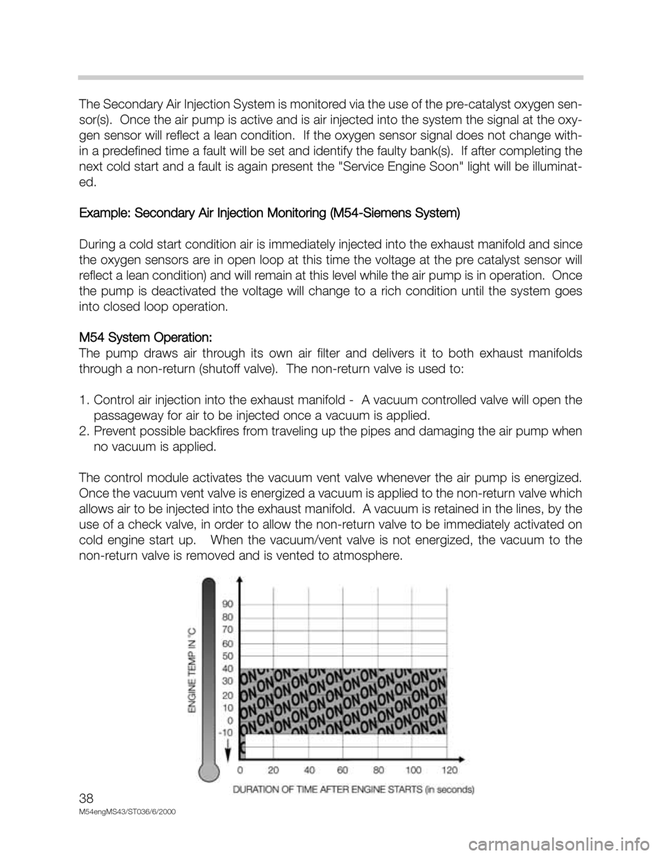
start (-10 - 40°C) fresh air/oxygen is injected directly into the exhaust manifold. By inject-
ing oxygen into the exhaust manifold:
• The warm up time of the catalyst is reduced
• Oxidation of the hydrocarbons is accelerated
The activation period of the air pump can vary depending on engine type and operating
conditions.
Conditions for Secondary Air Pump Activation:
*NOTE: Below -10°C the air injection pump is activated only as a preventive measure to
blow out any accumulated water vapor that could freeze in the system.
REQUIREMENTS STATUS/CONDITION
M52 & M44STATUS/CONDITION
M73
Oxygen sensor Open Loop Open Loop
Oxygen sensor heating Active Active
Engine coolant temperature -10 to 40ºC* -10 to 40ºC* Stage
Engine bad Predefined Range Predefined Range
Engine speed Predefined Range Predefined Range
Fault Codes No Secondary Air Faults
“currently present”
No Secondary Air Faults
“currently present”
MS 43.0
Page 38 of 48
38
M54engMS43/ST036/6/2000
The Secondary Air Injection System is monitored via the use of the pre-catalyst oxygen sen-
sor(s). Once the air pump is active and is air injected into the system the signal at the oxy-
gen sensor will reflect a lean condition. If the oxygen sensor signal does not change with-
in a predefined time a fault will be set and identify the faulty bank(s). If after completing the
next cold start and a fault is again present the "Service Engine Soon" light will be illuminat-
ed.
Example: Secondary Air Injection Monitoring (M54-Siemens System)
During a cold start condition air is immediately injected into the exhaust manifold and since
the oxygen sensors are in open loop at this time the voltage at the pre catalyst sensor will
reflect a lean condition) and will remain at this level while the air pump is in operation. Once
the pump is deactivated the voltage will change to a rich condition until the system goes
into closed loop operation.
M54 System Operation:
The pump draws air through its own air filter and delivers it to both exhaust manifolds
through a non-return (shutoff valve). The non-return valve is used to:
1. Control air injection into the exhaust manifold - A vacuum controlled valve will open the
passageway for air to be injected once a vacuum is applied.
2. Prevent possible backfires from traveling up the pipes and damaging the air pump when
no vacuum is applied.
The control module activates the vacuum vent valve whenever the air pump is energized.
Once the vacuum vent valve is energized a vacuum is applied to the non-return valve which
allows air to be injected into the exhaust manifold. A vacuum is retained in the lines, by the
use of a check valve, in order to allow the non-return valve to be immediately activated on
cold engine start up. When the vacuum/vent valve is not energized, the vacuum to the
non-return valve is removed and is vented to atmosphere.
Page 39 of 48

39
M54engMS43/ST036/6/20000
ENGINE/VEHICLE SPEED
LIMITATION
For engine/vehicle speed limitation, the ECM will deactivate injection for individual cylinders,
allowing a smoother limitation transition. This prevents over-rev when the engine reaches
maximum RPM (under acceleration), and limits top vehicle speed (approx. 128 mph).
________________________________________________________________
________________________________________________________________
________________________________________________________________
________________________________________________________________
________________________________________________________________
MS 43.0DSC
Page 40 of 48

40
M54engMS43/ST036/6/2000
RZV IGNITION SYSTEM
The Siemens MS43.0 system uses a multiple spark ignition function. The purpose of mul-
tiple ignition is:
• Provide clean burning during engine start up and while idling (reducing emissions).
• This function helps to keep the spark plugs clean for longer service life (new BMW
longlife plugs).
Multiple ignition is active up to an engine speed of approximately 1350 RPM (varied with
engine temperature) and up to 20 degrees after TDC.
Multiple ignition is dependent on battery voltage. When the voltage is low, the primary cur-
rent is also lower and a longer period of time is required to build up the magnetic field in the
coil(s).
• Low battery voltage = less multiple ignitions
• High battery voltage = more multiple ignitions
The 240 ohm shunt resistor is still used on the MS43.0 system for detecting secondary igni-
tion faults and diagnostic purposes.
MS 43.0
Page 42 of 48
42
M54engMS43/ST036/6/2000
RESONANCE SYSTEM
The resonance system provides increased engine torque at low RPM, as well as addition-
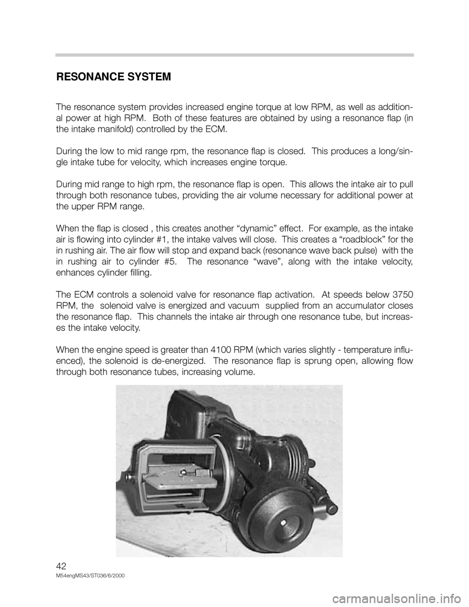
al power at high RPM. Both of these features are obtained by using a resonance flap (in
the intake manifold) controlled by the ECM.
During the low to mid range rpm, the resonance flap is closed. This produces a long/sin-
gle intake tube for velocity, which increases engine torque.
During mid range to high rpm, the resonance flap is open. This allows the intake air to pull
through both resonance tubes, providing the air volume necessary for additional power at
the upper RPM range.
When the flap is closed , this creates another “dynamic” effect. For example, as the intake
air is flowing into cylinder #1, the intake valves will close. This creates a “roadblock” for the
in rushing air. The air flow will stop and expand back (resonance wave back pulse) with the
in rushing air to cylinder #5. The resonance “wave”, along with the intake velocity,
enhances cylinder filling.
The ECM controls a solenoid valve for resonance flap activation. At speeds below 3750
RPM, the solenoid valve is energized and vacuum supplied from an accumulator closes
the resonance flap. This channels the intake air through one resonance tube, but increas-
es the intake velocity.
When the engine speed is greater than 4100 RPM (which varies slightly - temperature influ-
enced), the solenoid is de-energized. The resonance flap is sprung open, allowing flow
through both resonance tubes, increasing volume.
Page 45 of 48
45
M54engMS43/ST036/6/20000
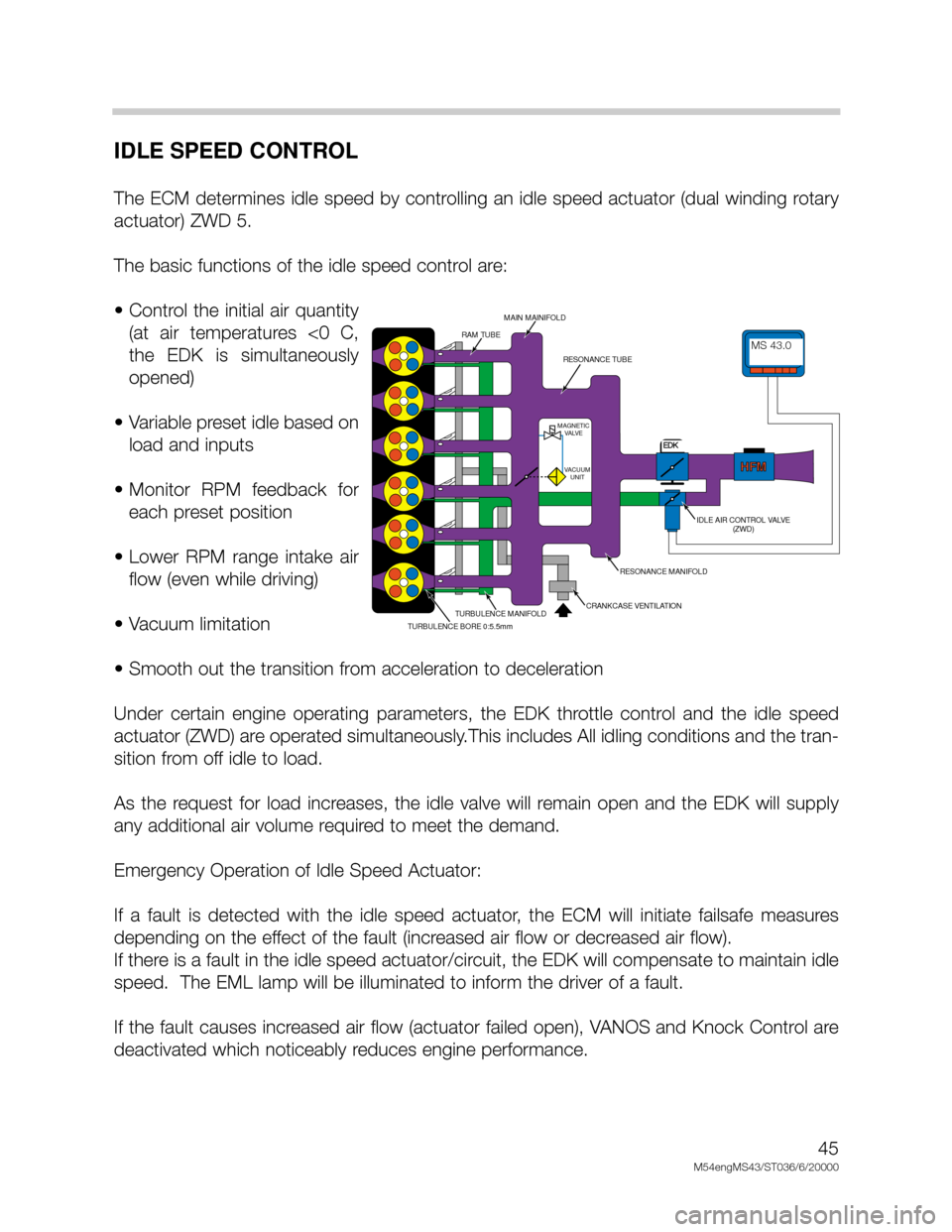
IDLE SPEED CONTROL
The ECM determines idle speed by controlling an idle speed actuator (dual winding rotary
actuator) ZWD 5.
The basic functions of the idle speed control are:
• Control the initial air quantity
(at air temperatures <0 C,
the EDK is simultaneously
opened)
• Variable preset idle based on
load and inputs
• Monitor RPM feedback for
each preset position
• Lower RPM range intake air
flow (even while driving)
• Vacuum limitation
• Smooth out the transition from acceleration to deceleration
Under certain engine operating parameters, the EDK throttle control and the idle speed
actuator (ZWD) are operated simultaneously.This includes All idling conditions and the tran-
sition from off idle to load.
As the request for load increases, the idle valve will remain open and the EDK will supply
any additional air volume required to meet the demand.
Emergency Operation of Idle Speed Actuator:
If a fault is detected with the idle speed actuator, the ECM will initiate failsafe measures
depending on the effect of the fault (increased air flow or decreased air flow).
If there is a fault in the idle speed actuator/circuit, the EDK will compensate to maintain idle
speed. The EML lamp will be illuminated to inform the driver of a fault.
If the fault causes increased air flow (actuator failed open), VANOS and Knock Control are
deactivated which noticeably reduces engine performance.
MDK
HFMHFM
MAGNETIC
VALVE
VACUUM
UNIT
MS42.0MS42.0
RAM TUBE
MAIN MAINIFOLD
RESONANCE TUBE
IDLE AIR CONTROL VALVE
(ZWD)
RESONANCE MANIFOLD
CRANKCASE VENTILATIONTURBULENCE MANIFOLD
TURBULENCE BORE 0:5.5mm
MS 43.0
EDK