2002 BMW X5 secondary air
[x] Cancel search: secondary airPage 1 of 48

Initial Print Date: 02/2000Revision Date: 6/2000
Subject Page
M54 Engine
Introduction . . . . . . . . . . . . . . . . . . . . . . . . . . . . . . . . . . . . . . . . . . . . . . . . . 2
Mechanical changes . . . . . . . . . . . . . . . . . . . . . . . . . . . . . . . . . . . . . . . . . . . . 4
Performance Charts . . . . . . . . . . . . . . . . . . . . . . . . . . . . . . . . . . . . . . . . . . . . 6
Review Questions. . . . . . . . . . . . . . . . . . . . . . . . . . . . . . . . . . . . . . . . . . . . . . 7
Siemen’s MS 43.0 System
• Introduction . . . . . . . . . . . . . . . . . . . . . . . . . . . . . . . . . . . . . . . . . . . . . . 8
• I - P - O . . . . . . . . . . . . . . . . . . . . . . . . . . . . . . . . . . . . . . . . . . . . . . . . 9
MS 43.0 New functions
• Electronic throttle Control . . . . . . . . . . . . . . . . . . . . . . . . . . . . . . . . . .10
• Accelerator Pedal Sensor (PWG) . . . . . . . . . . . . . . . . . . . . . . . . . . . . .11
• Electronic Throttle Valve (EDK) . . . . . . . . . . . . . . . . . . . . . . . . . . . . . .13
• Main Relay Monitor . . . . . . . . . . . . . . . . . . . . . . . . . . . . . . . . . . . . . . . .15
• Engine Optimized Ignition Key OFF . . . . . . . . . . . . . . . . . . . . . . . . . . . .16
• Diagnosis Module Tank Leakage (DM-TL) . . . . . . . . . . . . . . . . . . . . . . .17
• DM-TL Function . . . . . . . . . . . . . . . . . . . . . . . . . . . . . . . . . . . . . . . . . .18
• DM-TL Test Procedure . . . . . . . . . . . . . . . . . . . . . . . . . . . . . . . . . . . . .20
Carry Over Functions
Inputs
• Oxygen Sensor . . . . . . . . . . . . . . . . . . . . . . . . . . . . . . . . . . . . . . . . . .25
• Camshaft Sensors . . . . . . . . . . . . . . . . . . . . . . . . . . . . . . . . . . . . . . . .26
• Crankshaft Sensor . . . . . . . . . . . . . . . . . . . . . . . . . . . . . . . . . . . . . . . .27
• Misfire Detection . . . . . . . . . . . . . . . . . . . . . . . . . . . . . . . . . . . . . . . . .28
• OBD Fault Codes . . . . . . . . . . . . . . . . . . . . . . . . . . . . . . . . . . . . . . . .30
• Mass Air Meter . . . . . . . . . . . . . . . . . . . . . . . . . . . . . . . . . . . . . . . . . .31
Outputs
• VANOS Control . . . . . . . . . . . . . . . . . . . . . . . . . . . . . . . . . . . . . . . . . .33
• Electric Fan . . . . . . . . . . . . . . . . . . . . . . . . . . . . . . . . . . . . . . . . . . . . .36
• Secondary Air Injection . . . . . . . . . . . . . . . . . . . . . . . . . . . . . . . . . . . .37
• Engine Speed Limit . . . . . . . . . . . . . . . . . . . . . . . . . . . . . . . . . . . . . . .39
• RZV Ignition . . . . . . . . . . . . . . . . . . . . . . . . . . . . . . . . . . . . . . . . . . . .40
• Resonance - Turbulence Manifold . . . . . . . . . . . . . . . . . . . . . . . . . . . .42
• Idle Speed control . . . . . . . . . . . . . . . . . . . . . . . . . . . . . . . . . . . . . . . .45
• Cruise Control . . . . . . . . . . . . . . . . . . . . . . . . . . . . . . . . . . . . . . . . . . .46
• Purge Control . . . . . . . . . . . . . . . . . . . . . . . . . . . . . . . . . . . . . . . . . . . .47
Table of Contents
Page 35 of 48

35
M54engMS43/ST036/6/20000
The dual VANOS in conjunction with the variable intake manifold provides an additional
emission control feature.
Because of the improved combustion, the camshaft timing is adjusted for more overlap.
The increased overlap supports internal exhaust gas recirculation (EGR) which reduces
tailpipe emissions and lowers fuel consumption.
During the part load engine range, the intake camshaft overlap opens the intake valve. This
allows limited exhaust gas reflow the intake manifold.
The “internal” EGR reduces the cylinder temperature thus lowering NOx. This feature pro-
vides EGR without the external hardware as seen on previous systems.
INLET
TURBULENCE
IDLE AIR
CONTROL VALVEMDK
INT. EGR
CATALYST
CLOSE TO
ENGINESECONDARY
AIR
INJECTION
(AIR FILTER)OUTLET-VANOS
(228/80-105)INLET-VANOS
(228/80-120)
Page 37 of 48

37
M54engMS43/ST036/6/20000
SECONDARY AIR INJECTION
This ECM controlled function remains unchanged from
the previous Siemens MS system, however there is a
hardware change.
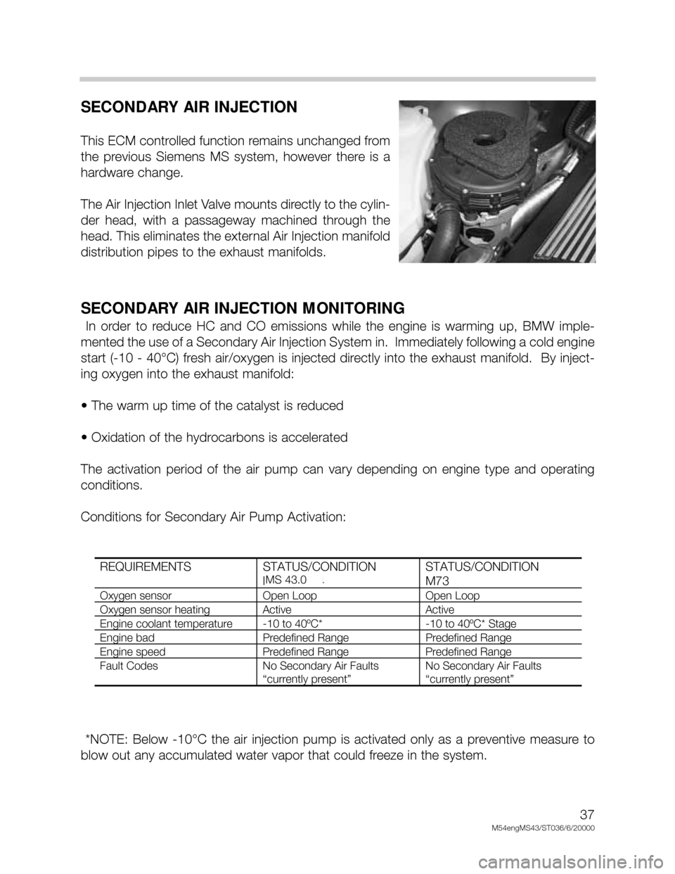
The Air Injection Inlet Valve mounts directly to the cylin-
der head, with a passageway machined through the
head. This eliminates the external Air Injection manifold
distribution pipes to the exhaust manifolds.
SECONDARY AIR INJECTION MONITORING
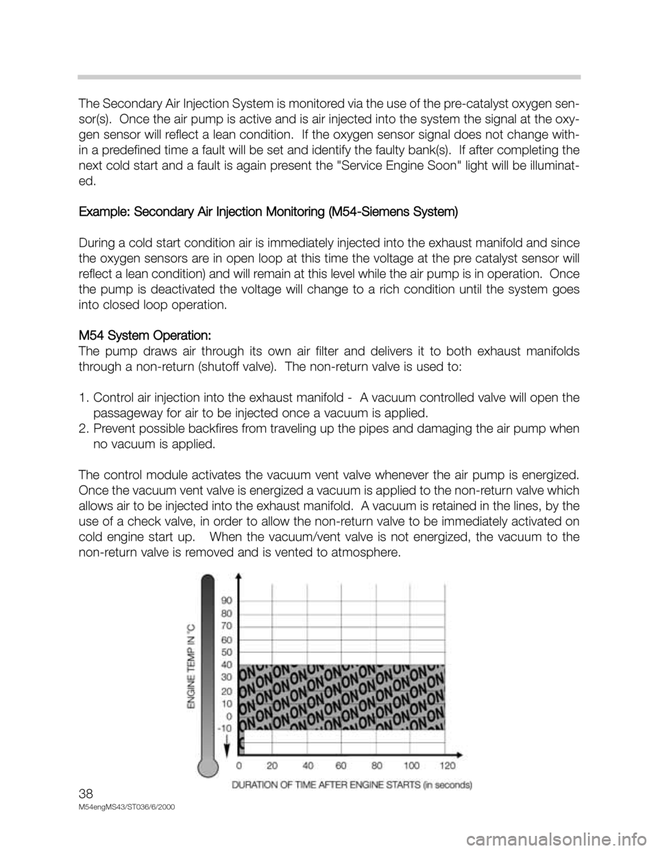
In order to reduce HC and CO emissions while the engine is warming up, BMW imple-
mented the use of a Secondary Air Injection System in. Immediately following a cold engine
start (-10 - 40°C) fresh air/oxygen is injected directly into the exhaust manifold. By inject-
ing oxygen into the exhaust manifold:
• The warm up time of the catalyst is reduced
• Oxidation of the hydrocarbons is accelerated
The activation period of the air pump can vary depending on engine type and operating
conditions.
Conditions for Secondary Air Pump Activation:
*NOTE: Below -10°C the air injection pump is activated only as a preventive measure to
blow out any accumulated water vapor that could freeze in the system.
REQUIREMENTS STATUS/CONDITION
M52 & M44STATUS/CONDITION
M73
Oxygen sensor Open Loop Open Loop
Oxygen sensor heating Active Active
Engine coolant temperature -10 to 40ºC* -10 to 40ºC* Stage
Engine bad Predefined Range Predefined Range
Engine speed Predefined Range Predefined Range
Fault Codes No Secondary Air Faults
“currently present”
No Secondary Air Faults
“currently present”
MS 43.0
Page 38 of 48

38
M54engMS43/ST036/6/2000
The Secondary Air Injection System is monitored via the use of the pre-catalyst oxygen sen-
sor(s). Once the air pump is active and is air injected into the system the signal at the oxy-
gen sensor will reflect a lean condition. If the oxygen sensor signal does not change with-
in a predefined time a fault will be set and identify the faulty bank(s). If after completing the
next cold start and a fault is again present the "Service Engine Soon" light will be illuminat-
ed.
Example: Secondary Air Injection Monitoring (M54-Siemens System)
During a cold start condition air is immediately injected into the exhaust manifold and since
the oxygen sensors are in open loop at this time the voltage at the pre catalyst sensor will
reflect a lean condition) and will remain at this level while the air pump is in operation. Once
the pump is deactivated the voltage will change to a rich condition until the system goes
into closed loop operation.
M54 System Operation:
The pump draws air through its own air filter and delivers it to both exhaust manifolds
through a non-return (shutoff valve). The non-return valve is used to:
1. Control air injection into the exhaust manifold - A vacuum controlled valve will open the
passageway for air to be injected once a vacuum is applied.
2. Prevent possible backfires from traveling up the pipes and damaging the air pump when
no vacuum is applied.
The control module activates the vacuum vent valve whenever the air pump is energized.
Once the vacuum vent valve is energized a vacuum is applied to the non-return valve which
allows air to be injected into the exhaust manifold. A vacuum is retained in the lines, by the
use of a check valve, in order to allow the non-return valve to be immediately activated on
cold engine start up. When the vacuum/vent valve is not energized, the vacuum to the
non-return valve is removed and is vented to atmosphere.