Page 148 of 171
15-07-2002
PRACTICAL INFORMATION141
CHANGING A WHEEL
� Park the vehicle on level, stable and non-slippery ground.
� Apply the handbrake, engage firstor reverse gear (position Pfor the
automatic gearbox) and switch offthe ignition.
Access to the spare wheel and thejack in the boot � Detach the luggage net.
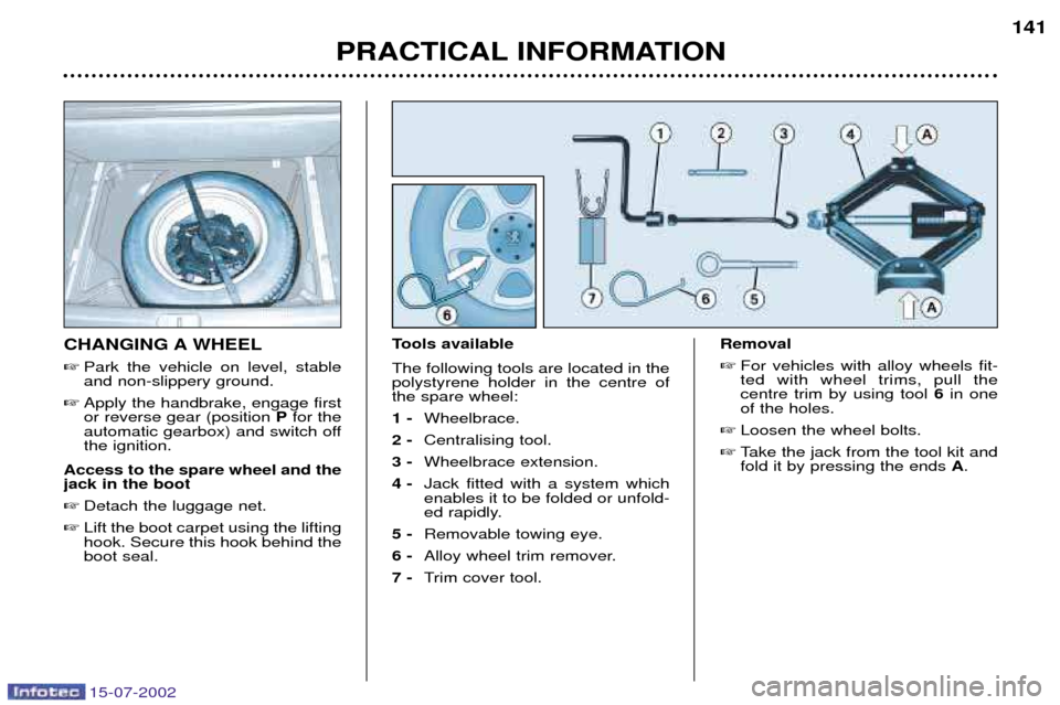
� Lift the boot carpet using the liftinghook. Secure this hook behind theboot seal. Tools available The following tools are located in the polystyrene holder in the centre ofthe spare wheel: 1 -
Wheelbrace.
2 - Centralising tool.
3 - Wheelbrace extension.
4 - Jack fitted with a system which enables it to be folded or unfold-
ed rapidly.
5 - Removable towing eye.
6 - Alloy wheel trim remover.
7 - Trim cover tool. Removal
� For vehicles with alloy wheels fit-ted with wheel trims, pull thecentre trim by using tool 6in one
of the holes.
� Loosen the wheel bolts.
� Take the jack from the tool kit andfold it by pressing the ends A.
Page 149 of 171
.
� Extend")
15-07-2002
PRACTICAL INFORMATION
142
�
Fold the jack by pressing at the ends Aand place it in one of the
four locations Eunderneath the
vehicle (the nearest one to thewheel to be changed).
� Extend the jack, first by hand, pul-ling the ends Athen using wheel-
brace 1and the extension 3.
� Remove a wheel bolt at the topand fit the centralising tool 2in its
place.
� Unscrew the other bolts andremove the wheel.
Fitting a wheel � Position the wheel using the cen-tralising tool to assist you.
� Tighten the bolts by hand andremove the centralising tool. �
Partly tighten the bolts using thewheelbrace.
� Fold the jack and remove it.
� Fully tighten the bolts using thewheelbrace.
� Replace the wheel trim.
� Put the tool holder back in posi-
tion. This helps to keep the bootfloor in its correct position, to pre-vent any deformation of the floorwhen loaded.
Tighten the spare wheel securingstrap to prevent noise and for yoursafety in the event of impact. For your safety, alwayschange the wheel:
Ð on level, stable, non-slippery ground,
Ð with the handbrake applied,
Ð with first or reverse gear engaged (position Pfor the
automatic gearbox),
Ð Never go underneath a vehicle which is supported only by a jack (use a ramp).
After changing the wheel:
Ð have the tightening of the bolts and the tyre pressure checked by a PEUGEOT dealer as soonas possible.
Ð have the punctured wheel repaired and refit it to the vehi-cle as soon as possible.
Tyres fitted with the Tyre Under-Inflation Detection System. These wheels have a pressure
sensor. Have them repaired by a
PEUGEOT dealer.
Page 150 of 171

15-07-2002
Special features of alloy wheels Bolt coversAlloy wheel bolts are covered by chrome trims. Use tool7to remove the trims before
slackening the bolts. Anti-theft bolts*If your wheels are fitted with an anti- theft bolt (one per wheel), thechrome trim and then the plasticcover must be removed using tool
7,
before unscrewing the bolt using oneof the two anti-theft sockets (whichwere given to you on delivery of yourvehicle along with the duplicate keysand the confidential card) and thewheel brace 1.
Note: make a careful note of the
code number engraved on the head
of the anti-theft socket. This willenable you to obtain duplicate anti-
theft sockets from a Peugeot dealer.
* According to model and destination.
PRACTICAL INFORMATION 143
Fitting the spare wheel If your vehicle is fitted with a steel spare wheel, when fitting it, it is
nor-
mal to notice when tightening the
bolts that the washers do not come
into contact with the rim. The sparewheel is secured by the cone-shapeof each bolt. Fitting snow tyresIf you fit snow tyres mounted on steel wheels to your vehicle, it is essential
to use special bolts available from
your PEUGEOT dealer.
Page 151 of 171

15-07-2002
PRACTICAL INFORMATION
144
CHANGING A BULB Front lights
In the engine compartment, remove the style cover secured by one or two butterfly screws, a plastic retainer clip andtwo screws. Note:
handle the bulbs with a dry cloth.
1 - Dipped beam headlamps: H7-55W or Xenon bulb.
WARNING: RISK OF ELECTROCUTION Xenon bulbs must be replaced by a PEUGEOT
dealer.
2 - Main beam headlamps: H1-55W.
� Turn the protective cover of the faulty bulb a quarterof a turn and remove it.
� Disconnect the connector.
� Press the end of the securing clip to free it. Changethe bulb.
� When fitting the new bulb, ensure that the directionnotches are positioned correctly and the securing
clip is fixed properly. �
Reconnect the connector.
� Refit the protective cover.
The headlamps are fitted with polycarbonate glass with aprotective coating. Do not clean them with a dry or abra-
sive cloth, nor with a detergent or solvent product.
3 - Side lights: W 5 W.
� Pull the socket rearwards, remove the bulb and change it.
4 - Direction indicators: PY 21 W (amber).
� Turn the bulb holder a quarter turn and remove it.
� Change the bulb.
� Refit the style cover.
Front foglamps: H1 - 55 W.
Note: In certain climatic conditions (low temperature,
humidity), condensation on the inside surface of the
headlamp glass is normal ; it disappears a few minutes
after the lights are switched on.
Page 152 of 171
.
2 - Brake lights/side lights: P21/5 W.
� Detach the luggage net.
� Lift the boot carpet with the lifting hook. Sec")
15-07-2002
Rear lights Rear wing lights
1 - Direction indicators: PY 21 W (amber).
2 - Brake lights/side lights: P21/5 W.
� Detach the luggage net.
� Lift the boot carpet with the lifting hook. Secure this hook behindthe boot seal.
� Unclip the lower part of the silltrim, then dislodge it by pullingupwards.
� Remove the plastic retainer clipsecuring the side trim to the
floor. �
Unclip the side trim.
� Remove the two butterfly nutssecuring the light.
� Remove the eyelet.
� Take out the lamp.
� Turn the lamp holder a quarterturn.
� Change the faulty bulb.
� Lock the bulb holder in place.When refitting it, ensure that thelamp is correctly positioned andsecured.
PRACTICAL INFORMATION
145Direction indicator repeaters:
WY 5 W (amber).
� Push the repeater forwards orbackwards and release the
assembly.
� Hold the connector and turn thetransparent cover a quarter turn.
� Change the bulb.
Amber coloured bulbs (direction indicators andside repeaters) must bereplaced with bulbs ofidentical specification and
colour.
Page 153 of 171
.
2 - Brake lights/side lights: P21/5 W.
� Detach the luggage net.
� Lift the boot carpet with the lifting hook. Sec")
15-07-2002
Rear lights Rear wing lights
1 - Direction indicators: PY 21 W (amber).
2 - Brake lights/side lights: P21/5 W.
� Detach the luggage net.
� Lift the boot carpet with the lifting hook. Secure this hook behindthe boot seal.
� Unclip the lower part of the silltrim, then dislodge it by pullingupwards.
� Remove the plastic retainer clipsecuring the side trim to the
floor. �
Unclip the side trim.
� Remove the two butterfly nutssecuring the light.
� Remove the eyelet.
� Take out the lamp.
� Turn the lamp holder a quarterturn.
� Change the faulty bulb.
� Lock the bulb holder in place.When refitting it, ensure that thelamp is correctly positioned andsecured.
PRACTICAL INFORMATION
145Direction indicator repeaters:
WY 5 W (amber).
� Push the repeater forwards orbackwards and release the
assembly.
� Hold the connector and turn thetransparent cover a quarter turn.
� Change the bulb.
Amber coloured bulbs (direction indicators andside repeaters) must bereplaced with bulbs ofidentical specification and
colour.
Page 154 of 171
15-07-2002
146PRACTICAL INFORMATION
Boot lid lights 1 - Reversing lights: P 21 W.
2 - Fog lamps: P 21 W.
� Remove the three plastic retain- er clips securing the cover trim(those nearest to the lamp).
� Move aside the trim. �
Turn the bulb holder a quarterturn.
� Change the faulty bulb. Number plate lights:
W 5 W.
� Remove the transparent coverusing a screwdriver blade.
� Change the faulty bulb.
Page 160 of 171

15-07-2002
PRACTICAL INFORMATION151
CHANGING A WINDSCREEN WIPER BLADE Placing the wiper blades in the maintenance position � Less than one minute after switch-
ing off the ignition, activate thewindscreen wiper stalk to positionthe blades in the centre of thewindscreen (maintenance posi-tion).
Replacing a blade � Lift the arm, then unclip the bladeand remove it.
� Fit the new blade and fold downthe arm.
To park the blades, switch on theignition and operate the wind-screen wiper stalk.
REMOVING A MAT When removing a mat on the driver's or passenger's side, push back theseat as far as possible and removethe clips.
To remove a rear mat, push the cor- responding front seat forward andremove the clip. On refitting, position the mat and press firmly to refit the securing clips.
LOAD REDUCTION When driving, certain functions (heated rear screen, heating systemfor passenger compartment of diesel
vehicles, etc.) may be switched off
temporarily, depending on the levelof battery charge. Reactivation of the functions on standby is automatic, as soon as thebattery permits.
A flat battery prevents the engine from starting.
ECONOMY MODE FUNCTION After the engine has stopped, certain
functions (windscreen wiper, electricwindows, sunroof, rear electric blind,electric seats, audio equipment, tele-phone etc) can only be used for thir-ty minutes, to prevent discharging
the battery.
Once the thirty minutes are over, the message
"Economy mode active"
appears on the multiÐfunction dis-play and the active functions are put
on standby. These functions are automaticallyreactivated next time the vehicle isdriven. Note:
if the telephone is being used
when economy mode starts, it will still be possible to finish the call.