Page 25 of 106

INSTRUMENT AND CONTROL FUNCTIONS
3-8
3
EAU00185
CAUTION:@ Immediately wipe off spilled fuel
with a clean, dry, soft cloth, since
fuel may deteriorate painted surfac-
es or plastic parts. @
EAU00191
NOTE:@ If knocking (or pinging) occurs, use
gasoline of a different brand or with a
higher octane grade. @
EAU02969
Fuel cock The fuel cock supplies fuel from the
tank to the carburetors while also filter-
ing it.
The fuel cock lever positions are ex-
plained as follows and shown in the
illustrations.
OFF
With the fuel cock lever in this position,
fuel will not flow. Always turn the fuel
cock lever to this position when the en-
gine is not running.ON
With the fuel cock lever in this position,
fuel flows to the carburetors. Turn the
fuel cock lever to this position when
starting the engine and riding. Recommended fuel:
Regular unleaded gasoline with a
research octane number of 91 or
higher
Fuel tank capacity:
Total amount:
16 L
Reserve amount:
3 L1. Arrow mark positioned over “OFF”Off position
1. Arrow mark positioned over “ON”Normal position
E_5bn.book Page 8 Wednesday, October 4, 2000 7:51 PM
Page 26 of 106
INSTRUMENT AND CONTROL FUNCTIONS
3-9
3
RES
This indicates reserve. With the fuel
cock lever in this position, the fuel re-
serve is made available. Turn the fuel
cock lever to this position if you run out
of fuel while riding. When this occurs,
refuel as soon as possible and be sure
to turn the fuel cock lever back to “ON”!
EAU03031
Starter (choke) knob Starting a cold engine requires a richer
air-fuel mixture, which is supplied by
the starter (choke).
Move the knob in direction
a to turn on
the starter (choke).
Move the knob in direction
b to turn off
the starter (choke).
ECA00038
CAUTION:_ Do not use the starter (choke) for
more than 3 minutes as the exhaust
pipe may discolor from excessive
heat. In addition, extended use of
the starter (choke) will cause after-
burning. If this occurs, turn off the
starter (choke). _
1. Arrow mark positioned over “RES”Reserve position
1. Starter (choke) knob “ ”
E_5bn.book Page 9 Wednesday, October 4, 2000 7:51 PM
Page 27 of 106
INSTRUMENT AND CONTROL FUNCTIONS
3-10
3
EAU01889
Seats (XVS650)Passenger seat
To remove the passenger seatRemove the nut, and then pull the pas-
senger seat up.To install the passenger seat
Insert the projection on the front of the
passenger seat into the seat holder as
shown, place the seat in the original
position, and then install the nut.Rider seat
To remove the rider seat
1. Remove the passenger seat.
2. Remove the bolts, and then pull
the seat up.
To install the rider seat1. Insert the projection on the front of
the rider seat into the seat holder
as shown, place the seat in the
original position, and then install
the bolts.
2. Install the passenger seat.NOTE:@ Make sure that the seats are properly
secured before riding.@
1. NutXVS650
1. Bolt (´ 2)
2. Seat holder
3. ProjectionXVS650
1. Seat holder
2. ProjectionXVS650
E_5bn.book Page 10 Wednesday, October 4, 2000 7:51 PM
Page 28 of 106
INSTRUMENT AND CONTROL FUNCTIONS
3-11
3
EAU01888
Seats (XVS650A)Passenger seat
To remove the passenger seatRemove the bolt, and then pull the pas-
senger seat up.To install the passenger seat
Insert the projections on the front of the
passenger seat into the holder as
shown, place the seat in the original
position, and then install the bolt.Rider seat
To remove the rider seat
1. Remove the passenger seat.
2. Remove the bolt, and then pull the
rider seat up.
1. BoltXVS650A
1. Seat holder (´ 2)
2. Projection (´ 2)XVS650A
1. BoltXVS650A
E_5bn.book Page 11 Wednesday, October 4, 2000 7:51 PM
Page 29 of 106
INSTRUMENT AND CONTROL FUNCTIONS
3-12
3
To install the rider seat
1. Insert the projection on the front of
the rider seat into the holder as
shown, place the seat in the origi-
nal position, and then install the
bolt.
2. Install the passenger seat.NOTE:_ Make sure that the seats are properly
secured before riding. _
EAU00260
Helmet holder To open the helmet holder, insert the
key into the lock, and then turn the key
as shown.
To lock the helmet holder, place it in
the original position, and then remove
the key.
EW000030
WARNING
@ Never ride with a helmet attached to
the helmet holder, since the helmet
may hit objects, causing loss of
control and possibly an accident. @
1. Seat holder
2. ProjectionXVS650A
1. Helmet holder
2. Unlock.
E_5bn.book Page 12 Wednesday, October 4, 2000 7:51 PM
Page 30 of 106
INSTRUMENT AND CONTROL FUNCTIONS
3-13
3
EAU01869
Storage compartment The storage compartment is located on
the left side of the motorcycle.To open the storage compartment
1. Slide the lock cover open, insert
the key into the lock, and then turn
it clockwise.
2. Pull the storage compartment cov-
er out as shown.To close the storage compartment
1. Place the storage compartment
cover in its original position as
shown.
2. Turn the key counterclockwise, re-
move it, and then close the lock
cover.1. Storage compartment cover
2. Storage compartment lock cover
3. Storage compartment lock
1. Storage compartment
2. Storage compartment cover
E_5bn.book Page 13 Wednesday, October 4, 2000 7:51 PM
Page 31 of 106

INSTRUMENT AND CONTROL FUNCTIONS
3-14
3
EAU00299
Adjusting the shock absorber
assembly This shock absorber assembly is
equipped with a spring preload adjust-
ing ring.
EC000015
CAUTION:@ Never attempt to turn an adjusting
mechanism beyond the maximum
or minimum settings. @Adjust the spring preload as follows.
1. Remove the passenger and rider
seats. (See page 3-10 [XVS650]
or 3-11 [XVS650A] for removal
and installation procedures.)
2. To increase the spring preload
and thereby harden the suspen-
sion, turn the adjusting ring in di-
rection
a. To decrease the spring
preload and thereby soften the
suspension, turn the adjusting ring
in direction
b.NOTE:@ l
Align the appropriate notch in the
adjusting ring with the position in-
dicator on the shock absorber.
l
Use the special wrench and exten-
sion bar included in the owner’s
tool kit to make the adjustment.
@
CI-01E3. Install the passenger and rider
seats.
1. Position indicator
2. Spring preload adjusting ring
3. Extension bar
4. Special wrench
Minimum
(soft)Stan-
dardMaximum (hard)
Setting1234567
E_5bn.book Page 14 Wednesday, October 4, 2000 7:51 PM
Page 32 of 106

INSTRUMENT AND CONTROL FUNCTIONS
3-15
3
EAU00315
WARNING
@ This shock absorber contains high-
ly pressurized nitrogen gas. For
proper handling, read and under-
stand the following information be-
fore handling the shock absorber.
The manufacturer cannot be held re-
sponsible for property damage or
personal injury that may result from
improper handling.l
Do not tamper with or attempt to
open the gas cylinder.
l
Do not subject the shock ab-
sorber to an open flame or other
high heat sources, otherwise it
may explode due to excessive
gas pressure.
l
Do not deform or damage the
gas cylinder in any way, as this
will result in poor damping per-
formance.
l
Always have a Yamaha dealer
service the shock absorber.
@
EAU01172
Luggage strap holders There is a luggage strap holder on
each passenger footrest.
EAU00330
Sidestand The sidestand is located on the left side
of the frame. Raise the sidestand or
lower it with your foot while holding the
motorcycle upright.NOTE:@ The built-in sidestand switch is part of
the ignition circuit cut-off system, which
cuts the ignition in certain situations.
(See further down for an explanation of
the ignition circuit cut-off system.) @
1. Luggage strap holder (´ 2)
E_5bn.book Page 15 Wednesday, October 4, 2000 7:51 PM
 1
1 2
2 3
3 4
4 5
5 6
6 7
7 8
8 9
9 10
10 11
11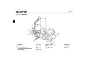 12
12 13
13 14
14 15
15 16
16 17
17 18
18 19
19 20
20 21
21 22
22 23
23 24
24 25
25 26
26 27
27 28
28 29
29 30
30 31
31 32
32 33
33 34
34 35
35 36
36 37
37 38
38 39
39 40
40 41
41 42
42 43
43 44
44 45
45 46
46 47
47 48
48 49
49 50
50 51
51 52
52 53
53 54
54 55
55 56
56 57
57 58
58 59
59 60
60 61
61 62
62 63
63 64
64 65
65 66
66 67
67 68
68 69
69 70
70 71
71 72
72 73
73 74
74 75
75 76
76 77
77 78
78 79
79 80
80 81
81 82
82 83
83 84
84 85
85 86
86 87
87 88
88 89
89 90
90 91
91 92
92 93
93 94
94 95
95 96
96 97
97 98
98 99
99 100
100 101
101 102
102 103
103 104
104 105
105
Passenger seat
To remove the passenger seatRemove the nut, and then pull the pas-
senger seat up.To install the passenger seat
Insert the")
Passenger seat
To remove the passenger seatRemove the bolt, and then pull the pas-
senger seat up.To install the passenger seat
Insert")

