Page 17 of 94

EAU00152
Clutch leverThe clutch lever is located at the left
handlebar grip. To disengage the
clutch, pull the lever toward the han-
dlebar grip. To engage the clutch,
release the lever. The lever should
be pulled rapidly and released slowly
for smooth clutch operation.
The clutch lever is equipped with a
clutch switch, which is part of the igni-
tion circuit cut-off system. (See page
3-16 for an explanation of the ignition
circuit cut-off system.)
3-6
INSTRUMENT AND CONTROL FUNCTIONS
1
23
4
5
6
7
8
9
1
1.Clutch lever
6
5
4
3
2
1 N
1
EAU00157
Shift pedalThe shift pedal is located on the left
side of the engine and is used in
combination with the clutch lever
when shifting the gears of the
6-speed constant-mesh transmission
equipped on this motorcycle.1.Shift pedal
N.Neutral
21
EAU00138
Engine stop switch
Set this switch to Ò$Ó to stop the
engine in case of an emergency,
such as when the motorcycle over-
turns or when the throttle cable is
stuck.
EAU00143
Start switch Ò,Ó
Push this switch to crank the engine
with the starter.
EC000005
cCSee page 5-1 for starting instruc-
tions prior to starting the engine.1.Engine stop switch
2.Start switch Ò,Ó
5AE-9-E4 (ENG) 8/30/00 5:04 PM Page 16
Page 18 of 94
3-7
1
EAU00158
Brake leverThe brake lever is located at the right
handlebar grip. To apply the front
brake, pull the lever toward the han-
dlebar grip.1.Brake lever
INSTRUMENT AND CONTROL FUNCTIONS
1
23
4
5
6
7
8
9
1
1.Brake pedal
EAU00162
Brake pedalThe brake pedal is on the right side
of the motorcycle. To apply the rear
brake, press down on the brake
pedal.
1
a
b
EAU02935
Fuel tank capTo open the fuel tank cap
Open the fuel tank cap lock cover,
insert the key into the lock, and then
turn it 1/4 turn clockwise. The lock will
be released and the fuel tank cap can
be opened.
To close the fuel tank cap
1.Push the fuel tank cap into posi-
tion with the key inserted in the
lock.
2.Turn the key counterclockwise to
the original position, remove it,
and then close the lock cover.1.Fuel tank cap lock cover
a.Open.
b.Unlock.
5AE-9-E4 (ENG) 8/30/00 5:04 PM Page 17
Page 19 of 94

3-8
INSTRUMENT AND CONTROL FUNCTIONS
1
23
4
5
6
7
8
9
NOTE:
The fuel tank cap cannot be closed
unless the key is in the lock. In addi-
tion, the key cannot be removed if the
cap is not properly closed and
locked.
EWA00025
wMake sure that the fuel tank cap is
properly closed before riding.
2
1
1.Filler tube
2.Fuel level
EAU03753
Fuel(except for Switzerland and
Austria)
Make sure that there is sufficient fuel
in the tank. Fill the fuel tank to the
bottom of the filler tube as shown.
EW000130
w8Do not overfill the fuel tank,
otherwise it may overflow
when the fuel warms up and
expands.
8Avoid spilling fuel on the hot
engine.
1
3 5 42
1.Pump nozzle
2.Fuel tank filler hole
3.Filler tube
4.Fuel level
5.Leaf valve
EAU03754
Fuel(for Switzerland and Austria)
Make sure that there is sufficient fuel
in the tank. When refueling, be sure
to insert the pump nozzle into the fuel
tank filler hole and to fill the tank to
the bottom of the filler tube as shown.
5AE-9-E4 (ENG) 8/30/00 5:04 PM Page 18
Page 20 of 94
3-9
INSTRUMENT AND CONTROL FUNCTIONS
1
23
4
5
6
7
8
9
EW000130
w8Do not overfill the fuel tank,
otherwise it may overflow
when the fuel warms up and
expands.
8Avoid spilling fuel on the hot
engine.
EAU00185
cCImmediately wipe off spilled fuel
with a clean, dry, soft cloth, since
fuel may deteriorate painted sur-
faces or plastic parts.
EAU00191
NOTE:
If knocking (or pinging) occurs, use
gasoline of a different brand or with a
higher octane grade.
EAU01084
Catalytic converter(for Switzerland and Austria)
This motorcycle is equipped with a
catalytic converter in the exhaust
chamber.
EW000128
wThe exhaust system is hot after
operation. Make sure that the
exhaust system has cooled down
before doing any maintenance
work.
Recommended fuel:
Regular unleaded gasoline
with a research octane
number of 91 or higher
Fuel tank capacity:
Total amount:
11.0 L
Reserve amount:
2.2 L
5AE-9-E4 (ENG) 8/30/00 5:04 PM Page 19
Page 21 of 94
3-10
INSTRUMENT AND CONTROL FUNCTIONS
1
23
4
5
6
7
8
9
EC000114
cCThe following precautions must be
observed to prevent a fire hazard
or other damages.
8Use only unleaded gasoline.
The use of leaded gasoline will
cause unrepairable damage to
the catalytic converter.
8Never park the motorcycle
near possible fire hazards
such as grass or other materi-
als that easily burn.
8Do not allow the engine to idle
too long.
EAU03750
2-stroke engine oilMake sure that there is sufficient oil in
the 2-stroke engine oil tank. Add the
recommended 2-stroke engine oil if
necessary.NOTE:
Make sure that the 2-stroke engine
oil tank cap is properly installed.
1
1.2-stroke engine oil tank cap
Recommended oil:
Yamalube 2 or equivalent
2-stroke engine oil (JASO
grade ÒFCÓ, or ISO grades
ÒEG-CÓ or ÒEG-DÓ)
Oil quantity:
1.2 L
5AE-9-E4 (ENG) 8/30/00 5:04 PM Page 20
Page 22 of 94
3-11
INSTRUMENT AND CONTROL FUNCTIONS
1
23
4
5
6
7
8
9
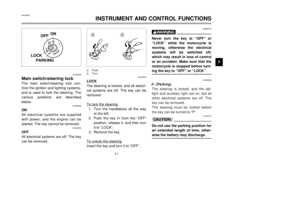
ON
1
1.Arrow mark positioned over ÒONÓ
EAU03050
Fuel cockThe fuel cock supplies fuel from the
tank to the carburetor while filtering it
also.
The fuel cock has three positions:
OFF
With the lever in this position, fuel will
not flow. Always return the lever to
this position when the engine is not
running.ON
With the lever in this position, fuel
flows to the carburetor. Normal riding
is done with the lever in this position.
1
OFF
1.Arrow mark positioned over ÒOFFÓOFF: closed position
ON: normal position
RES
This indicates reserve. If you run out
of fuel while riding, move the lever to
this position. Fill the tank at the first
opportunity. Be sure to set the lever
back to ÒONÓ after refueling!
1
RES
1.Arrow mark positioned over ÒRESÓRES: reserve position
5AE-9-E4 (ENG) 8/30/00 5:04 PM Page 21
Page 23 of 94
a
EAU01619
SeatTo remove the seat
1.Insert the key into the seat lock,
and then turn it clockwise.
2.Pull the seat off.a.Unlock.
3-12
INSTRUMENT AND CONTROL FUNCTIONS
1
23
4
5
6
7
8
9To install the seat
1.Insert the projection on the front
of the seat into the seat holder
as shown.
2.Push the rear of the seat down to
lock it in place.
3.Turn the key counterclockwise,
and then remove it.
NOTE:
Make sure that the seat is properly
secured before riding.
1
2
1.Projection
2.Seat holder
1
a
b
EAU02976
Starter (choke) lever Ò
1Ó
Starting a cold engine requires a rich-
er air-fuel mixture, which is supplied
by the starter (choke).
Move the lever in direction ato turn
on the starter (choke).
Move the lever in direction bto turn
off the starter (choke).1.Starter (choke) lever Ò1Ó
5AE-9-E4 (ENG) 8/30/00 5:04 PM Page 22
Page 24 of 94

3-13
INSTRUMENT AND CONTROL FUNCTIONS
1
23
4
5
6
7
8
9
EAU00260
Helmet holderTo open the helmet holder, insert the
key into the lock, and then turn the
key as shown.
To lock the helmet holder, place it in
the original position, and then remove
the key.
EW000030
wNever ride with a helmet attached
to the helmet holder, since the hel-
met may hit objects, causing loss
of control and possibly an acci-
dent.
EAU00295
Adjusting the shock
absorber assemblyThis shock absorber assembly is
equipped with a spring preload
adjusting ring.
EC000015
cCNever attempt to turn an adjusting
mechanism beyond the maximum
or minimum settings.
a
a.Open.
a
b1
1.Spring preload adjusting ringAdjust the spring preload as follows.
To increase the spring preload and
thereby harden the suspension, turn
the adjusting ring in direction a. To
decrease the spring preload and
thereby soften the suspension, turn
the adjusting ring in direction b.NOTE:
Align the appropriate notch in the
adjusting ring with the position indica-
tor on the shock absorber.
5AE-9-E4 (ENG) 8/30/00 5:04 PM Page 23