2001 YAMAHA TDM 850 clutch
[x] Cancel search: clutchPage 14 of 110

DESCRIPTION
2-3
2
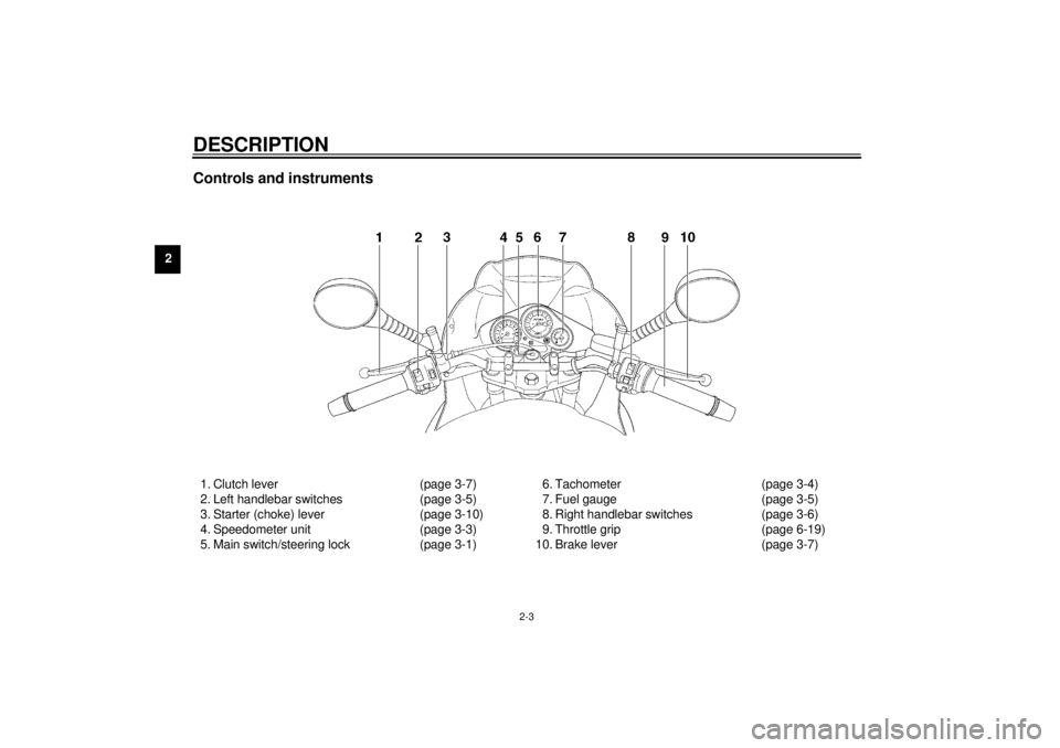
Controls and instruments1. Clutch lever (page 3-7)
2. Left handlebar switches (page 3-5)
3. Starter (choke) lever (page 3-10)
4. Speedometer unit (page 3-3)
5. Main switch/steering lock (page 3-1)6. Tachometer (page 3-4)
7. Fuel gauge (page 3-5)
8. Right handlebar switches (page 3-6)
9. Throttle grip (page 6-19)
10. Brake lever (page 3-7)
E_4tx.book Page 3 Wednesday, October 4, 2000 4:28 PM
Page 15 of 110

3
INSTRUMENT AND CONTROL FUNCTIONS
Main switch/steering lock ..................................... 3-1
Indicator and warning lights ................................ 3-2
Speedometer unit ................................................ 3-3
Tachometer .......................................................... 3-4
Self-diagnosis device .......................................... 3-4
Anti-theft alarm (optional) .................................... 3-5
Fuel gauge ........................................................... 3-5
Handlebar switches ............................................. 3-5
Clutch lever .......................................................... 3-7
Shift pedal ............................................................ 3-7
Brake lever .......................................................... 3-7
Brake pedal .......................................................... 3-8
Fuel tank cap ....................................................... 3-9Fuel ..................................................................... 3-9
Fuel tank breather hose (for Germany only) ..... 3-10
Starter (choke) lever .......................................... 3-10
Seat ................................................................... 3-11
Helmet holder .................................................... 3-11
Storage compartment ....................................... 3-12
Adjusting the front fork ...................................... 3-13
Adjusting the shock absorber assembly ............ 3-15
Luggage strap holders ...................................... 3-17
Sidestand .......................................................... 3-17
Ignition circuit cut-off system ............................. 3-18
E_4tx.book Page 1 Wednesday, October 4, 2000 4:28 PM
Page 17 of 110

INSTRUMENT AND CONTROL FUNCTIONS
3-2
3
EAU01590
(Parking)
The steering is locked, and the taillight
and auxiliary light are on, but all other
electrical systems are off. The key can
be removed.
The steering must be locked before the
key can be turned to “ ”.
ECA00043
CAUTION:_ Do not use the parking position for
an extended length of time, other-
wise the battery may discharge. _
EAU03034
Indicator and warning lights
EAU03299
Turn signal indicator lights
“”/“”
The corresponding indicator light flash-
es when the turn signal switch is
pushed to the left or right.
EAU00061
Neutral indicator light “ ”
This indicator light comes on when the
transmission is in the neutral position.
EAU00063
High beam indicator light “ ”
This indicator light comes on when the
high beam of the headlight is switched
on.
EAU01707
Coolant temperature warning light
“”
This warning light comes on when the
engine overheats. When this occurs,
stop the engine immediately and allow
the engine to cool.
The electrical circuit of the warning light
can be checked according to the fol-
lowing procedure.
1. Set the engine stop switch to “ ”
and turn the key to “ON”.
2. Shift the transmission into the neu-
tral position or pull the clutch lever.
3. Push the start switch. If the warn-
ing light does not come on while
pushing the start switch, have a
Yamaha dealer check the electri-
cal circuit.
EC000002
CAUTION:@ Do not operate the engine if it is
overheated. @
1. Left turn signal indicator light “ ”
2. Neutral indicator light “ ”
3. High beam indicator light “ ”
4. Coolant temperature warning light “ ”
5. Right turn signal indicator light “ ”
6. Fuel level warning light “ ”
E_4tx.book Page 2 Wednesday, October 4, 2000 4:28 PM
Page 18 of 110

INSTRUMENT AND CONTROL FUNCTIONS
3-3
3
EAU03680
Fuel level warning light “ ”
This warning light comes on when the
fuel level drops below approximately
3.1 L. When this occurs, refuel as soon
as possible.
The electrical circuit of the warning light
can be checked according to the fol-
lowing procedure.
1. Set the engine stop switch to “ ”
and turn the key to “ON”.
2. Shift the transmission into the neu-
tral position or pull the clutch lever.
3. Push the start switch. If the warn-
ing light does not come on, have a
Yamaha dealer check the electri-
cal circuit.
EAU03492
Speedometer unit The speedometer unit is equipped with
the following:l
a speedometer (which shows the
riding speed)
l
an odometer (which shows the to-
tal distance traveled)
l
two tripmeters (which show the
distance traveled since they were
last set to zero)
l
a clockOdometer and tripmeter modes
Pushing the “SELECT” button switches
the display between the odometer
mode “ODO” and the tripmeter modes
“TRIP 1”, “TRIP 2” and “CLOCK” in the
following order:
ODO
®TRIP 1
®TRIP 2
®CLOCK
®
ODO
To reset a tripmeter, select it by push-
ing the “SELECT” button, and then
push the “RESET” button for at least
one second. The tripmeters can be
used to estimate the distance that can
be traveled with a full tank of fuel. This
information will enable you to plan fu-
ture fuel stops.
Clock mode
To change the display to the clock
mode, push both the “SELECT” and
“RESET” buttons.
To change the display back to the
odometer mode, push the “SELECT”
button.
1. Speedometer
2. Odometer/tripmeter/clock
3. “SELECT” button
4. “RESET” button
E_4tx.book Page 3 Wednesday, October 4, 2000 4:28 PM
Page 22 of 110

INSTRUMENT AND CONTROL FUNCTIONS
3-7
3
EAU00152
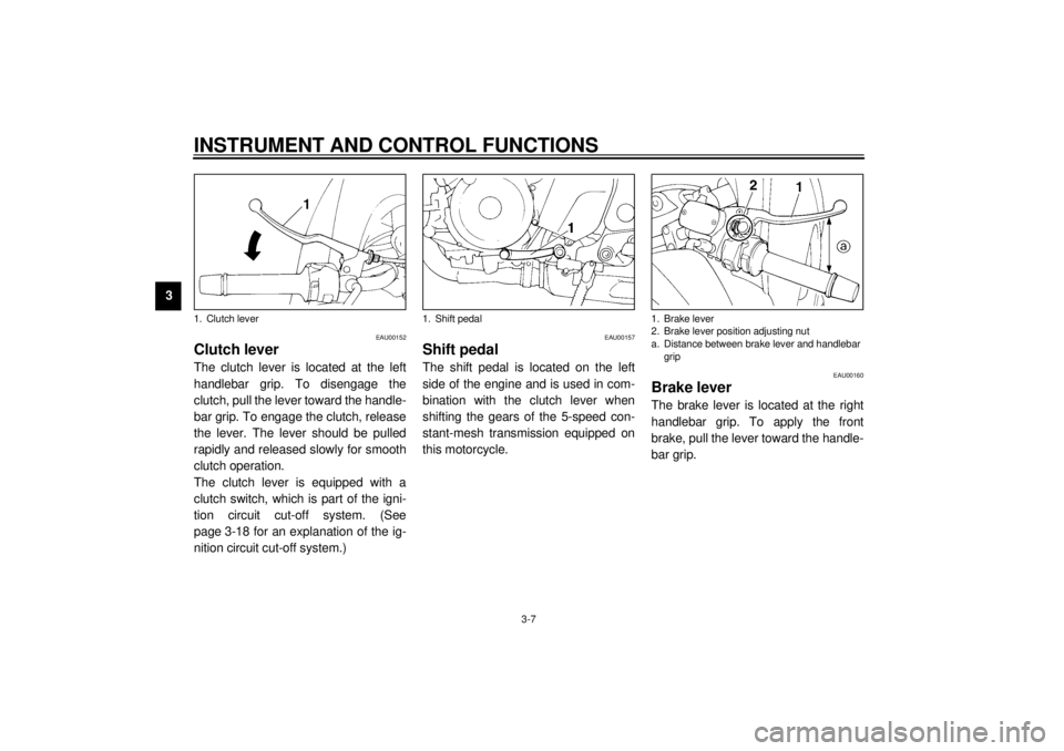
Clutch lever The clutch lever is located at the left
handlebar grip. To disengage the
clutch, pull the lever toward the handle-
bar grip. To engage the clutch, release
the lever. The lever should be pulled
rapidly and released slowly for smooth
clutch operation.
The clutch lever is equipped with a
clutch switch, which is part of the igni-
tion circuit cut-off system. (See
page 3-18 for an explanation of the ig-
nition circuit cut-off system.)
EAU00157
Shift pedal The shift pedal is located on the left
side of the engine and is used in com-
bination with the clutch lever when
shifting the gears of the 5-speed con-
stant-mesh transmission equipped on
this motorcycle.
EAU00160
Brake lever The brake lever is located at the right
handlebar grip. To apply the front
brake, pull the lever toward the handle-
bar grip.
1. Clutch lever
1. Shift pedal
1. Brake lever
2. Brake lever position adjusting nut
a. Distance between brake lever and handlebar
grip
E_4tx.book Page 7 Wednesday, October 4, 2000 4:28 PM
Page 33 of 110

INSTRUMENT AND CONTROL FUNCTIONS
3-18
3
EW000044
WARNING
@ The motorcycle must not be ridden
with the sidestand down, or if the
sidestand cannot be properly
moved up (or does not stay up), oth-
erwise the sidestand could contact
the ground and distract the opera-
tor, resulting in a possible loss of
control. Yamaha’s ignition circuit
cut-off system has been designed to
assist the operator in fulfilling the
responsibility of raising the side-
stand before starting off. Therefore,
check this system regularly as de-
scribed below and have a Yamaha
dealer repair it if it does not function
properly. @
EAU03720
Ignition circuit cut-off system The ignition circuit cut-off system (com-
prising the sidestand switch, clutch
switch and neutral switch) has the fol-
lowing functions.l
It prevents starting when the trans-
mission is in gear and the side-
stand is up, but the clutch lever is
not pulled.
l
It prevents starting when the trans-
mission is in gear and the clutch
lever is pulled, but the sidestand is
still down.
l
It cuts the running engine when
the transmission is in gear and the
sidestand is moved down.
Periodically check the operation of the
ignition circuit cut-off system according
to the following procedure.
EW000045
WARNING
_ If a malfunction is noted, have a
Yamaha dealer check the system
before riding. _
E_4tx.book Page 18 Wednesday, October 4, 2000 4:28 PM
Page 34 of 110

INSTRUMENT AND CONTROL FUNCTIONS
3-19
3
CD-01E
With the engine turned off:
1. Move the sidestand down.
2. Make sure that the engine stop switch is set to “ ”.
3. Turn the key to “ON”.
4. Shift the transmission into the neutral position.
5. Push the start switch.
Does the engine start?
The neutral switch may be defective.
The motorcycle should not be ridden until
checked by a Yamaha dealer.
With the engine still running:
6. Move the sidestand up.
7. Keep the clutch lever pulled.
8. Shift the transmission into gear.
9. Move the sidestand down.
Does the engine stall?After the engine has stalled:
10. Move the sidestand up.
11. Keep the clutch lever pulled.
12. Push the start switch.
Does the engine start?
The sidestand switch may be defective.
The motorcycle should not be ridden until
checked by a Yamaha dealer.The clutch switch may be defective.
The motorcycle should not be ridden until
checked by a Yamaha dealer.
NO
NOTE:This check is most reliable if performed with
a warmed-up engine.
YESYES NO
The system is OK.
The motorcycle can be ridden.
YES NO
E_4tx.book Page 19 Wednesday, October 4, 2000 4:28 PM
Page 36 of 110

4-1
4
EAU01114
4-PRE-OPERATION CHECKSThe condition of a vehicle is the owner’s responsibility. Vital components can start to deteriorate quickly and unexpectedly,
even if the vehicle remains unused (for example, as a result of exposure to the elements). Any damage, fluid leakage or loss
of tire air pressure could have serious consequences. Therefore, it is very important, in addition to a thorough visual inspec-
tion, to check the following points before each ride.
EAU03439
Pre-operation check list
CO-01E
ITEM CHECKS PAGE
Fuel• Check fuel level in fuel tank.
• Refuel if necessary.
• Check fuel line for leakage.3-9–3-10
Engine oil• Check oil level in engine.
• If necessary, add recommended oil to specified level.
• Check vehicle for oil leakage.6-9
Coolant• Check coolant level in reservoir.
• If necessary, add recommended coolant to specified level.
• Check cooling system for leakage.6-11–6-13
Front brake• Check operation.
• If soft or spongy, have Yamaha dealer bleed hydraulic system.
• Check fluid level in reservoir.
• If necessary, add recommended brake fluid to specified level.
• Check hydraulic system for leakage.6-25–6-26
Rear brake• Check operation.
• If soft or spongy, have Yamaha dealer bleed hydraulic system.
• Check fluid level in reservoir.
• If necessary, add recommended brake fluid to specified level.
• Check hydraulic system for leakage.6-23–6-26
Clutch• Check operation.
• Lubricate cable if necessary.
• Check lever free play.
• Adjust if necessary.6-23
Throttle grip• Make sure that operation is smooth.
• Lubricate throttle grip, housing and cables if necessary.
• Check free play.
• If necessary, have Yamaha dealer make adjustment.6-19
E_4tx.book Page 1 Wednesday, October 4, 2000 4:28 PM