Page 89 of 107

4-20
E
EJU00578
Replacing the fuse
The fuse is in the electrical box 1.
To replace the fuse:
1. Remove the cap 2, pull out the red lead,
and bring the fuse holder 3 out of the
electrical box.
2. Open the fuse holder and replace the
fuse4 with one of the correct amper-
age.
WARNING@Do not use fuses of higher amperage
than those recommended. Substitution
of a fuse of improper rating can cause
extensive electrical system damage and
possible fire.
@
Fuse amperage: 10 A
EJU00582
Adjusting the steering friction
The amount of friction in the steering can
be adjusted to suit operator preference.
To adjust the friction:
1. Loosen the four screws, and then
remove the handlebar cover.
2. Turn the handlebars as far as possible to
starboard (right).
3. Loosen the locknut 2.
4. Tighten or loosen the adjusting nut 1
until the desired amount of friction is
reached.
5. Hold the adjusting nut with one wrench
while tightening the locknut with another
wrench.
Tightening torque:
29 Nm (2.9 m·kg, 21 ft·lb)
E_GM6-4.fm Page 20 Tuesday, July 11, 2000 11:28 AM
Page 90 of 107
4-21
E
EJU00953
Adjusting the jet thrust nozzle
angle
The angle of the jet thrust nozzle can be
adjusted to suit operator preference.
1. Loosen the two screws, and then remove
the steering pole cover 1.
2. Select the desired nozzle angle a.
Changing the position of the handlebar
stopper and/or steering cable pivot bolt
changes the nozzle angle as shown in
the following chart.
E_GM6-4.fm Page 21 Tuesday, July 11, 2000 11:28 AM
Page 91 of 107
4-22
E
To change the position for the steering
cable pivot bolt:
1. Pull back the outer sleeve, and then dis-
connect the steering cable.
2. Remove the steering cable joint from the
steering cable pivot bolt.
3. Loosen the pivot bolt and install it with
the lock washer in the desired position
(P1 or P2). Make sure to tighten it to the
specified torque.
4. Install the steering cable joint on the
steering cable pivot bolt.
To change the handlebar stopper posi-
tion:
1. Loosen the handle stopper nut 2 on the
operator’s side of the steering pole.
2. Lift and turn the handlebar stopper to the
desired position (S1 or S2), and then
tighten the handlebar stopper nut. Make
sure to tighten it to the specified torque.
3. Install the steering pole cover securely. Tightening torque:
5.4 Nm (0.5 m·kg, 3.9 ft·lb)
Tightening torque:
31 Nm (3.1 m·kg, 22.4 ft·lb)
E_GM6-4.fm Page 22 Tuesday, July 11, 2000 11:28 AM
Page 92 of 107
 2,240 (8")
4-23
E
EJU00590
Specifications
*1: Pump Octane Number
*1: Research Octane NumberMODEL
ITEMUnit SJ700
WATERCRAFT CAPACITY
Maximum people on board Number of people 1
DIMENSIONS
Length mm (in) 2,240 (88.2)
Width mm (in) 680 (26.8)
Height mm (in) 660 (26.0)
Dry weight kg (lb) 132 (291)
PERFORMANCE
Maximum power output kW (PS) @ r/min 53.6 (73) @ 6,300
Maximum fuel consumption L/h (US gal/h, Imp gal/h) 29 (7.7, 6.4)
Cruising range at full throttle hr. 0.6
Trolling speed r/min 1,250–1,350
ENGINE
Engine type 2-stroke
Number of cylinders 2
Engine displacement
cm
3 (cu in)701 (42.78)
Bore & stroke mm (in) 81 ×
68 (3.19 ×
2.68)
Compression ratio 7.2
Lubrication system Pre-mixed fuel
Cooling system Water cooled
Starting system Electric starter
Ignition system CDI
Spark plug BR-7HS (NGK)
Spark plug gap mm (in) 0.6–0.7 (0.024–0.028)
Battery capacity V-AH 12-19
Charging system Flywheel magneto
DRIVE UNIT
Propulsion system Jet pump
Jet pump type Mixed flow, single stage
Impeller rotation Counterclockwise (viewed from rear)
Transmission Direct drive from engine
Jet thrust nozzle angle Degree 37, 41, 45, 49
FUEL AND OIL
Recommended fuel Regular unleaded gasoline
Minimum octane rating PON (*1)
RON (*1)86
90
Recommended engine oil YAMALUBE 2-W, or an equivalent NMMA-
certified TC-W3 marine oil
Fuel mixing ratio (fuel to oil) 50:1
Fuel tank capacity
Total L (US gal, Imp gal) 18 (4.8, 4.0)
Reserve L (US gal, Imp gal) 5.5 (1.45, 1.21)
E_GM6-4.fm Page 23 Tuesday, July 11, 2000 11:28 AM
Page 93 of 107
E
5
EJU00594
TROUBLESHOOTING
AND EMERGENCY
PROCEDURES
Troubleshooting....................................... 5-1
Troubleshooting chart ............................ 5-1
Emergency procedures........................... 5-3
Cleaning the jet intake and impeller ....... 5-3
Jumping the battery ................................ 5-4
Towing the watercraft ............................. 5-6
Submerged watercraft ............................ 5-7
E_GM6-5TOC.fm Page 1 Tuesday, July 11, 2000 11:29 AM
Page 94 of 107

5-1
E
EJU00595
Troubleshooting
If you have any trouble with your watercraft, use this section to check for the possible
cause.
If you cannot find the cause, or if the procedure for replacement or repair is not described
in this Owner’s/Operator’s manual, have a Yamaha dealer perform the necessary service.
EJU00596
Troubleshooting chart
TROUBLE POSSIBLE CAUSE REMEDY PAGE
Engine does not
startStarter motor does not turn over
Engine shut-
off switch Clip not in place Install clip
2-5
Fuse Burned out Replace fuse and check
wiring4-20
Battery Run down Recharge 4-18
Poor terminal connec-
tionsTighten as required
4-18
Starter motor Faulty Have serviced by
Yamaha dealer—
Starter motor turns over
Fuel cock Turned to “OFF” Turn fuel cock knob to
“ON”2-4
Fuel Empty Refill as soon as possi-
ble3-4
Stale or contaminated Have serviced by
Yamaha dealer4-10
Fuel tank Water or dirt present Have serviced by
Yamaha dealer4-11
Spark plug Fouled or defective Clean or replace 4-13
Spark plug cap Not connected or loose Connect properly 4-13
Crankcase Filled with water Crank engine with plug
out until clean5-7
Fuel filter Clogged or water
pooledHave serviced by
Yamaha dealer4-11
Choke Knob moves back on
its ownTighten choke knob
adjusting nut4-16
E_GM6-5.fm Page 1 Tuesday, July 11, 2000 11:29 AM
Page 95 of 107

5-2
E
Engine runs irregu-
larly or stallsFuel Empty Refill as soon as possi-
ble3-4
Stale or contaminated Have serviced by
Yamaha dealer4-10
Too much oil in fuel
mixing ratioCorrect fuel-to-oil ratio
to 50:13-3
Choke Knob is left pulled Push fully in 2-6
Fuel filter Clogged or water
pooledHave serviced by
Yamaha dealer4-11
Fuel tank Water or dirt present Have serviced by
Yamaha dealer4-11
Spark plug Fouled or defective Replace 4-13
Incorrect heat range Replace 4-13
Gap incorrect Adjust 4-13
Spark plug cap Loose Connect properly 4-13
Cracked, torn or dam-
agedReplace
4-13
Electrical wir-
ingLoose electrical con-
nectionsTighten or connect
properly—
Carburetor Incorrect idle adjust-
mentAdjust idle
4-19
Clogged Have serviced by
Yamaha dealer4-19
Wate rcr af t slow or
loses powerCavitation Jet intake clogged Clean 5-3
Impeller damaged or
wornHave serviced by
Yamaha dealer5-3
Engine over-
heatedJet intake clogged Clean
5-3
Fuel filter Clogged Have serviced by
Yamaha dealer4-11
Spark plug Fouled or defective Replace 4-13
Incorrect heat range Replace 4-13
Gap incorrect Adjust 4-13
Spark plug
capsLoose Connect properly
4-13
Fuel Stale or contaminated Have serviced by
Yamaha dealer4-10 TROUBLE POSSIBLE CAUSE REMEDY PAGE
E_GM6-5.fm Page 2 Tuesday, July 11, 2000 11:29 AM
Page 96 of 107

5-3
E
EJU00597
Emergency procedures
Cleaning the jet intake and
impeller
If weeds or debris get caught in the intake
or impeller, cavitation can occur, causing jet
thrust to decrease even though engine
speed rises. If this condition is allowed to
continue, the engine will overheat and may
seize. If there is any sign that the jet intake
or impeller is clogged with weeds or debris,
beach the watercraft and check the intake
and impeller. Always stop the engine before
beaching the watercraft.
WARNING@Before attempting to remove weeds or
debris from the jet intake or impeller
areas, shut the engine off and remove
the clip from the engine shut-off switch.
Severe injury or death could result from
coming in contact with the rotating parts
of the jet pump.
@
1. Turn the watercraft on its side as shown.
CAUTION:@●Place a suitable clean cloth or carpet-
ing underneath the watercraft to pro-
tect it from abrasions and scratches.
●Always turn the watercraft over onto
its port (left) side.
●When turning the watercraft on its
side, support the bow and secure the
steering pole, otherwise the steering
pole and handlebars could be bent or
damaged.
@
2. Remove any weeds or debris from
around the drive shaft, impeller, and jet
thrust nozzle.
If debris is difficult to remove, consult
your Yamaha dealer.
E_GM6-5.fm Page 3 Tuesday, July 11, 2000 11:29 AM
 1
1 2
2 3
3 4
4 5
5 6
6 7
7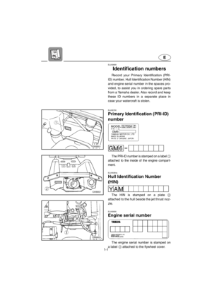 8
8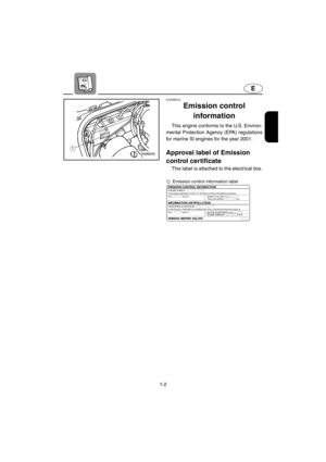 9
9 10
10 11
11 12
12 13
13 14
14 15
15 16
16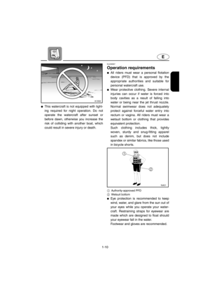 17
17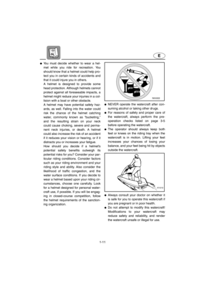 18
18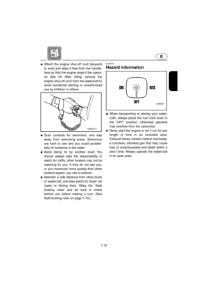 19
19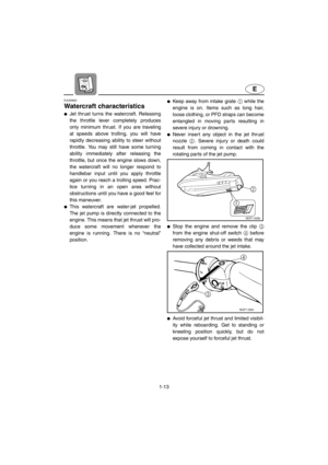 20
20 21
21 22
22 23
23 24
24 25
25 26
26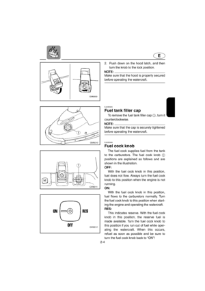 27
27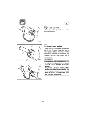 28
28 29
29 30
30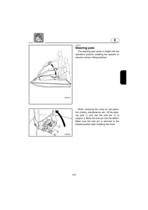 31
31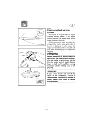 32
32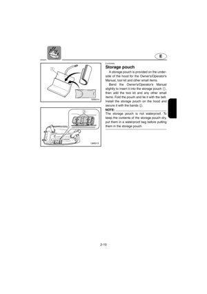 33
33 34
34 35
35 36
36 37
37 38
38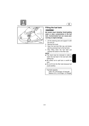 39
39 40
40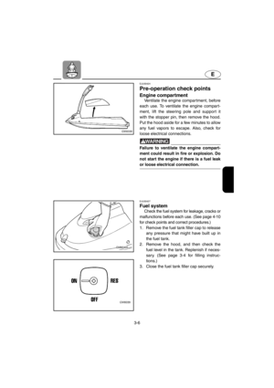 41
41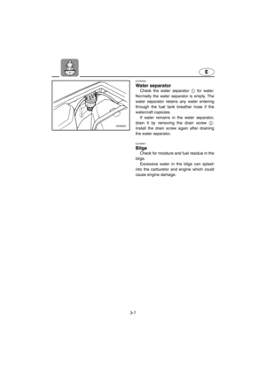 42
42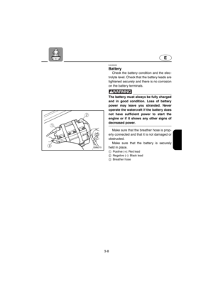 43
43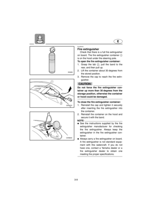 44
44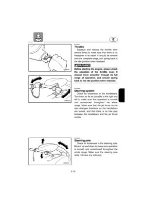 45
45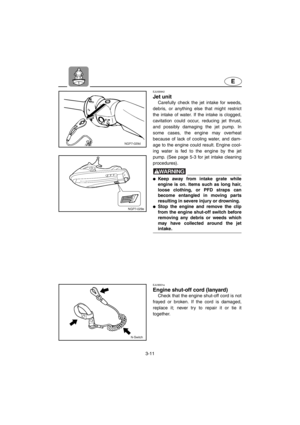 46
46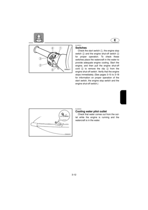 47
47 48
48 49
49 50
50 51
51 52
52 53
53 54
54 55
55 56
56 57
57 58
58 59
59 60
60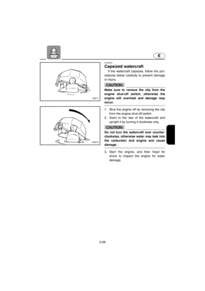 61
61 62
62 63
63 64
64 65
65 66
66 67
67 68
68 69
69 70
70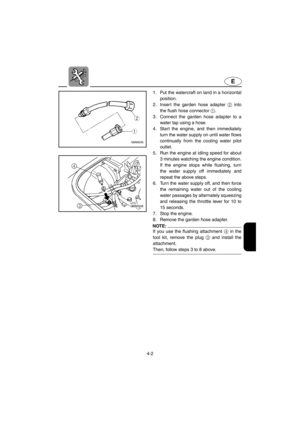 71
71 72
72 73
73 74
74 75
75 76
76 77
77 78
78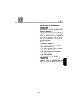 79
79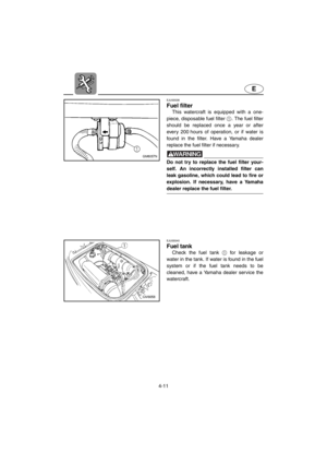 80
80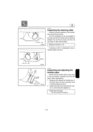 81
81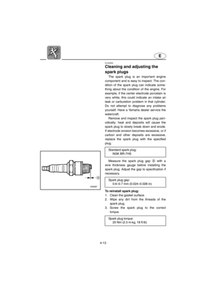 82
82 83
83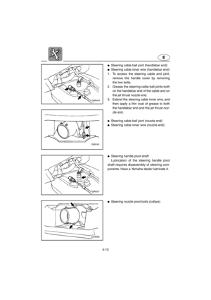 84
84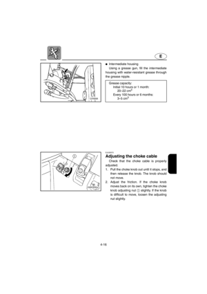 85
85 86
86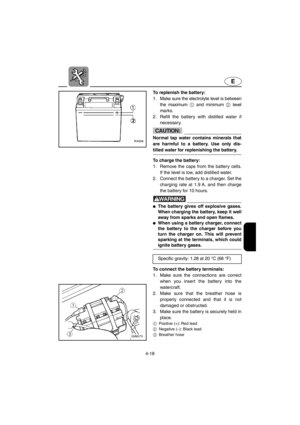 87
87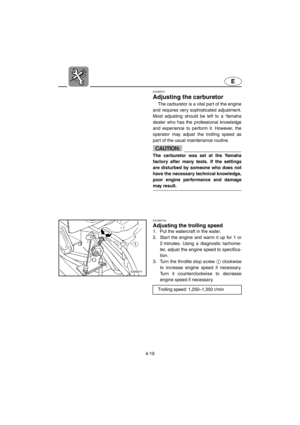 88
88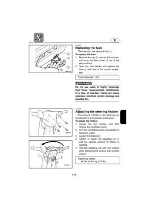 89
89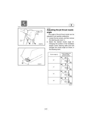 90
90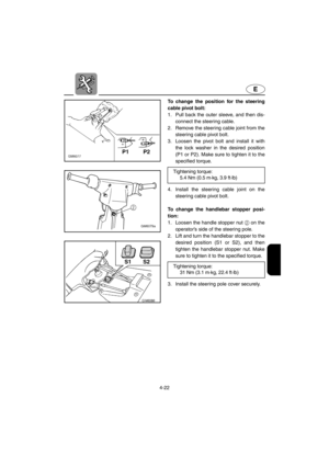 91
91 92
92 93
93 94
94 95
95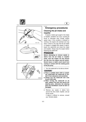 96
96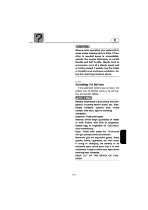 97
97 98
98 99
99 100
100 101
101 102
102 103
103 104
104 105
105 106
106

