Page 598 of 4323
DI±396
± DIAGNOSTICSENGINE
590 Author�: Date�:
2005 SEQUOIA (RM1146U)
6 Replace air fuel ratio sensor.
NEXT
7 Perform confirmation driving pattern.
NEXT
8 Check whether DTC output recurs (DTC P2195, P2196, P2197 or P2198)
CHECK:
(a) On the hand±held tester, select the following menu items: DIAGNOSIS / ENHANCED OBD II / DTC
INFO / PENDING CODES.
(b) Read DTCs.
RESULT:
Display (DTC Output)Proceed To
P2195, P2196, P2197 or P2198A
No outputB
B Go to step 5.
A
9 Confirm whether vehicle has run out of fuel in past.
NO Check for intermittent problems
(See page DI±11).
YES
DTC caused by running out of fuel.
Page 599 of 4323
B17396
HT +B
AF± AF+ Sensor 1A/F Sensor Component Side:
Front View
A19288
A/F Relay
± DIAGNOSTICSENGINE
DI±397
591 Author�: Date�:
2005 SEQUOIA (RM1146U)
10 Check resistance of air±fuel ratio (A/F) sensor heater.
PREPARATION:
Disconnect the air±fuel ratio (A/F) sensor connector.
CHECK:
Measure resistance between the terminals of the A/F sensor
connector.
OK:
Tester ConnectionSpecified Condition
HT (1) ± +B (2)Between 1.8 W and 3.4 W at 20�C (68�F)
HT (1) ± AF± (4)10 kW or higher
NG Replace air±fuel ratio (A/F) sensor.
OK
11 Check A/F relay.
PREPARATION:
Remove the A/F relay from the engine room J/B.
CHECK:
Inspect the A/F relay.
OK:
Standard:
Terminal No.ConditionSpecified Condition
3 ± 5Always10 KW or higher
3 ± 5Apply B+ between
terminals 1 and 2Below 1 W
NG Replace EFI relay.
OK
Page 600 of 4323
:
A")
A23659
Wire Harness Side:
HT
A38
Sensor 1A/F Sensor Connector
AF+
Front ViewAF±
+B A39
B17415A55007
E7ECM Connector
HA1A
A1A+
A1A±
A2A+
A2A±HA2A
A23512
Reference (Bank 1 Sensor 1 System Drawing):
A/F Sensor A/F Relay
Heater
Sensor
A1A+ HA1A
Duty
Control ECM
From
Battery
A/F Heater
Fuse
A1A±
To EFI Relay DI±398
± DIAGNOSTICSENGINE
592 Author�: Date�:
2005 SEQUOIA (RM1146U)
12 Check for open and short in harness and connector between ECM and A/F sen-
sor.
PREPARATION:
(a) Disconnect the A38 or A39 A/F sensor connector.
(b) Turn the ignition switch to ON.
CHECK:
(a) Measure the voltage between the +B terminal of the A/F
sensor connector and body ground.
Standard:
Tester ConnectionsSpecified Conditions
+B (2) ± Body groundBetween 9 V and 14 V
PREPARATION:
(a) Turn the ignition switch to OFF.
(b) Disconnect the E7 ECM connector.
CHECK:
(a) Check the resistance.
Standard (Check for open):
Tester ConnectionsSpecified Conditions
HT (A38±1) ± HA1A (E7±2)
HT (A39±1) ± HA2A (E7±1)Below 1 W
AF+ (A38±3) ± A1A+ (E7±22)
AF+ (A39±3) ± A2A+ (E7±23)Below 1 W
AF± (A38±4) ± A1A± (E7±30)
AF± (A39±4) ± A2A± (E7±31)Below 1 W
Standard (Check for short):
Tester ConnectionsSpecified Conditions
HT (A38±1) or HA1A (E7±2) ± Body ground
HT (A39±1) or HA2A (E7±1) ± Body ground10 kW or higher
AF+ (A38±3) or A1A+ (E7±22) ± Body ground
AF+ (A39±3) or A2A+ (E7±23) ± Body ground10 kW or higher
AF± (A38±4) or A1A± (E7±30) ± Body ground
AF± (A39±4) or A2A± (E7±31) ± Body ground10 kW or higher
Page 601 of 4323
± DIAGNOSTICSENGINE
DI±399
593 Author�: Date�:
2005 SEQUOIA (RM1146U)
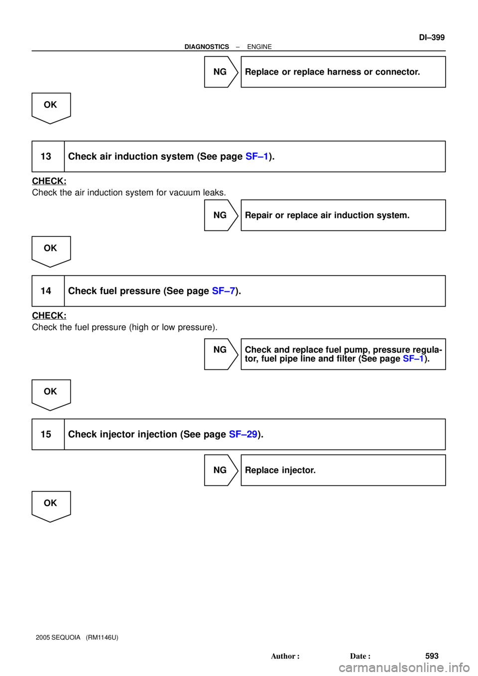
NG Replace or replace harness or connector.
OK
13 Check air induction system (See page SF±1).
CHECK:
Check the air induction system for vacuum leaks.
NG Repair or replace air induction system.
OK
14 Check fuel pressure (See page SF±7).
CHECK:
Check the fuel pressure (high or low pressure).
NG Check and replace fuel pump, pressure regula-
tor, fuel pipe line and filter (See page SF±1).
OK
15 Check injector injection (See page SF±29).
NG Replace injector.
OK
Page 602 of 4323
DI±400
± DIAGNOSTICSENGINE
594 Author�: Date�:
2005 SEQUOIA (RM1146U)
16 Replace air fuel ratio sensor.
NEXT
17 Perform confirmation driving pattern.
NEXT
18 Check whether DTC output recurs (DTC P2195, P2196, P2197 or P2198)
CHECK:
(a) On the hand±held tester, select the following menu items: DIAGNOSIS / ENHANCED OBD II / DTC
INFO / PENDING CODES.
(b) Read DTCs.
RESULT:
Display (DTC Output)Proceed To
P2195, P2196, P2197 or P2198A
No outputB
B Replace ECM (See page SF±80) and perform
confirmation driving pattern.
A
19 Confirm whether vehicle has run out of fuel in past.
NO Check for intermittent problems
(See page DI±11).
YES
DTC caused by running out of fuel.
Page 603 of 4323
± DIAGNOSTICSENGINE
DI±401
595 Author�: Date�:
2005 SEQUOIA (RM1146U)
20 Replace air fuel ratio sensor.
NEXT
21 Perform confirmation driving pattern.
NEXT
22 Check whether DTC output recurs (DTC P2195, P2196, P2197 or P2198)
CHECK:
(a) On the hand±held tester, select the following menu items: DIAGNOSIS / ENHANCED OBD II / DTC
INFO / PENDING CODES.
(b) Read DTCs.
RESULT:
Display (DTC Output)Proceed To
P2195, P2196, P2197 or P2198 (A/F sensor pending DTCs)A
No outputB
B Replace ECM (See page SF±80).
A
END
Page 604 of 4323

DTC P2238 Oxygen Sensor Pumping Current Circuit
Low (For A/F Sensor)(Bank 1 Sensor1)
DTC P2239 Oxygen Sensor Pumping Current C")
DI±402
± DIAGNOSTICSENGINE
596 Author�: Date�:
2005 SEQUOIA (RM1146U)
DTC P2238 Oxygen Sensor Pumping Current Circuit
Low (For A/F Sensor)(Bank 1 Sensor1)
DTC P2239 Oxygen Sensor Pumping Current Circuit
High (For A/F Sensor)(Bank 1 Sensor1)
DTC P2241 Oxygen Sensor Pumping Current Circuit
Low (For A/F Sensor)(Bank 2 Sensor1)
DTC P2242 Oxygen Sensor Pumping Current Circuit
High (For A/F Sensor)(Bank 2 Sensor1)
DTC P2252 Oxygen Sensor Reference Ground Circuit
Low (For A/F Sensor)(Bank 1 Sensor1)
DTC P2253 Oxygen Sensor Reference Ground Circuit
High (For A/F Sensor)(Bank 1 Sensor1)
DTC P2255 Oxygen Sensor Reference Ground Circuit
Low (For A/F Sensor)(Bank 2 Sensor1)
DTC P2256 Oxygen Sensor Reference Ground Circuit
High (For A/F Sensor)(Bank 2 Sensor1)
HINT:
�Although the DTC titles say oxygen sensor, these DTCs relate to the Air±Fuel Ratio (A/F) sensor.
�Sensor 1 refers to the sensor mounted in front of the Three±Way Catalytic Converter (TWC) and lo-
cated near the engine assembly.
DIDFU±01
Page 605 of 4323

CIRCUIT DESCRIPTION
Refer to DTC P2195 on page DI±383.
DTC No.DTC Detection ConditionsTrouble Areas
P2238
P2241
�Case 1:
Con")
± DIAGNOSTICSENGINE
DI±403
597 Author�: Date�:
2005 SEQUOIA (RM1146U)
CIRCUIT DESCRIPTION
Refer to DTC P2195 on page DI±383.
DTC No.DTC Detection ConditionsTrouble Areas
P2238
P2241
�Case 1:
Condition (a) or (b) continues for 5.0 seconds or more
(1 trip detection logic):
(a) AF+ voltage 0.5 V or less
(b) (AF+) ± (AF±) = 0.1 V or less
�Case 2:
A/F sensor admittance: Less than 0.022 1/W
(1 trip detection logic)
�Open or short in A/F sensor (sensor 1) circuit
�A/F sensor (sensor 1)
�A/F sensor heater
�EFI relay
�A/F sensor heater and relay circuits
�ECM
P2239
P2242AF+ voltage more than 4.5 V for 5.0 seconds or more
(1 trip detection logic)
�Open or short in A/F sensor (sensor 1) circuit
�A/F sensor (sensor 1)
�A/F sensor heater
�EFI relay
�A/F sensor heater and relay circuits
�ECM
P2252
P2255AF± voltage 0.5 V or less for 5.0 seconds or more
(1 trip detection logic)
�Open or short in A/F sensor (sensor 1) circuit
�A/F sensor (sensor 1)
�A/F sensor heater
�EFI relay
�A/F sensor heater and relay circuits
�ECM
P2253
P2256AF± voltage more than 4.5 V for 5.0 seconds or more
(1 trip detection logic)
�Open or short in A/F sensor (sensor 1) circuit
�A/F sensor (sensor 1)
�A/F sensor heater
�EFI relay
�A/F sensor heater and relay circuits
�ECM
MONITOR DESCRIPTION
The Air±Fuel Ratio (A/F) sensor varies its output voltage in proportion to the air±fuel ratio. If the A/F sensor
impedance (alternating current resistance) or voltage output deviates greatly from the standard range, the
ECM determines that there is an open or short malfunction in the A/F sensor circuit.