Page 598 of 1943

± SERVICE SPECIFICATIONSHYBRID TRANSAXLE
SS±23
145 Author�: Date�:
2001 PRIUS (RM778U) Counter driven gear preload adjusting shim thickness
Mark 1
Mark 2
Mark 3
Mark 50
Mark 51
Mark 52
Mark 53
Mark 54
Mark 55
Mark 56
Mark 57
Mark 58
Mark 59
Mark 60
Mark 61
Mark 62
Mark 63
Mark 64
Mark 65
Mark 66
Mark 67
Mark 68
Mark 69
Mark 70
Mark 18
Mark 19
Mark 20
Mark 21
Mark 22
1.25 mm (0.0492 in.)
1.28 mm (0.0504 in.)
1.31 mm (0.0516 in.)
1.34 mm (0.0528 in.)
1.36 mm (0.0535 in.)
1.38 mm (0.0543 in.)
1.40 mm (0.0551 in.)
1.42 mm (0.0559 in.)
1.44 mm (0.0567 in.)
1.46 mm (0.0575 in.)
1.48 mm (0.0583 in.)
1.50 mm (0.0591 in.)
1.52 mm (0.0598 in.)
1.54 mm (0.0606 in.)
1.56 mm (0.0614 in.)
1.58 mm (0.0622 in.)
1.60 mm (0.0630 in.)
1.62 mm (0.0638 in.)
1.64 mm (0.0646 in.)
1.66 mm (0.0654 in.)
1.68 mm (0.0661 in.)
1.70 mm (0.0669 in.)
1.72 mm (0.0677 in.)
1.74 mm (0.0685 in.)
1.76 mm (0.0693 in.)
1.79 mm (0.0705 in.)
1.82 mm (0.0717 in.)
1.85 mm (0.0728 in.)
1.88 mm (0.0740 in.)
Input shaft shim thickness
Mark 1
Mark 2
Mark 3
Mark 4
Mark 5
Mark 6
Mark 7
Mark 8
Mark 9
Mark 10
Mark 11
Mark 12
1.00 mm (0.0394 in.)
1.20 mm (0.0472 in.)
1.40 mm (0.0551 in.)
1.60 mm (0.0630 in.)
1.80 mm (0.0709 in.)
2.00 mm (0.0787 in.)
2.20 mm (0.0866 in.)
2.40 mm (0.0945 in.)
2.60 mm (0.1024 in.)
2.80 mm (0.1102 in.)
3.00 mm (0.1181 in.)
3.20 mm (0.1260 in.)
Counter drive gear shim thickness
Mark A
Mark B
Mark C
Mark D
Mark E
Mark F
Mark G
Mark H
Mark J
Mark K
Mark L
1.35 mm (0.0531 in.)
1.40 mm (0.0551 in.)
1.45 mm (0.0571 in.)
1.50 mm (0.0591 in.)
1.55 mm (0.0610 in.)
1.60 mm (0.0630 in.)
1.65 mm (0.0650 in.)
1.70 mm (0.0669 in.)
1.75 mm (0.0689 in.)
1.80 mm (0.0709 in.)
1.85 mm (0.0728 in.)
Differential oil seal LH and RH drive in depth2.7 ± 0.5 mm (0.11 ± 0.02 in.)
Oil pressure39.2 ± 78.4 kPa (0.4 ± 0.8 kgf/cm2, 5.7 ± 11.4 psi)
Page 618 of 1943
A04438A13924A14466
TC
CG
A14060
DI±10
± DIAGNOSTICSENGINE
2001 PRIUS (RM778U)
5 Check ignition timing.
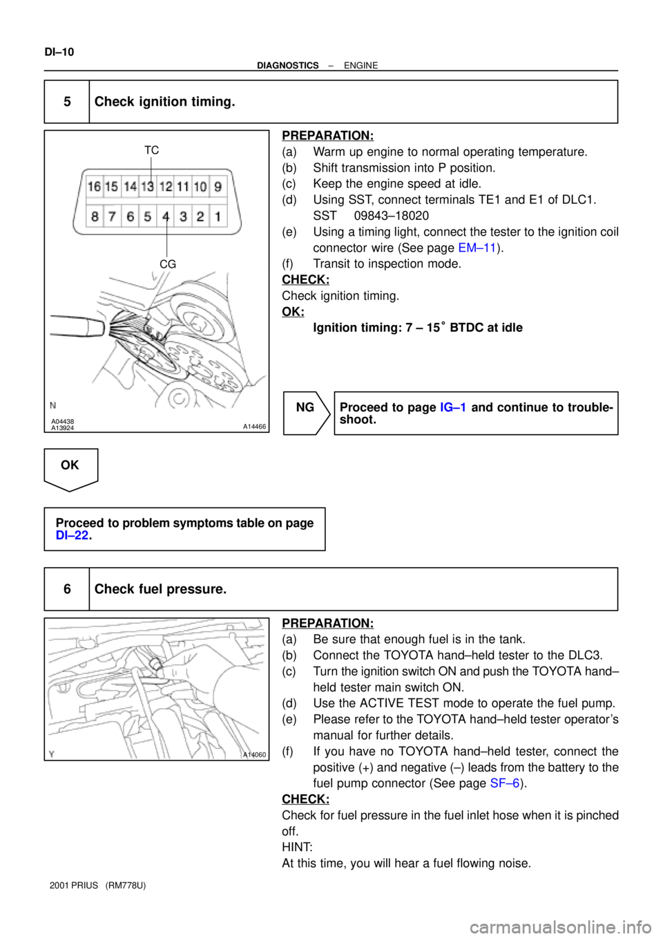
PREPARATION:
(a) Warm up engine to normal operating temperature.
(b) Shift transmission into P position.
(c) Keep the engine speed at idle.
(d) Using SST, connect terminals TE1 and E1 of DLC1.
SST 09843±18020
(e) Using a timing light, connect the tester to the ignition coil
connector wire (See page EM±11).
(f) Transit to inspection mode.
CHECK:
Check ignition timing.
OK:
Ignition timing: 7 ± 15° BTDC at idle
NG Proceed to page IG±1 and continue to trouble-
shoot.
OK
Proceed to problem symptoms table on page
DI±22.
6 Check fuel pressure.
PREPARATION:
(a) Be sure that enough fuel is in the tank.
(b) Connect the TOYOTA hand±held tester to the DLC3.
(c) Turn the ignition switch ON and push the TOYOTA hand±
held tester main switch ON.
(d) Use the ACTIVE TEST mode to operate the fuel pump.
(e) Please refer to the TOYOTA hand±held tester operator's
manual for further details.
(f) If you have no TOYOTA hand±held tester, connect the
positive (+) and negative (±) leads from the battery to the
fuel pump connector (See page SF±6).
CHECK:
Check for fuel pressure in the fuel inlet hose when it is pinched
off.
HINT:
At this time, you will hear a fuel flowing noise.
Page 721 of 1943
A09060
C2
Oil Control Valve
2 1Y±R
W±GECM
OCV+
OCV± 23
24
E7 E7
± DIAGNOSTICSENGINE
DI±121
2001 PRIUS (RM778U)
DTC P1349 VVT System Malfunction
CIRCUIT DESCRIPTION
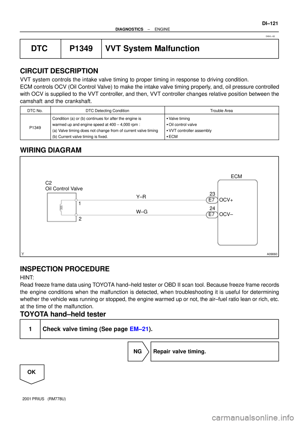
VVT system controls the intake valve timing to proper timing in response to driving condition.
ECM controls OCV (Oil Control Valve) to make the intake valve timing properly, and, oil pressure controlled
with OCV is supplied to the VVT controller, and then, VVT controller changes relative position between the
camshaft and the crankshaft.
DTC No.DTC Detecting ConditionTrouble Area
P1349
Condition (a) or (b) continues for after the engine is
warmed up and engine speed at 400 ± 4,000 rpm :
(a) Valve timing does not change from of current valve timing
(b) Current valve timing is fixed.�Valve timing
�Oil control valve
�VVT controller assembly
�ECM
WIRING DIAGRAM
INSPECTION PROCEDURE
HINT:
Read freeze frame data using TOYOTA hand±held tester or OBD II scan tool. Because freeze frame records
the engine conditions when the malfunction is detected, when troubleshooting it is useful for determining
whether the vehicle was running or stopped, the engine warmed up or not, the air±fuel ratio lean or rich, etc.
at the time of the malfunction.
TOYOTA hand±held tester
1 Check valve timing (See page EM±21).
NG Repair valve timing.
OK
DI6VL±02
Page 791 of 1943

DI±194
± DIAGNOSTICSHYBRID VEHICLE CONTROL SYSTEM
2001 PRIUS (RM778U)
0: When engine is stopped
1: When stopping engine
2: When starting engine
DRIVE CONDITION3: When cranking engine or engine is operatingDRIVE CONDITION
4: While generating power or load driving
5: ±
6: While racing engine in P position
DRIVING PATTEN1History of driving pattern 1
DRIVING PATTEN2History of driving pattern 2
DRIVING PATTEN3History of driving pattern 3
DRIVING PATTERNHIstory of driving
ECU TYPEECU type
ENG INDPDET RQFactors causing engine to run independently
ENG STOP RQSTEngine stop request
ENG STP INHIBITEngine stop inhibition
ENG WARM UP RQTEngine warming up request
ENGINE FUEL CUTEngine fuel cut
ENGINE SPDEngine speed
EXCLUSIVE INFO1Exclusive information 1
EXCLUSIVE INFO2Exclusive information 2
EXCLUSIVE INFO3Exclusive information 3
EXCLUSIVE INFO4Exclusive information 4
EXCLUSIVE INFO5Exclusive information 5
EXCLUSIVE INFO6Exclusive information 6
FUEL SHORTAGELow fuel
HCAC ABSRT RQSTHCAC OBD request
HV BATT CH RQSTRequest from HV ECU to charge the battery
HV ECU INTERMITTENTHV ECU intermittent problems
IDLING REQUESTEngine idling request
IG OFF IN DRVINTurning IG OFF while driving the car
IG OFF TIMEIG OFF time
ILK OPERATIONInterlock operation
INFORMATION 1±5Information code
INPUT V LOWInput voltage is too low
INPUT V OVERInput voltage is too high
INTAKE AIRIntake air temperature
INVERT TEMP±MG1Temperature of inverter MG1
INVERT TEMP±MG2Temperature of inverter MG2
LATEST OPERLatest number of operation
LATEST TRIPLatest number of trips (IG ON±OFF)
LOAD CONDITIONIndicating which of MG1 or MG2 the vehicle uses more
MAIN BATT LOWSOC of main battery becomes low
MCYL CTRL POWERTorque for controlling oil pressure of master cylinder
MG1 TEMP HIGHTemperature MG1 is too high
MG2 TEMP HIGHTemperature MG2 is too high
MG1 CURRENT VElectric current of MG1 V phase
Page 998 of 1943

± DIAGNOSTICSANTI±LOCK BRAKE SYSTEM WITH EBD & RBS
DI±421
2001 PRIUS (RM778U)
DTC C1253/53 Hydro Motor Relay Circuit
CIRCUIT DESCRIPTION
The hydro motor relay supplies power to the hydraulic brake booster pump motor. While the ABS & EBD &
RBS are activated, the ECU switches the motor relay ON and operates the hydraulic brake booster pump
motor.
DTC No.DTC Detecting ConditionTrouble Area
C1253/53
When any of the following 1. through 4. is detected:
1. After turning the ignition switch ON, open in the relay
coil is detected for more than 1 sec.
2. When the pressure switch does not control motor
driving, the status that the motor relay is always ON
continues for more than 1 sec. due to short circuit.
3. When the pressure switch (PH) detects the low
pressure or while the pump motor operates to increase
the pressure, the status that the motor relay does not
turn ON continues for more than 0.2 sec.
4. When pressure switch does not control motor driving,
the status that the motor relay is always ON due to the
welded contact continues for more than 2 sec.
�Hydro motor relay
�Hydro motor relay circuit
DI29A±13
Page 1225 of 1943
DI±682
± DIAGNOSTICSCOMBINATION METER SYSTEM
2001 PRIUS (RM778U)
4 Check the corresponding switch or ECU.
CHECK:
Check if the corresponding switch or ECU is normal or not.
Ye s
No Corresponding switch or ECU faulty.
Combination meter ECU faulty.
*:
Multiplex communication inputSingle Communication Input
OPEN DOOR WARNINGHI±BEAM INDICATOR
BRAKE WARNINGTURN SIGNAL IND
OUTPUT CONTROL INDICATORSRS WARNING
SHIFT POSITION INDICATORABS WARNING
SEAT BELT WARNINGCHECK ENGINE WARNING
READY INDICATOR
WATER TEMPERATURE WARNING
OIL PRESSURE WARNING
CRUISE CONTROL INDICATOR
TAIL INDICATOR
DISCHARGE WARNING
Page 1466 of 1943
EM1IT±02
F12396
TOYOTA Hand±held
Tester
DLC3
A13923
± ENGINE MECHANICALCOMPRESSION
EM±3
111 9 Author�: Date�:
2001 PRIUS (RM778U)
COMPRESSION
INSPECTION
HINT:
If there is lack of power, excessive oil consumption or poor fuel
economy, measure the compression pressure.
NOTICE:
The measurement of compression pressure should be per-
formed in the Cranking Mode.
1. WARM UP AND STOP ENGINE
Allow the engine to warm up to normal operating temperature.
2. REMOVE AIR CLEANER ASSEMBLY
3. REMOVE IGNITION COIL (See page IG±6)
4. REMOVE SPARK PLUGS
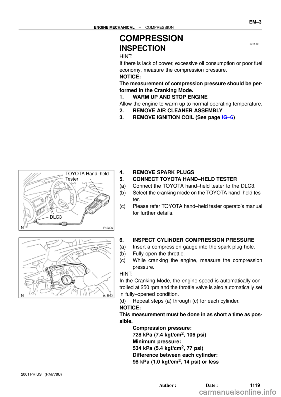
5. CONNECT TOYOTA HAND±HELD TESTER
(a) Connect the TOYOTA hand±held tester to the DLC3.
(b) Select the cranking mode on the TOYOTA hand±held tes-
ter.
(c) Please refer TOYOTA hand±held tester operato's manual
for further details.
6. INSPECT CYLINDER COMPRESSION PRESSURE
(a) Insert a compression gauge into the spark plug hole.
(b) Fully open the throttle.
(c) While cranking the engine, measure the compression
pressure.
HINT:
In the Cranking Mode, the engine speed is automatically con-
trolled at 250 rpm and the throttle valve is also automatically set
in fully±opened condition.
(d) Repeat steps (a) through (c) for each cylinder.
NOTICE:
This measurement must be done in as short a time as pos-
sible.
Compression pressure:
728 kPa (7.4 kgf/cm
2, 106 psi)
Minimum pressure:
534 kPa (5.4 kgf/cm
2, 77 psi)
Difference between each cylinder:
98 kPa (1.0 kgf/cm
2, 14 psi) or less
Page 1467 of 1943
EM±4
± ENGINE MECHANICALCOMPRESSION
1120 Author�: Date�:
2001 PRIUS (RM778U)
(e) If the cylinder compression in one more cylinders is low,
pour a small amount of engine oil into the cylinder through
the spark plug hole and repeat steps (a) through (c) for
cylinders with low compression.
�If adding oil helps the compression, it is likely that
the piston rings and/or cylinder bore are worn or
damaged.
�If pressure stays low, a valve may be sticking or
seating is improper, or there may be leakage past
the gasket.
7. REINSTALL SPARK PLUGS
8. REINSTALL IGNITION COIL (See page IG±7)