Page 406 of 1943

BODY ELECTRICAL ± LIGHTING
151LBE68151LBE67
Multi-Reflector Type HeadlightConventional Headlight Reflector
(Multiple Parabolic Shape)
Headlight Bulb
Headlight Bulb
Lens
Light DistributionReflector
(Rotating Parabolic Shape)
Headlight Bulb
Lens Cut
Lens
Light Distribution
182BE03
From
BatteryDimmer Relay
Headlight
Relay
Parking
Brake Switch
H-LP DIM
PKBDaytime
Running
Light Relay
DRL
From
BatteryEH
HILO HI
LO
No.4
Daytime
Running
Light Relay
144
LIGHTING
�HEADLIGHTS
The prius has newly adopted the multi-reflector headlights. Conventional headlights accomplish the dispersion
and distribution of the light that is emitted by the bulbs through the lens cut pattern. However, with the multi-reflec-
tor type headlights, the light from the bulbs is dispersed and distributed through multiple parabolic shaped reflec-
tors. As a result, the lens cut pattern is no longer provided in the center of the lens, thus realizing a clear look.
� Light Distribution Diagram �
�DAYTIME RUNNING LIGHT SYSTEM
The daytime running light system is adopted for Canada model as standard and U.S.A. model as optional
equipment. This system is designed to automatically activate the headlights (dimmed low beams) during the
daytime to keep the car highly visible to other vehicles.
This system is controlled by a semi-conductor relay circuit (daytime running light relay).
Page 1238 of 1943

I15484
2 3 66
8 7
1 4 2
1
4
3 2 1 1
11
1
710
883
A L D
FE
E
E
LE
ER±L
R±G
R±W
R±G R±W R±W R±W
R±G
R±G B±G
R±G B
F13 F12
2I
2A 1B1F
1F
1F3
ID2 IA2J20
J/C
IA1
J4J5
ID 2K 2A
15
17
BatteryC10 High Beam
Indicator Light
(Comb. meter) F18
FL Block No. 2
J11
J/CJ4 H2
Headlight RH
10A HEAD (LH) 10A HEAD (RH)
Short Pin HEAD RelayEngine Room J/BB9
Body ECU
Short Pin
120A MAIN
Instrument
Panel J/BJ12 J13
W±B
H1
Headlight
LH
1
FL Block No. 13
1
HRLY
Instrument
Panel J/B DI±698
± DIAGNOSTICSBODY CONTROL SYSTEM
2001 PRIUS (RM778U)
Headlight Relay Circuit
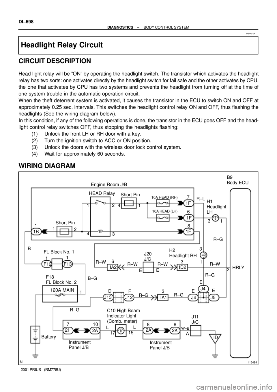
CIRCUIT DESCRIPTION
Head light relay will be ºONº by operating the headlight switch. The transistor which activates the headlight
relay has two sorts: one activates directly by the headlight switch for fail safe and the other activates by CPU.
the one that activates by CPU has two systems and prevents the headlight from turning off at the time of
one system trouble in the automatic operation circuit.
When the theft deterrent system is activated, it causes the transistor in the ECU to switch ON and OFF at
approximately 0.25 sec. intervals. This switches the headlight control relay ON and OFF, thus flashing the
headlights (See the wiring diagram below).
In this condition, if any of the following operations is done, the transistor in the ECU goes OFF and the head-
light control relay switches OFF, thus stopping the headlights flashing:
(1) Unlock the front LH or RH door with a key.
(2) Turn the ignition switch to ACC or ON position.
(3) Unlock the doors with the wireless door lock control system.
(4) Wait for approximately 60 seconds.
WIRING DIAGRAM
DI5VQ±04
Page 1764 of 1943

± BODY ELECTRICALTROUBLESHOOTING
BE±7
1674 Author�: Date�:
2001 PRIUS (RM778U)
Warning Lights:
COMBINATION METER
SymptomSuspect AreaSee page
Warning light do not light up. (Except Discharge, Open Door and
SRS)
1. GAUGE Fuse
2. Meter Circuit Plate
3. DC/DC converter
4. Wire Harness±
BE±39
±
±
Fuel Level warning light does not light up.
1. Bulb
2. Meter Circuit Plate
3. Fuel Tank Assembly
4. Wire Harness±
BE±39
±
±
Low Oil Pressure warning light does not light up.
1. Bulb
2. Low Oil Pressure Warning Switch
3. Meter Circuit Plate
4. Wire Harness±
BE±42
BE±39
±
ABS warning light does not light up.
1. Bulb
2. ABS ECU
3. Wire Harness±
DI±351
±
Seat Belt warning light does not light up.
1. Bulb
2. Buckle Switch
3. Meter Circuit
4. Wire Harness±
BE±42
BE±42
±
Brake warning light does not light up.
1. Bulb
2. Parking Brake Switch
3. Brake Fluid Level Warning Switch
4. Meter Circuit Plate
5. Wire Harness±
BE±42
BE±42
BE±39
±
SRS Warning light does not light up.
1. Bulb
2. Airbag Sensor Assembly
3. Meter Circuit Plate
4. Wire Harness±
DI±495
BE±39
±
Open Door warning light does not light up.
1. DOME Fuse
2. Bulb
3. Door Courtesy Switch
4. Meter Circuit Plate
5. Wire Harness±
±
BE±27
BE±39
±
Indicator Lights:
COMBINATION METER
SymptomSuspect AreaSee page
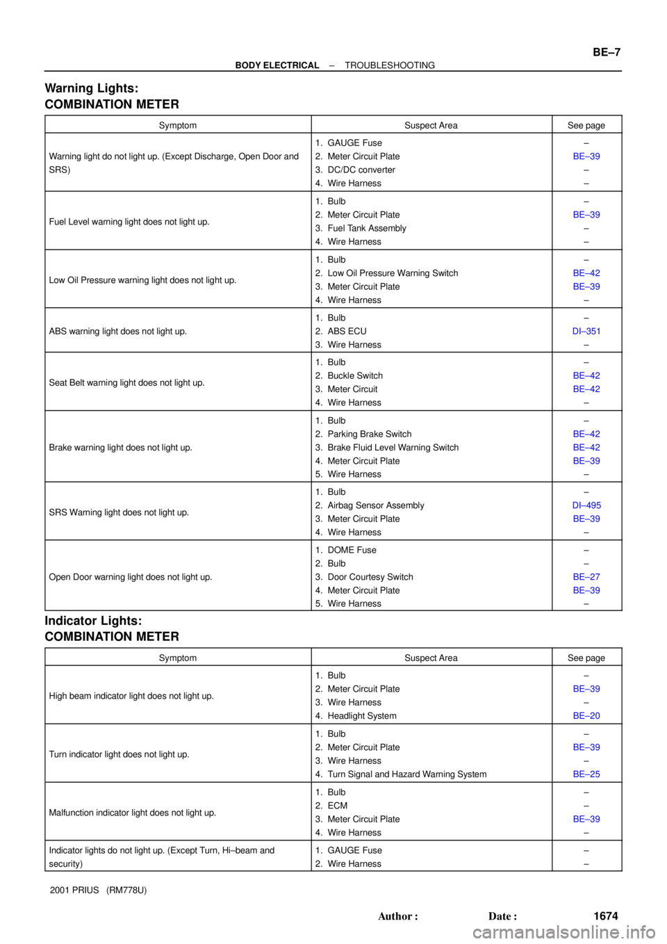
High beam indicator light does not light up.
1. Bulb
2. Meter Circuit Plate
3. Wire Harness
4. Headlight System±
BE±39
±
BE±20
Turn indicator light does not light up.
1. Bulb
2. Meter Circuit Plate
3. Wire Harness
4. Turn Signal and Hazard Warning System±
BE±39
±
BE±25
Malfunction indicator light does not light up.
1. Bulb
2. ECM
3. Meter Circuit Plate
4. Wire Harness±
±
BE±39
±
Indicator lights do not light up. (Except Turn, Hi±beam and
security)1. GAUGE Fuse
2. Wire Harness±
±
Page 1773 of 1943

BE1UX±02
I14295
7
8
13
14 16
17
HI
Flash OFFTAIL HEAD LO
Z05930
1
2
31
55 3
2
N14863
12
35
12 35
Z05930
1
2
351
2 3
5 BE±20
± BODY ELECTRICALHEADLIGHT AND TAILLIGHT SYSTEM
2001 PRIUS (RM778U)
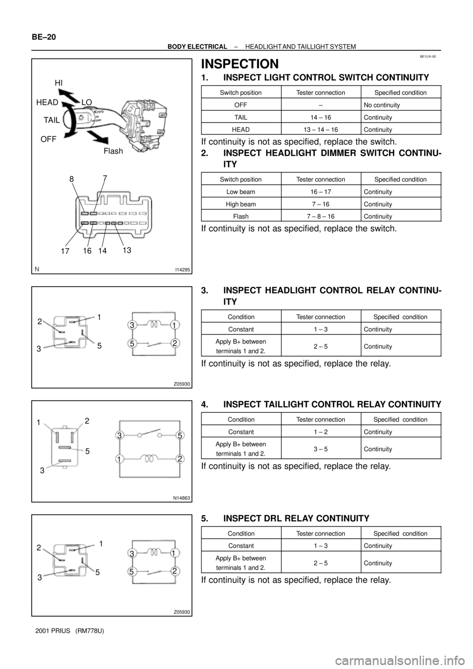
INSPECTION
1. INSPECT LIGHT CONTROL SWITCH CONTINUITY
Switch positionTester connectionSpecified condition
OFF±No continuity
TAIL14 ± 16Continuity
HEAD13 ± 14 ± 16Continuity
If continuity is not as specified, replace the switch.
2. INSPECT HEADLIGHT DIMMER SWITCH CONTINU-
ITY
Switch positionTester connectionSpecified condition
Low beam16 ± 17Continuity
High beam7 ± 16Continuity
Flash7 ± 8 ± 16Continuity
If continuity is not as specified, replace the switch.
3. INSPECT HEADLIGHT CONTROL RELAY CONTINU-
ITY
ConditionTester connectionSpecified condition
Constant1 ± 3Continuity
Apply B+ between
terminals 1 and 2.2 ± 5Continuity
If continuity is not as specified, replace the relay.
4. INSPECT TAILLIGHT CONTROL RELAY CONTINUITY
ConditionTester connectionSpecified condition
Constant1 ± 2Continuity
Apply B+ between
terminals 1 and 2.3 ± 5Continuity
If continuity is not as specified, replace the relay.
5. INSPECT DRL RELAY CONTINUITY
ConditionTester connectionSpecified condition
Constant1 ± 3Continuity
Apply B+ between
terminals 1 and 2.2 ± 5Continuity
If continuity is not as specified, replace the relay.
Page 1776 of 1943

I17791
0.4 °
3 m (9.84 ft) H 29.7 mm
(1.17 in.)
7
V RH Line
W90 °
V LH Line4
Low Beam:
V LH LineV Line V RH Line 65
6
29.7 mm
(1.17 in.)
High Beam:
V LH LineV Line V RH Line 6
5629.7 mm
(1.17 in.)
29.7 mm
(1.17 in.) H 4
O: step No.
7
H4
W
W
± BODY ELECTRICALHEADLIGHT AND TAILLIGHT SYSTEM
BE±23
2001 PRIUS (RM778U)
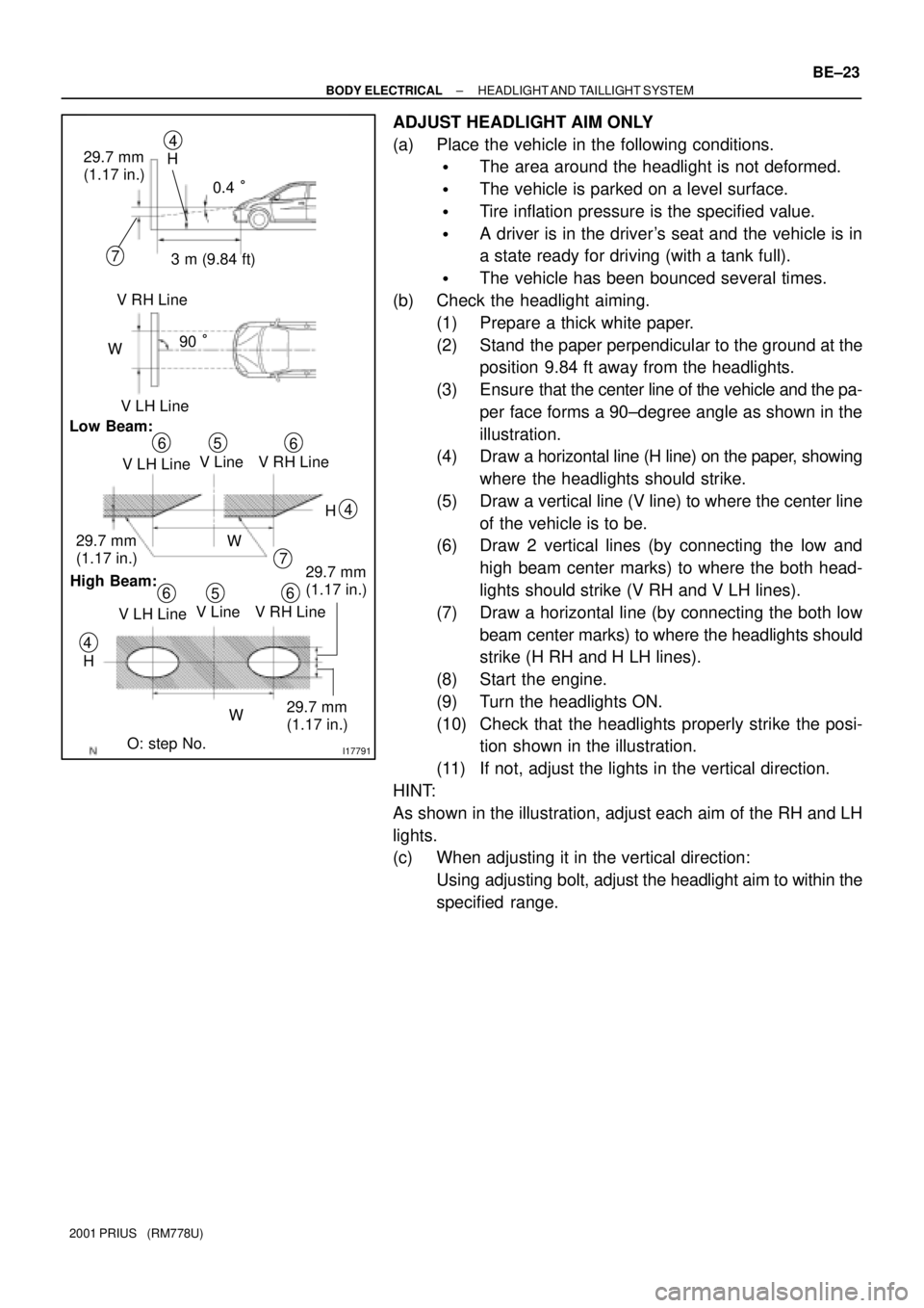
ADJUST HEADLIGHT AIM ONLY
(a) Place the vehicle in the following conditions.
�The area around the headlight is not deformed.
�The vehicle is parked on a level surface.
�Tire inflation pressure is the specified value.
�A driver is in the driver's seat and the vehicle is in
a state ready for driving (with a tank full).
�The vehicle has been bounced several times.
(b) Check the headlight aiming.
(1) Prepare a thick white paper.
(2) Stand the paper perpendicular to the ground at the
position 9.84 ft away from the headlights.
(3) Ensure that the center line of the vehicle and the pa-
per face forms a 90±degree angle as shown in the
illustration.
(4) Draw a horizontal line (H line) on the paper, showing
where the headlights should strike.
(5) Draw a vertical line (V line) to where the center line
of the vehicle is to be.
(6) Draw 2 vertical lines (by connecting the low and
high beam center marks) to where the both head-
lights should strike (V RH and V LH lines).
(7) Draw a horizontal line (by connecting the both low
beam center marks) to where the headlights should
strike (H RH and H LH lines).
(8) Start the engine.
(9) Turn the headlights ON.
(10) Check that the headlights properly strike the posi-
tion shown in the illustration.
(11) If not, adjust the lights in the vertical direction.
HINT:
As shown in the illustration, adjust each aim of the RH and LH
lights.
(c) When adjusting it in the vertical direction:
Using adjusting bolt, adjust the headlight aim to within the
specified range.
Page 1785 of 1943
I17798
A20
A12
A14
A2
A3
A1
B7
B6
B1
A9
A11
A13
A22
A21
B2
B3Conversion
Drive unit
Correspon
dence
Buzzer
Power Supply
Circuit (VFD)
ECU
Drive unit
Open door indicator
Illumination
Brake warning
Driver seat belt warning
Low oil pressure warning
Discharge warning
CRUISE main indicator
Engine coolant warning (Low)
Engine coolant warning (High)
Passenger seat belt warning
Malfunction indicator
ABS warning
SRS warning
Left turn indicator
Right turn indicator
Hi±beam indicator B5
A19
A18
A17A15 A16 A10 B4 Output control indicator BE±40
± BODY ELECTRICALCOMBINATION METER
2001 PRIUS (RM778U)