Page 691 of 2572
'05 HIGHLANDER_U (L/O 0409)
389
2005 HIGHLANDER from Nov. '04 Prod. (OM48570U)
REPLACING YOUR TIRES
When replacing a tire, use a tire of
the same size and construction,
and the same or greater maximum
load as the originally installed
tires. Also, on four- wheel drive
models, all the tires must be the
same brand and have the same
tread patterns.
Using any other size or type of tire
may seriously affect handling, ride,
speedometer/odometer calibration,
ground clearance, and clearance be-
tween the body and tires or snow
chains.
Check that the maximum load of the
replaced tire is greater than 1/2 of the
Gross Axle Weight Ratings (GAWR)
of either the front axle or the rear
axle, whichever is greater. As for the
maximum load of the tire, see the load
limit at maximum cold tire inflation
pressure mentioned on the sidewall
of the tire, and as for the Gross Axle
Weight Ratings (GAWR), see the Cer-
tification Label.For details about the side wall of the
tire and the Certification Label, see
pages 301 and 304.
CAUTION
Observe the following instruc-
tions. Otherwise, an accident
may occur resulting in death or
serious injuries.
�Do not mix radial, bias belted,
or bias- ply tires on your ve-
hicle, as this may cause dan-
gerous handling characteris-
tics resulting in loss of control.
�Do not use tires other than the
manufacturer's recommended
size, as this may cause danger-
ous handling characteristics
resulting in loss of control.
�Four- wheel drive models:
Do not use tires of different
brands, sizes, construction or
tread patterns, as this may
cause dangerous handling
characteristics resulting in
loss of control.
Toyota recommends all four tires,
or at least both of the front or rear
tires be replaced at a time as a set.
See If you have a flat tireº on page
337 in Section 4 for tire change proce-
dure.
When a tire is replaced, the wheel
should always be balanced.
An unbalanced wheel may affect ve-
hicle handling and tire life. Wheels
can get out of balance with regular
use and should therefore be balanced
occasionally.
When replacing a tubeless tire, the
air valve should also be replaced
with a new one.
Page 692 of 2572
'05 HIGHLANDER_U (L/O 0409)
390
2005 HIGHLANDER from Nov. '04 Prod. (OM48570U)
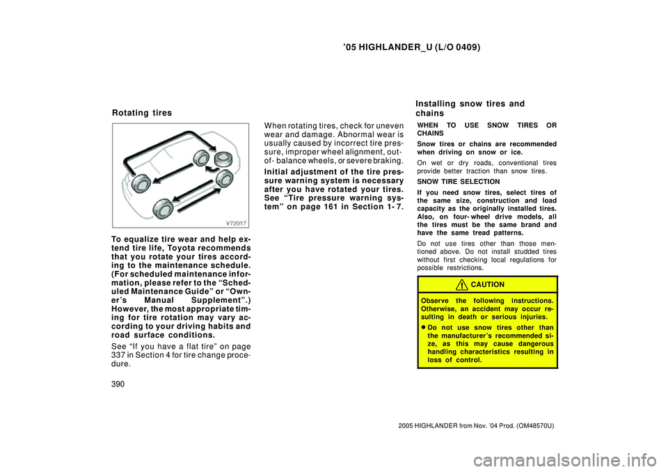
To equalize tire wear and help ex-
tend tire life, Toyota recommends
that you rotate your tires accord-
ing to the maintenance schedule.
(For scheduled maintenance infor-
mation, please refer to the Sched-
uled Maintenance Guideº or Own-
er's Manual Supplementº.)
However, the most appropriate tim-
ing for tire rotation may vary ac-
cording to your driving habits and
road surface conditions.
See If you have a flat tireº on page
337 in Section 4 for tire change proce-
dure.When rotating tires, check for uneven
wear and damage. Abnormal wear is
usually caused by incorrect tire pres-
sure, improper wheel alignment, out-
of- balance wheels, or severe braking.
Initial adjustment of the tire pres-
sure warning system is necessary
after you have rotated your tires.
See Tire pressure warning sys-
temº on page 161 in Section 1- 7.
WHEN TO USE SNOW TIRES OR
CHAINS
Snow tires or chains are recommended
when driving on snow or ice.
On wet or dry roads, conventional tires
provide better traction than snow tires.
SNOW TIRE SELECTION
If you need snow tires, select tires of
the same size, construction and load
capacity as the originally installed tires.
Also, on four- wheel drive models, all
the tires must be the same brand and
have the same tread patterns.
Do not use tires other than those men-
tioned above. Do not install studded tires
without first checking local regulations for
possible restrictions.
CAUTION
Observe the following instructions.
Otherwise, an accident may occur re-
sulting in death or serious injuries.
�Do not use snow tires other than
the manufacturer 's recommended si-
ze, as this may cause dangerous
handling characteristics resulting in
loss of control.
Rotating tiresInstalling snow tires and
chains
Page 854 of 2572
F46778
ECM S27
Skid Control ECU
With Actuator
A1
A/C Ambient Temp.
SensorENG+
TA M
E2 IC4
IK3V
W-L
E524
Short Connector
S28 EB2ENG-
E5
E6
E7 R
B30
32 IC4
28 5
18
5 W-G
B-R ENG+
ENG-9
23
6
S29 55
BRBRBR
1 2
05-756
- DIAGNOSTICSTIRE PRESSURE WARNING SYSTEM
946 Author�: Date�:
2005 HIGHLANDER REPAIR MANUAL (RM1144U)
AMBIENT TEMPERATURE SENSOR CIRCUIT
CIRCUIT DESCRIPTION
The ambient temperature sensor sends the outside temperature signal to the ECM. The ECM transmits the
signal to the skid control ECU as a communication signal. The skid control ECU controls the tire pressure
warning system, depending on the changes of the outside temperature.
HINT:
The signal sent from the ambient temperature sensor is also used in the A/C.
WIRING DIAGRAM
INSPECTION PROCEDURE
1 CHECK DIAGNOSTIC CODE OUTPUT
(a) Check if the normal code is output by air conditioning system (see page 05-1 117).
OK:
DTC is not output.
NG REPAIR CIRCUIT INDICATED BY OUTPUT
CODE
OK
05IP2-01
Page 855 of 2572
F45165F45562F45563
Wire Harness Side:
Wire Harness Side:
ENG-ENG+ENG+
ENG- S27
E5
- DIAGNOSTICSTIRE PRESSURE WARNING SYSTEM
05-757
947 Author�: Date�:
2005 HIGHLANDER REPAIR MANUAL (RM1144U)
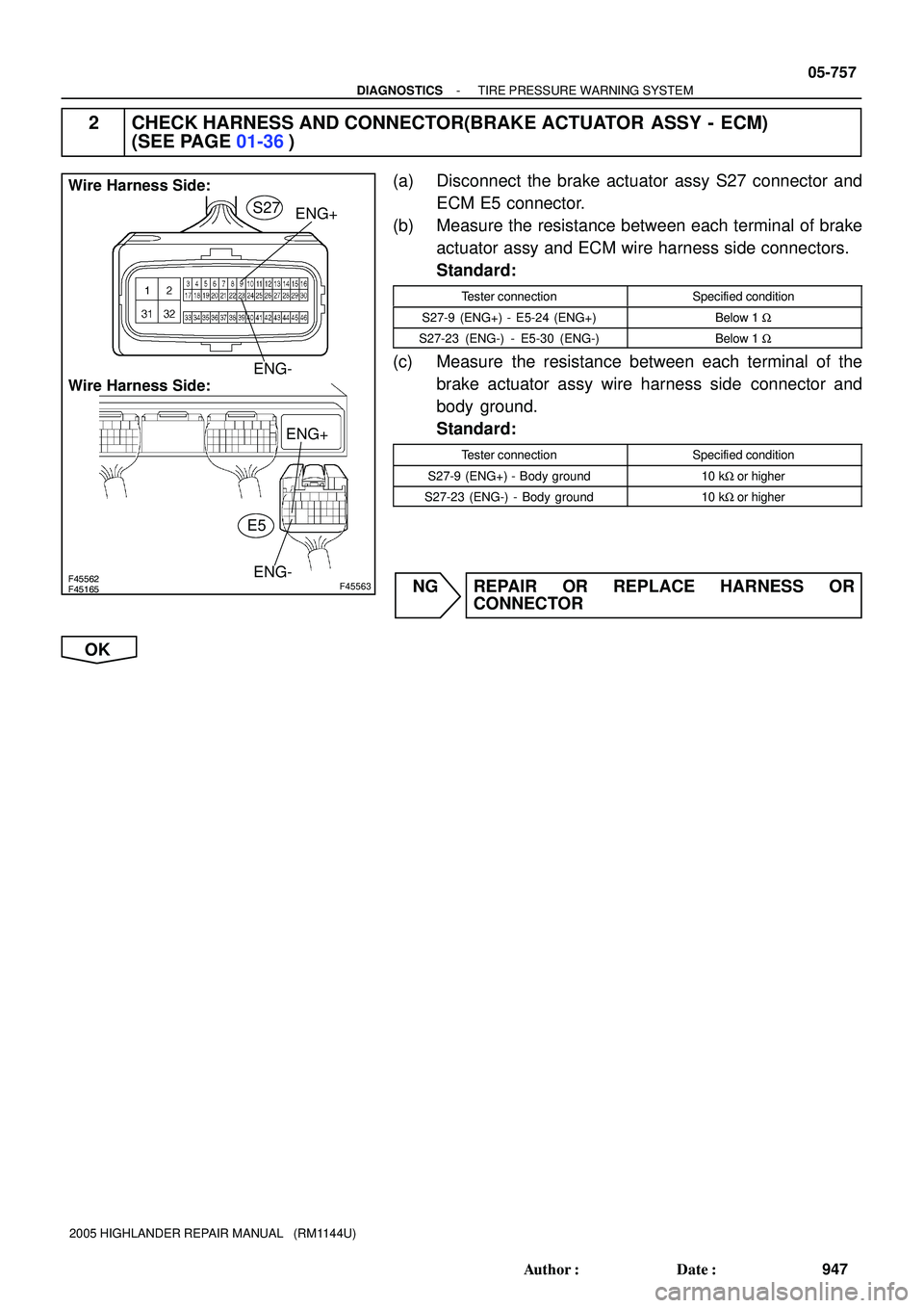
2 CHECK HARNESS AND CONNECTOR(BRAKE ACTUATOR ASSY - ECM)
(SEE PAGE 01-36)
(a) Disconnect the brake actuator assy S27 connector and
ECM E5 connector.
(b) Measure the resistance between each terminal of brake
actuator assy and ECM wire harness side connectors.
Standard:
Tester connectionSpecified condition
S27-9 (ENG+) - E5-24 (ENG+)Below 1 W
S27-23 (ENG-) - E5-30 (ENG-)Below 1 W
(c) Measure the resistance between each terminal of the
brake actuator assy wire harness side connector and
body ground.
Standard:
Tester connectionSpecified condition
S27-9 (ENG+) - Body ground10 kW or higher
S27-23 (ENG-) - Body ground10 kW or higher
NG REPAIR OR REPLACE HARNESS OR
CONNECTOR
OK
Page 856 of 2572
A53769
ENG- ENG+
E5
E9
E1 ECM:
F45157
GND
1 V / Division
0.5 ms / Division
Normal Signal Waveform: ENG + terminal
F45158
1 V / Division
0.5 ms / Division
Normal Signal Waveform: ENG- terminal
GND
05-758
- DIAGNOSTICSTIRE PRESSURE WARNING SYSTEM
948 Author�: Date�:
2005 HIGHLANDER REPAIR MANUAL (RM1144U)
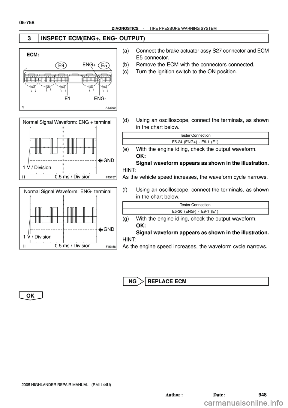
3 INSPECT ECM(ENG+, ENG- OUTPUT)
(a) Connect the brake actuator assy S27 connector and ECM
E5 connector.
(b) Remove the ECM with the connectors connected.
(c) Turn the ignition switch to the ON position.
(d) Using an oscilloscope, connect the terminals, as shown
in the chart below.
Tester Connection
E5-24 (ENG+) - E9-1 (E1)
(e) With the engine idling, check the output waveform.
OK:
Signal waveform appears as shown in the illustration.
HINT:
As the vehicle speed increases, the waveform cycle narrows.
(f) Using an oscilloscope, connect the terminals, as shown
in the chart below.
Tester Connection
E5-30 (ENG-) - E9-1 (E1)
(g) With the engine idling, check the output waveform.
OK:
Signal waveform appears as shown in the illustration.
HINT:
As the engine speed increases, the waveform cycle narrows.
NG REPLACE ECM
OK
Page 857 of 2572

I30155
Ambient Temperature Sensor:
A1
I38777
Temperature (�C) 3.5
3.0
2.5
2.0
1.5
1.0
5.0
0.0
40 0
20 60 Resistance
(kW)4.0
�C
�F 104 68 140MIX
MAX
- DIAGNOSTICSTIRE PRESSURE WARNING SYSTEM
05-759
949 Author�: Date�:
2005 HIGHLANDER REPAIR MANUAL (RM1144U)
4 INSPECT AMBIENT TEMPERATURE SENSOR
(a) Remove the ambient temperature sensor and disconnect
the A1 connector.
(b) Measure the resistance according to the value(s) in the
table below.
Standard:
Tester connectionConditionSpecified condition
A1-1 - A1-250�F (10�C)3.00 to 3.73 kW
A1-1 - A1-259�F (15�C)2.45 to 2.88 kW
A1-1 - A1-268�F (20�C)1.95 to 2.30 kW
A1-1 - A1-277�F (25�C)1.60 to 1.80 kW
A1-1 - A1-286�F (30�C)1.28 to 1.47 kW
A1-1 - A1-295�F (35�C)1.00 to 1.22 kW
A1-1 - A1-2104�F (40�C)0.80 to 1.00 kW
A1-1 - A1-211 3�F (45�C)0.65 to 0.85 kW
A1-1 - A1-2122�F (50�C)0.50 to 0.70 kW
A1-1 - A1-2131�F (55�C)0.44 to 0.60 kW
A1-1 - A1-2140�F (60�C)0.36 to 0.50 kW
HINT:
As the temperature increases, the resistance decreases (see
the chart below).
NOTICE:
Even slightly touching the sensor may change the resis-
tance value. Be sure to hold the connector of the sensor.
NG REPLACE AMBIENT TEMPERATURE SENSOR
OK
Page 858 of 2572
F46780
A1
Wire harness side:
E7
Wire harness side:
E2
TA ME6
05-760
- DIAGNOSTICSTIRE PRESSURE WARNING SYSTEM
950 Author�: Date�:
2005 HIGHLANDER REPAIR MANUAL (RM1144U)
5 CHECK HARNESS AND CONNECTOR(ECM - AMBIENT TEMPERATURE SENSOR)
(SEE PAGE 01-36)
(a) Disconnect the ECM E6 and E7 connectors.
(b) Measure the resistance according to the value(s) in the
table below.
Standard:
Tester connectionConditionSpecified condition
E6-32 (TAM) - A1-2AlwaysBelow 1 W
E7-28 (E2) - A1-1AlwaysBelow 1 W
E6-32 (TAM) - Body
groundAlways10 kW or higher
E7-28 (E2) - Body
groundAlways10 kW or higher
NG REPAIR OR REPLACE HARNESS OR
CONNECTOR
OK
REPLACE ECM (SEE PAGE 10-9 OR 10-24)
Page 1511 of 2572
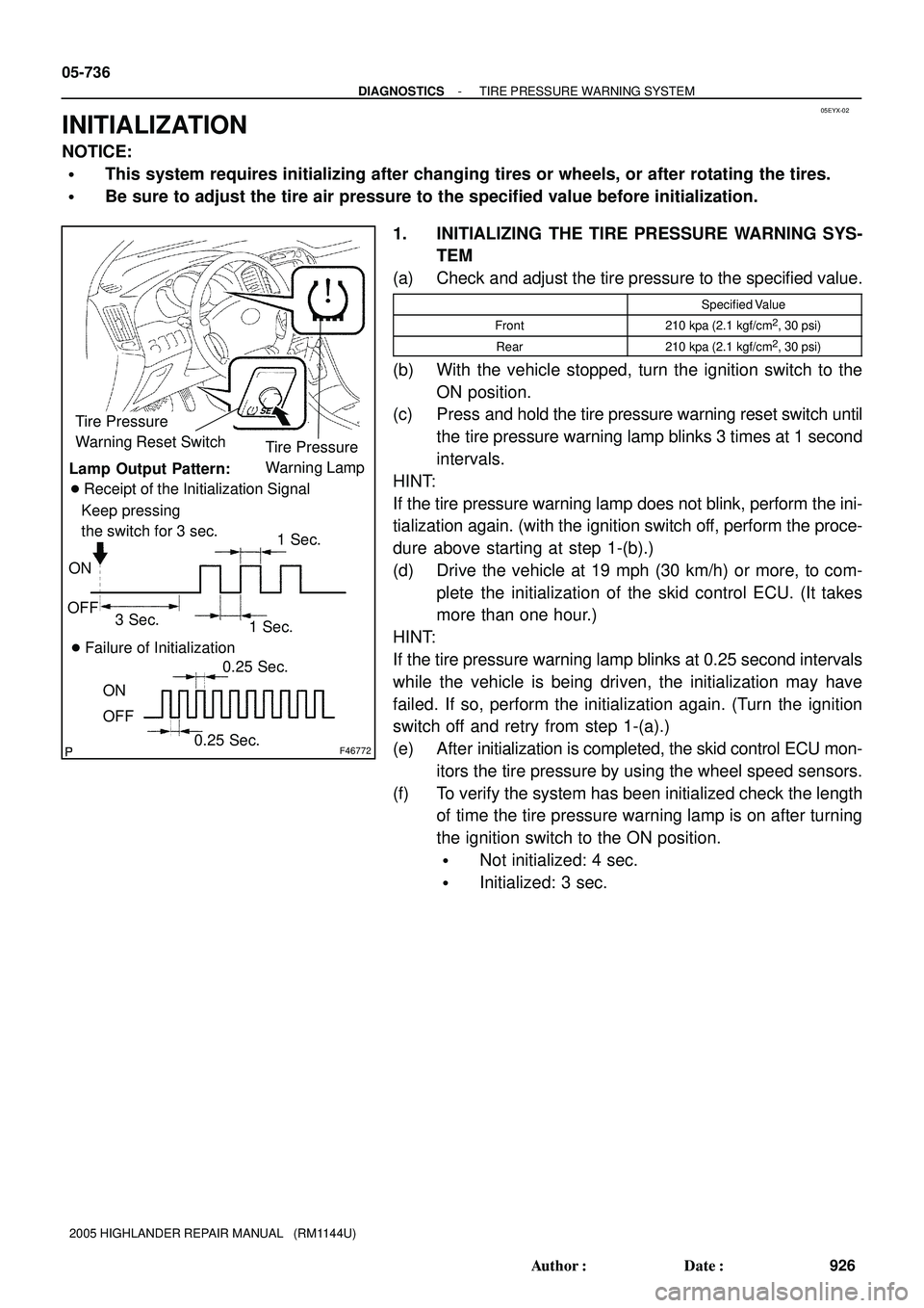
05EYX-02
F46772
Tire Pressure
Warning Reset Switch
Tire Pressure
Warning Lamp
Lamp Output Pattern:
� Receipt of the Initialization Signal
Keep pressing
the switch for 3 sec.
1 Sec.
� Failure of Initialization
0.25 Sec.
0.25 Sec. ON
OFF ON
OFF
1 Sec. 3 Sec. 05-736
- DIAGNOSTICSTIRE PRESSURE WARNING SYSTEM
926 Author�: Date�:
2005 HIGHLANDER REPAIR MANUAL (RM1144U)
INITIALIZATION
NOTICE:
�This system requires initializing after changing tires or wheels, or after rotating the tires.
�Be sure to adjust the tire air pressure to the specified value before initialization.
1. INITIALIZING THE TIRE PRESSURE WARNING SYS-
TEM
(a) Check and adjust the tire pressure to the specified value.
Specified Value
Front210 kpa (2.1 kgf/cm2, 30 psi)
Rear210 kpa (2.1 kgf/cm2, 30 psi)
(b) With the vehicle stopped, turn the ignition switch to the
ON position.
(c) Press and hold the tire pressure warning reset switch until
the tire pressure warning lamp blinks 3 times at 1 second
intervals.
HINT:
If the tire pressure warning lamp does not blink, perform the ini-
tialization again. (with the ignition switch off, perform the proce-
dure above starting at step 1-(b).)
(d) Drive the vehicle at 19 mph (30 km/h) or more, to com-
plete the initialization of the skid control ECU. (It takes
more than one hour.)
HINT:
If the tire pressure warning lamp blinks at 0.25 second intervals
while the vehicle is being driven, the initialization may have
failed. If so, perform the initialization again. (Turn the ignition
switch off and retry from step 1-(a).)
(e) After initialization is completed, the skid control ECU mon-
itors the tire pressure by using the wheel speed sensors.
(f) To verify the system has been initialized check the length
of time the tire pressure warning lamp is on after turning
the ignition switch to the ON position.
�Not initialized: 4 sec.
�Initialized: 3 sec.