Page 749 of 2572
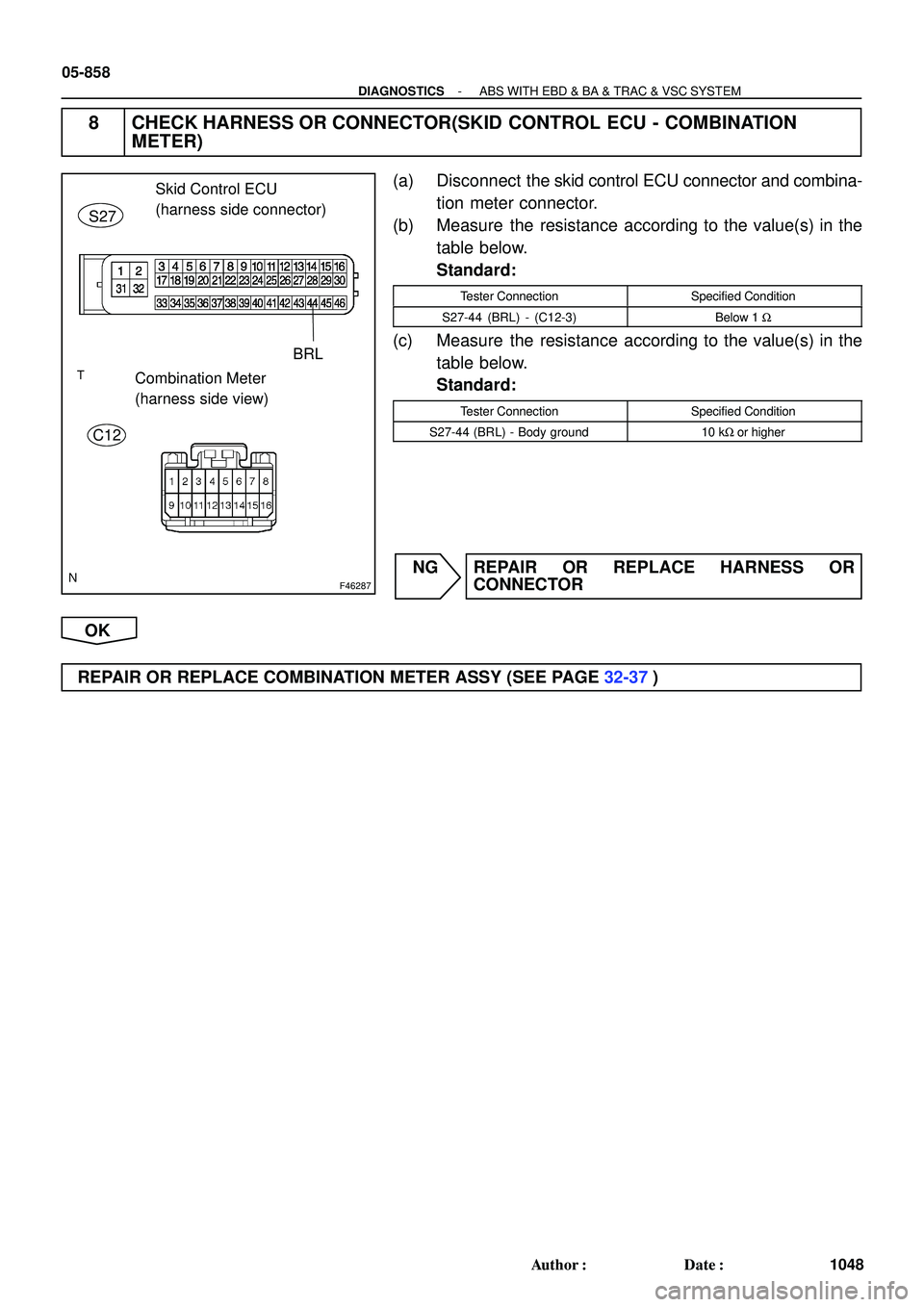
F46287
Skid Control ECU
(harness side connector)
S27
BRL
C12Combination Meter
(harness side view)
05-858
- DIAGNOSTICSABS WITH EBD & BA & TRAC & VSC SYSTEM
1048 Author�: Date�:
8 CHECK HARNESS OR CONNECTOR(SKID CONTROL ECU - COMBINATION
METER)
(a) Disconnect the skid control ECU connector and combina-
tion meter connector.
(b) Measure the resistance according to the value(s) in the
table below.
Standard:
Tester ConnectionSpecified Condition
S27-44 (BRL) - (C12-3)Below 1 W
(c) Measure the resistance according to the value(s) in the
table below.
Standard:
Tester ConnectionSpecified Condition
S27-44 (BRL) - Body ground10 kW or higher
NG REPAIR OR REPLACE HARNESS OR
CONNECTOR
OK
REPAIR OR REPLACE COMBINATION METER ASSY (SEE PAGE 32-37)
Page 750 of 2572
F46304
Combination Meter
Passenger Side J/BABS C11
Instrument Panel J/BSkid Control ECU with Actuator
I15
Ignition SW
F7
FL BlockC11 IF2
IL1 IC4 S27
S27 S27 4E
4H 4JJ6
J/C
IC4
IC1 1A
1C 1D
1G
1C 1C ECU-IG
IGN
AM1IG1 4M
IG2AM1
AM2WA
IG1
GND1
EA EB ALT
AM2
J4
J/C FL MAIN
Battery1
24 6
7 9
10 13
1729
4
446
4
62
10
32 12
12
1 E P W SB R-L
P
ESB
GRB-R
G
GR
W
Y
L-Y WB
W-B Y
W
AW-B 167 10
1
6 05-844
- DIAGNOSTICSABS WITH EBD & BA & TRAC & VSC SYSTEM
1034 Author�: Date�:
ABS WARNING LIGHT CIRCUIT (DOES NOT LIGHT UP)
WIRING DIAGRAM
05F1T-06
Page 751 of 2572
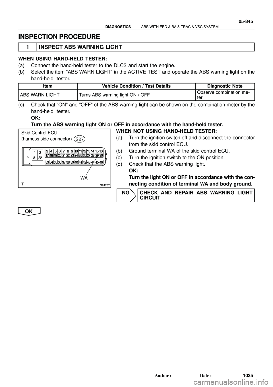
G24767
Skid Control ECU
(harness side connector)
S27
WA
- DIAGNOSTICSABS WITH EBD & BA & TRAC & VSC SYSTEM
05-845
1035 Author�: Date�:
INSPECTION PROCEDURE
1 INSPECT ABS WARNING LIGHT
WHEN USING HAND-HELD TESTER:
(a) Connect the hand-held tester to the DLC3 and start the engine.
(b) Select the item ºABS WARN LIGHTº in the ACTIVE TEST and operate the ABS warning light on the
hand-held tester.
ItemVehicle Condition / Test DetailsDiagnostic Note
ABS WARN LIGHTTurns ABS warning light ON / OFFObserve combination me-
ter
(c) Check that ºONº and ºOFFº of the ABS warning light can be shown on the combination meter by the
hand-held tester.
OK:
Turn the ABS warning light ON or OFF in accordance with the hand-held tester.
WHEN NOT USING HAND-HELD TESTER:
(a) Turn the ignition switch off and disconnect the connector
from the skid control ECU.
(b) Ground terminal WA of the skid control ECU.
(c) Turn the ignition switch to the ON position.
(d) Check that the ABS warning light.
OK:
Turn the light ON or OFF in accordance with the con-
necting condition of terminal WA and body ground.
NG CHECK AND REPAIR ABS WARNING LIGHT
CIRCUIT
OK
Page 752 of 2572
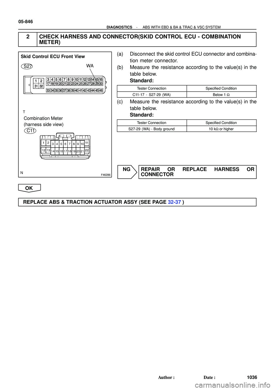
F46286
Skid Control ECU Front View
S27WA
Combination Meter
(harness side view)
C11
05-846
- DIAGNOSTICSABS WITH EBD & BA & TRAC & VSC SYSTEM
1036 Author�: Date�:
2 CHECK HARNESS AND CONNECTOR(SKID CONTROL ECU - COMBINATION
METER)
(a) Disconnect the skid control ECU connector and combina-
tion meter connector.
(b) Measure the resistance according to the value(s) in the
table below.
Standard:
Tester ConnectionSpecified Condition
C11-17 - S27-29 (WA)Below 1 W
(c) Measure the resistance according to the value(s) in the
table below.
Standard:
Tester ConnectionSpecified Condition
S27-29 (WA) - Body ground10 kW or higher
NG REPAIR OR REPLACE HARNESS OR
CONNECTOR
OK
REPLACE ABS & TRACTION ACTUATOR ASSY (SEE PAGE 32-37)
Page 770 of 2572

BR3583
BR3582F00010
RotorSpeed Sensor
Magnet
To ECU
+V
-VHigh Speed
Low Speed
CoilNS
05-788
- DIAGNOSTICSABS WITH EBD & BA & TRAC & VSC SYSTEM
978 Author�: Date�:
DTC C0200/31 RIGHT FRONT SPEED SENSOR
DTC C0205/32 LEFT FRONT SPEED SENSOR
DTC C1235/35 FOREIGN MATTER IS ATTACHED ON TIP OF
RIGHT FRONT SENSOR
DTC C1236/36 FOREIGN MATTER IS ATTACHED ON TIP OF
LEFT FRONT SENSOR
CIRCUIT DESCRIPTION
The speed sensor detects wheel speed and sends the ap-
propriate signals to the ECU. These signals are used to control
the ABS control system. The front and rear rotors have 48
serrations each.
When the rotors rotate, the magnetic field emitted by the perma-
nent magnet in the speed sensor generates AC voltage. Since
the frequency of this AC voltage changes in direct proportion to
the speed of the rotor, the frequency is used by the ECU to de-
tect the speed of each wheel.
DTC No.DTC Detecting ConditionTrouble Area
C0200/31
C0205/32
(1) All the following conditions continues for at least 1 se-
cond.
�Vehicle speed is more than 6 mph (10 km/h).
�Open or short in vehicle speed sensor signal circuit of
faulty wheel continues for 1 second or more.
(2) Momentary interruption of the sensor signal of faulty
wheel has occurred 7 times or more.
(3) Sensor signal circuit is open for 0.5 seconds.
�Right front and left front speed sensor
�Each speed sensor circuit
�Sensor rotor
�Sensor installation
C1235/35
C1236/36All the following conditions for at least 5 seconds.
�Vehicle speed is more than 12 mph (20 km/h).
�Vehicle speed sensor signal receives.�Right front and left front speed sensor
�Each speed sensor
�Sensor installation
HINT:
�DTC C0200/31 and C1235/35 are for the right front speed sensor.
�DTC C0205/32 and C1236/36 are for the left front speed sensor.
05F1P-08
Page 771 of 2572

F40566
Skid Control ECU with Actuator
2
1
1817
FL+
FL- A4
ABS Speed Sensor
Front LH
43
FR+
FR- A5
ABS Speed Sensor
Front RHS27 R-Y
LG
O
P 2
1S27
S27
S27
- DIAGNOSTICSABS WITH EBD & BA & TRAC & VSC SYSTEM
05-789
979 Author�: Date�:
WIRING DIAGRAM
INSPECTION PROCEDURE
HINT:
Start the inspection from step 1 when using the hand-held tester and start from step 3 when not using the
hand-held tester.
1 READ VALUE OF HAND-HELD TESTER(FRONT SPEED SENSOR)
(a) Connect the hand-held tester to the DLC3.
(b) Start the engine.
(c) Select the DATA LIST mode on the hand-held tester.
(d) Check that there is no difference between the speed value output from the speed sensor displayed
on the hand-held tester and the speed value displayed on the speedometer when driving the vehicle.
ItemMeasurement Item /
Range (Display)Normal Condition
WHEEL SPD FR
Wheel speed sensor (FR) reading /
min.: 0 km/h (0 MPH, max.: 326 km/h
(202 MPH)
Actual wheel speed
WHEEL SPD FL
Wheel speed sensor (FL) reading /
min.: 0 km/h (0 MPH, max.: 326 km/h
(202 MPH)
Actual wheel speed
OK:
There is almost no difference from the displayed speed value.
HINT:
There is tolerance of + 10 % in the speedometer indication.
NG Go to step 3
OK
Page 772 of 2572
W04200
Normal Signal Waveform
1 V / Division2 m/s / DivisionGND
05-790
- DIAGNOSTICSABS WITH EBD & BA & TRAC & VSC SYSTEM
980 Author�: Date�:
2 INSPECT SPEED SENSOR AND SENSOR ROTOR SERRATIONS
INSPECTION USING OSCILLOSCOPE
(a) Connect the oscilloscope to terminal FR+ - FR- or FL+
- FL- of the skid control ECU.
(b) Drive the vehicle at about 19 mph (30 km/h), and check
the signal waveform.
OK:
A waveform as shown in a figure should be output.
HINT:
�As the vehicle speed (wheel revolution speed) increases,
a cycle of the waveform narrows and the fluctuation in the
output voltage becomes greater.
�When noise is identified in the waveform on the oscillo-
scope, error signals are generated due to the speed sen-
sor rotor's scratches, looseness or foreign matter at-
tached to it.
NG Go to step 6
OK
REPLACE ABS & TRACTION ACTUATOR ASSY (SEE PAGE 32-37)
Page 773 of 2572
C93876
21
A4 A5
Front Speed Sensor
- DIAGNOSTICSABS WITH EBD & BA & TRAC & VSC SYSTEM
05-791
981 Author�: Date�:
3 INSPECT FRONT SPEED SENSOR
(a) Make sure that there is no looseness at the connectors'
locking part and connecting part of connector.
(b) Disconnect the speed sensor connector.
(c) Measure the resistance according to the value(s) in the
table below.
Standard:
LH:
Tester ConnectionSpecified Condition
A4-1 (FL-) - A4-2 (FL+)0.6 to 2.5 kW
RH:
Tester ConnectionSpecified Condition
A5-1 (FR-) - A5-2 (FR+)0.6 to 2.5 kW
(d) Measure the resistance according to the value(s) in the
table below.
Standard:
LH:
Tester ConnectionSpecified Condition
A4-1 (FL-) - Body ground10 kW or higher
A4-2 (FL+) - Body ground10 kW or higher
RH:
Tester ConnectionSpecified Condition
A5-1 (FR-) - Body ground10 kW or higher
A5-2 (FR+) - Body ground10 kW or higher
NOTICE:
Check the speed sensor signal after replacement
(see page 05-765).
NG REPLACE FRONT SPEED SENSOR
(SEE PAGE 32-40)
OK