Page 1069 of 2572
H41715H44130H44536
Occupant
Classification ECU
FAirbag
Sensor
Assy
Center A
FSR-
FSR+ EDCB
A18
FSR-FSR+
A18
w/ Side and Curtain
Shield Airbagw/o Side and Curtain
Shield Airbag
05-1496
- DIAGNOSTICSSUPPLEMENTAL RESTRAINT SYSTEM
1686 Author�: Date�:
2005 HIGHLANDER REPAIR MANUAL (RM1144U)
3 PREPARE FOR INSPECTION
CAUTION:
Be sure to perform the following procedures before troubleshooting to avoid unexpected airbag de-
ployment.
(a) Turn the ignition switch to the LOCK position.
(b) Disconnect the negative (-) terminal cable from the battery, and wait for at least 90 seconds.
(c) Disconnect the connectors from the airbag sensor assy center.
(d) Disconnect the connectors from the horn button assy.
(e) Disconnect the connectors from the front passenger airbag assy.
(f) Disconnect the connector from the front seat airbag assy LH
(g) Disconnect the connector from the front seat airbag assy RH.
(h) Disconnect the connector from the curtain shield airbag assy LH.
(i) Disconnect the connector from the curtain shield airbag assy RH
(j) Disconnect the connector from the front seat outer belt assy LH.
(k) Disconnect the connector from the front seat outer belt assy RH.
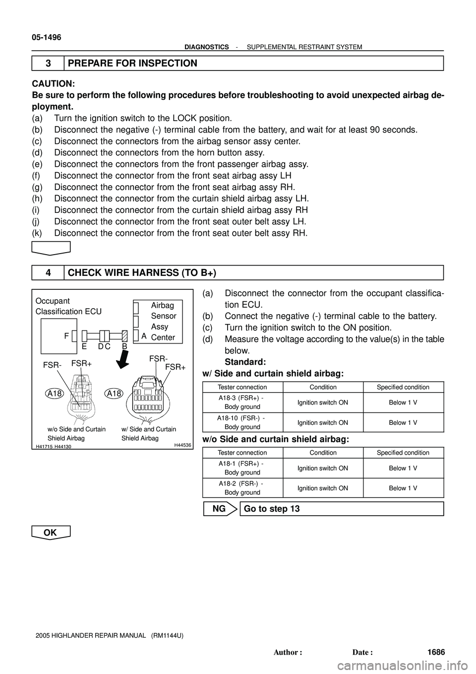
4 CHECK WIRE HARNESS (TO B+)
(a) Disconnect the connector from the occupant classifica-
tion ECU.
(b) Connect the negative (-) terminal cable to the battery.
(c) Turn the ignition switch to the ON position.
(d) Measure the voltage according to the value(s) in the table
below.
Standard:
w/ Side and curtain shield airbag:
Tester connectionConditionSpecified condition
A18-3 (FSR+) -
Body groundIgnition switch ONBelow 1 V
A18-10 (FSR-) -
Body groundIgnition switch ONBelow 1 V
w/o Side and curtain shield airbag:
Tester connectionConditionSpecified condition
A18-1 (FSR+) -
Body groundIgnition switch ONBelow 1 V
A18-2 (FSR-) -
Body groundIgnition switch ONBelow 1 V
NG Go to step 13
OK
Page 1070 of 2572
H41715H44130 H44536H43694H44681
Occupant
Classification ECUAirbag
Sensor
Assy
Center
FSR+ F
CBA
ED
FSR-
FSR-FSR+
Service Wire
O6
A18 A18
(*1) (*2) FSR-
FSR+
*1: w/ Side and Curtain Shield Airbag
*2: w/o Side and Curtain Shield Airbag
H41715H44130H44536
Occupant
Classification ECU
FAirbag
Sensor
Assy
Center A
FSR-
FSR+ EDCB
A18
FSR-FSR+
A18
w/ Side and Curtain
Shield Airbagw/o Side and Curtain
Shield Airbag
- DIAGNOSTICSSUPPLEMENTAL RESTRAINT SYSTEM
05-1497
1687 Author�: Date�:
2005 HIGHLANDER REPAIR MANUAL (RM1144U)
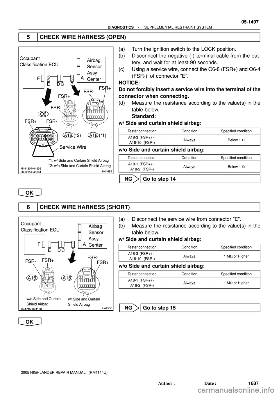
5 CHECK WIRE HARNESS (OPEN)
(a) Turn the ignition switch to the LOCK position.
(b) Disconnect the negative (-) terminal cable from the bat-
tery, and wait for at least 90 seconds.
(c) Using a service wire, connect the O6-8 (FSR+) and O6-4
(FSR-) of connector ºEº.
NOTICE:
Do not forcibly insert a service wire into the terminal of the
connector when connecting.
(d) Measure the resistance according to the value(s) in the
table below.
Standard:
w/ Side and curtain shield airbag:
Tester connectionConditionSpecified condition
A18-3 (FSR+) -
A18-10 (FSR-)AlwaysBelow 1 W
w/o Side and curtain shield airbag:
Tester connectionConditionSpecified condition
A18-1 (FSR+) -
A18-2 (FSR-)AlwaysBelow 1 W
NG Go to step 14
OK
6 CHECK WIRE HARNESS (SHORT)
(a) Disconnect the service wire from connector ºEº.
(b) Measure the resistance according to the value(s) in the
table below.
w/ Side and curtain shield airbag:
Tester connectionConditionSpecified condition
A18-3 (FSR+) -
A18-10 (FSR-)Always1 MW or Higher
w/o Side and curtain shield airbag:
Tester connectionConditionSpecified condition
A18-1 (FSR+) -
A18-2 (FSR-)Always1 MW or Higher
NG Go to step 15
OK
Page 1071 of 2572
H41715H44130H44536
Occupant
Classification ECU
FAirbag
Sensor
Assy
Center A
FSR-
FSR+ EDCB
A18
FSR-FSR+
A18
w/ Side and Curtain
Shield Airbagw/o Side and Curtain
Shield Airbag
05-1498
- DIAGNOSTICSSUPPLEMENTAL RESTRAINT SYSTEM
1688 Author�: Date�:
2005 HIGHLANDER REPAIR MANUAL (RM1144U)
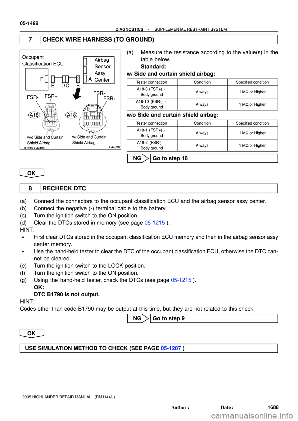
7 CHECK WIRE HARNESS (TO GROUND)
(a) Measure the resistance according to the value(s) in the
table below.
Standard:
w/ Side and curtain shield airbag:
Tester connectionConditionSpecified condition
A18-3 (FSR+) -
Body groundAlways1 MW or Higher
A18-10 (FSR-) -
Body groundAlways1 MW or Higher
w/o Side and curtain shield airbag:
Tester connectionConditionSpecified condition
A18-1 (FSR+) -
Body groundAlways1 MW or Higher
A18-2 (FSR-) -
Body groundAlways1 MW or Higher
NG Go to step 16
OK
8 RECHECK DTC
(a) Connect the connectors to the occupant classification ECU and the airbag sensor assy center.
(b) Connect the negative (-) terminal cable to the battery.
(c) Turn the ignition switch to the ON position.
(d) Clear the DTCs stored in memory (see page 05-1215).
HINT:
�First clear DTCs stored in the occupant classification ECU memory and then in the airbag sensor assy
center memory.
�Use the hand-held tester to clear the DTC of the occupant classification ECU, otherwise the DTC can-
not be cleared.
(e) Turn the ignition switch to the LOCK position.
(f) Turn the ignition switch to the ON position.
(g) Using the hand-held tester, check the DTCs (see page 05-1215).
OK:
DTC B1790 is not output.
HINT:
Codes other than code B1790 may be output at this time, but they are not related to this check.
NG Go to step 9
OK
USE SIMULATION METHOD TO CHECK (SEE PAGE 05-1207)
Page 1072 of 2572
- DIAGNOSTICSSUPPLEMENTAL RESTRAINT SYSTEM
05-1499
1689 Author�: Date�:
2005 HIGHLANDER REPAIR MANUAL (RM1144U)
9 REPLACE OCCUPANT CLASSIFICATION ECU
(a) Turn the ignition switch to the LOCK position.
(b) Disconnect the negative (-) terminal cable from the battery, and wait for at least 90 seconds.
(c) Replace the occupant classification ECU (see page 60-64).
HINT:
Perform the inspection using parts from a normal vehicle when possible.
10 PERFORM ZERO POINT CALIBRATION
(a) Using the hand-held tester, perform ºZero point calibrationº (see page 05-1203).
OK:
The ºCOMPLETEDº is displayed.
11 PERFORM SENSITIVITY CHECK
(a) Using the hand-held tester, perform ºSensitivity checkº (see page 05-1203).
Standard value: 27 to 33 kg (59.52 to 72.75 lb)
12 RECHECK DTC
(a) Connect the connector to the occupant classification ECU.
(b) Connect the negative (-) terminal cable to the battery.
(c) Turn the ignition switch to the ON position.
(d) Clear the DTCs stored in memory (see page 05-1215).
HINT:
�First clear DTCs stored in the occupant classification ECU memory and then in the airbag sensor assy
center memory.
�Use the hand-held tester to clear the DTC of the occupant classification ECU, otherwise the DTC can-
not be cleared.
(e) Turn the ignition switch to the LOCK position.
(f) Turn the ignition switch to the ON position.
(g) Using the hand-held tester, check the DTCs (see page 05-1215).
OK:
DTC B1790 is not output.
HINT:
Codes other than code B1790 may be output at this time, but they are not related to this check.
NG REPLACE AIR BAG SENSOR ASSY CENTER
(SEE PAGE 60-53)
OK
END
Page 1073 of 2572
H03354H43116H03354H43116H43129
Occupant
Classification
ECUFront Seat
Wire RHFloor Wire
Airbag
Sensor
Assy
Center A
B C D E F
FSR-
FSR+
BL1
H03354H43116 H43129H44538
Occupant
Classification
ECUFront Seat
Wire RHFloor Wire
Airbag
Sensor
Assy
Center A
B C D E F
FSR-
FSR+
FSR+
FSR-
O6BL1
Service Wire
05-1500
- DIAGNOSTICSSUPPLEMENTAL RESTRAINT SYSTEM
1690 Author�: Date�:
2005 HIGHLANDER REPAIR MANUAL (RM1144U)
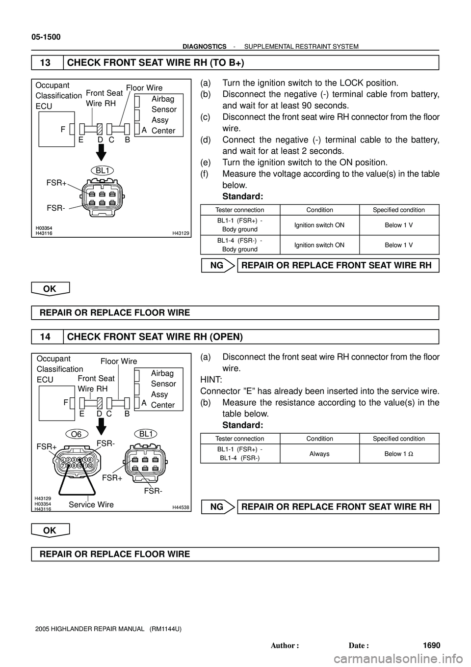
13 CHECK FRONT SEAT WIRE RH (TO B+)
(a) Turn the ignition switch to the LOCK position.
(b) Disconnect the negative (-) terminal cable from battery,
and wait for at least 90 seconds.
(c) Disconnect the front seat wire RH connector from the floor
wire.
(d) Connect the negative (-) terminal cable to the battery,
and wait for at least 2 seconds.
(e) Turn the ignition switch to the ON position.
(f) Measure the voltage according to the value(s) in the table
below.
Standard:
Tester connectionConditionSpecified condition
BL1-1 (FSR+) -
Body groundIgnition switch ONBelow 1 V
BL1-4 (FSR-) -
Body groundIgnition switch ONBelow 1 V
NG REPAIR OR REPLACE FRONT SEAT WIRE RH
OK
REPAIR OR REPLACE FLOOR WIRE
14 CHECK FRONT SEAT WIRE RH (OPEN)
(a) Disconnect the front seat wire RH connector from the floor
wire.
HINT:
Connector ºEº has already been inserted into the service wire.
(b) Measure the resistance according to the value(s) in the
table below.
Standard:
Tester connectionConditionSpecified condition
BL1-1 (FSR+) -
BL1-4 (FSR-)AlwaysBelow 1 W
NG REPAIR OR REPLACE FRONT SEAT WIRE RH
OK
REPAIR OR REPLACE FLOOR WIRE
Page 1074 of 2572
H03354H43116H03354H43116H43129
Occupant
Classification
ECUFront Seat
Wire RHFloor Wire
Airbag
Sensor
Assy
Center A
B C D E F
FSR-
FSR+
BL1
H03354H43116H03354H43116H43129
Occupant
Classification
ECUFront Seat
Wire RHFloor Wire
Airbag
Sensor
Assy
Center A
B C D E F
FSR-
FSR+
BL1
- DIAGNOSTICSSUPPLEMENTAL RESTRAINT SYSTEM
05-1501
1691 Author�: Date�:
2005 HIGHLANDER REPAIR MANUAL (RM1144U)
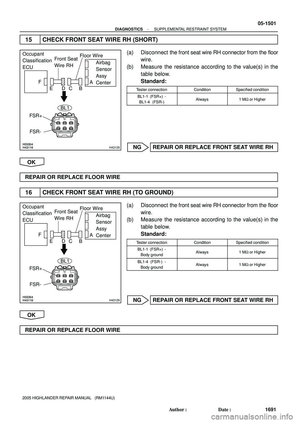
15 CHECK FRONT SEAT WIRE RH (SHORT)
(a) Disconnect the front seat wire RH connector from the floor
wire.
(b) Measure the resistance according to the value(s) in the
table below.
Standard:
Tester connectionConditionSpecified condition
BL1-1 (FSR+) -
BL1-4 (FSR-)Always1 MW or Higher
NG REPAIR OR REPLACE FRONT SEAT WIRE RH
OK
REPAIR OR REPLACE FLOOR WIRE
16 CHECK FRONT SEAT WIRE RH (TO GROUND)
(a) Disconnect the front seat wire RH connector from the floor
wire.
(b) Measure the resistance according to the value(s) in the
table below.
Standard:
Tester connectionConditionSpecified condition
BL1-1 (FSR+) -
Body groundAlways1 MW or Higher
BL1-4 (FSR-) -
Body groundAlways1 MW or Higher
NG REPAIR OR REPLACE FRONT SEAT WIRE RH
OK
REPAIR OR REPLACE FLOOR WIRE
Page 1075 of 2572
05-1502
- DIAGNOSTICSSUPPLEMENTAL RESTRAINT SYSTEM
1692 Author�: Date�:
2005 HIGHLANDER REPAIR MANUAL (RM1144U)
DTC B1793 OCCUPANT CLASSIFICATION SENSOR
POWER SUPPLY CIRCUIT MALFUNCTION
CIRCUIT DESCRIPTION
The occupant classification sensor power supply circuit consists of the occupant classification ECU and the
occupant classification sensors.
DTC B1793 is recorded when a malfunction is detected in the occupant classification sensor power supply
circuit.
DTC No.DTC Detecting ConditionTrouble Area
B1793
�When the occupant classification ECU receives a line
short signal, an open signal, short to ground signal or B+
short signal in the occupant classification sensor power
supply circuit for 2 seconds.
�Open circuit in occupant classification sensors wire har-
ness
�Occupant classification ECU malfunction
�Seat adjuster frame assy (Occupant classification sensors)
�Front seat wire RH
�Occupant classification ECU
HINT:
�When DTC B1150/23 is detected as a result of troubleshooting for the supplemental restraint system,
perform troubleshooting for DTC B1793 of the occupant classification sensor.
�Use the hand-held tester to check the DTC of the occupant classification ECU, otherwise the DTC
cannot be read.
05IWZ-02
Page 1076 of 2572
H43061
O11
Occupant Classification
Sensor Rear RHOccupant Classification ECU
1V
O76
SVC4
SVC2
SVC3
SVC1 O9
Occupant Classification
Sensor Front RH
1W
O712
O10
Occupant Classification
Sensor Rear LH
1O75
O8
Occupant Classification
Sensor Front LH
1R
O711 GR SVC4
SVC2
SVC3
SVC1
- DIAGNOSTICSSUPPLEMENTAL RESTRAINT SYSTEM
05-1503
1693 Author�: Date�:
2005 HIGHLANDER REPAIR MANUAL (RM1144U)
WIRING DIAGRAM