Page 219 of 2572
'05 HIGHLANDER_U (L/O 0409)
99
2005 HIGHLANDER from Nov. '04 Prod. (OM48570U)
CAUTION
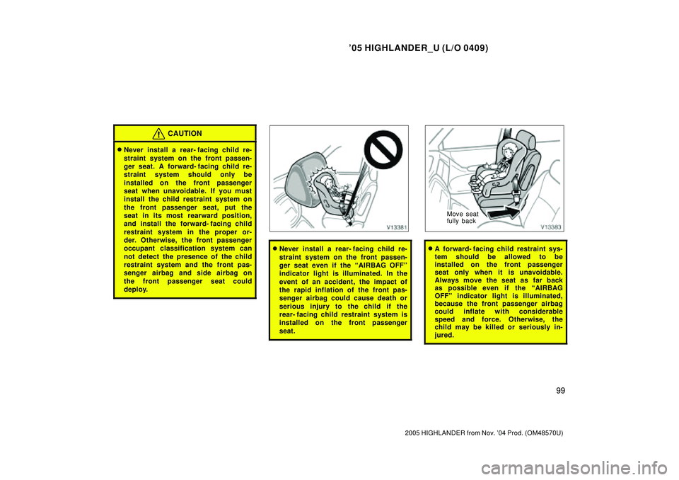
�Never install a rear- facing child re-
straint system on the front passen-
ger seat. A forward- facing child re-
straint system should only be
installed on the front passenger
seat when unavoidable. If you must
install the child restraint system on
the front passenger seat, put the
seat in its most rearward position,
and install the forward- facing child
restraint system in the proper or-
der. Otherwise, the front passenger
occupant classification system can
not detect the presence of the child
restraint system and the front pas-
senger airbag and side airbag on
the front passenger seat could
deploy.
�Never install a rear- facing child re-
straint system on the front passen-
ger seat even if the AIRBAG OFFº
indicator light is illuminated. In the
event of an accident, the impact of
the rapid inflation of the front pas-
senger airbag could cause death or
serious injury to the child if the
rear- facing child restraint system is
installed on the front passenger
seat.
Move seat
fully back
�A forward- facing child restraint sys-
tem should be allowed to be
installed on the front passenger
seat only when it is unavoidable.
Always move the seat as far back
as possible even if the AIRBAG
OFFº indicator light is illuminated,
because the front passenger airbag
could inflate with considerable
speed and force. Otherwise, the
child may be killed or seriously in-
jured.
Page 221 of 2572
'05 HIGHLANDER_U (L/O 0409)
101
2005 HIGHLANDER from Nov. '04 Prod. (OM48570U)
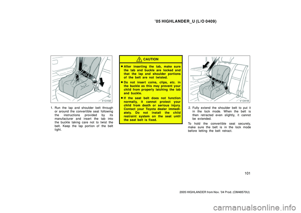
1. Run the lap and shoulder belt through
or around the convertible seat following
the instructions provided by its
manufacturer and insert the tab into
the buckle taking care not to twist the
belt. Keep the lap portion of the belt
tight.
CAUTION
�After inserting the tab, make sure
the tab and buckle are locked and
that the lap and shoulder portions
of the belt are not twisted.
�Do not insert coins, clips, etc. in
the buckle as this may prevent your
child from properly latching the tab
and buckle.
�If the seat belt does not function
normally, it cannot protect your
child from death or serious injury.
Contact your Toyota dealer immedi-
ately. Do not install the child
restraint system on the seat until
the seat belt is fixed.
2. Fully extend the shoulder belt to put it
in the lock mode. When the belt is
then retracted even slightly, it cannot
be extended.
To hold the convertible seat securely,
make sure the belt is in the lock mode
before letting the belt retract.
Page 223 of 2572
'05 HIGHLANDER_U (L/O 0409)
103
2005 HIGHLANDER from Nov. '04 Prod. (OM48570U)
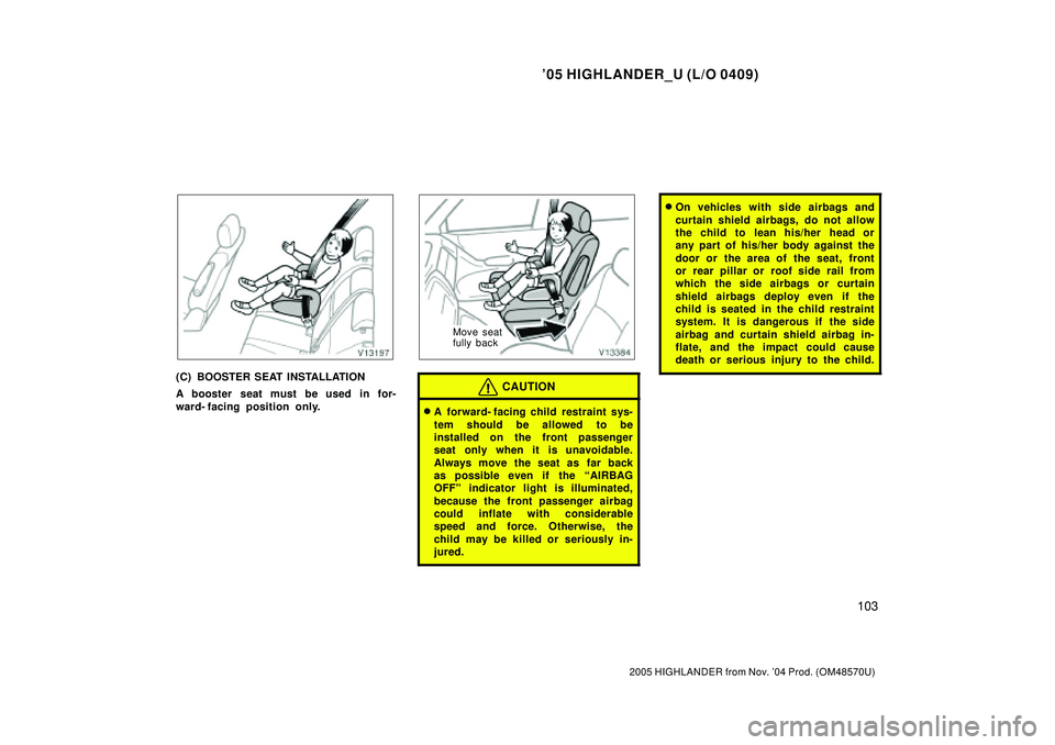
(C) BOOSTER SEAT INSTALLATION
A booster seat must be used in for-
ward- facing position only.
Move seat
fully back
CAUTION
�A forward- facing child restraint sys-
tem should be allowed to be
installed on the front passenger
seat only when it is unavoidable.
Always move the seat as far back
as possible even if the AIRBAG
OFFº indicator light is illuminated,
because the front passenger airbag
could inflate with considerable
speed and force. Otherwise, the
child may be killed or seriously in-
jured.
�On vehicles with side airbags and
curtain shield airbags, do not allow
the child to lean his/her head or
any part of his/her body against the
door or the area of the seat, front
or rear pillar or roof side rail from
which the side airbags or curtain
shield airbags deploy even if the
child is seated in the child restraint
system. It is dangerous if the side
airbag and curtain shield airbag in-
flate, and the impact could cause
death or serious injury to the child.
Page 229 of 2572
'05 HIGHLANDER_U (L/O 0409)
109
2005 HIGHLANDER from Nov. '04 Prod. (OM48570U)
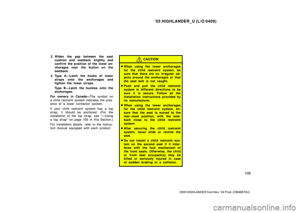
2. Widen the gap between the seat
cushion and seatback slightly and
confirm the position of the lower an-
chorages near the button on the
seatback.
3. Type AÐLatch the hooks of lower
straps onto the anchorages and
tighten the lower straps.
Type BÐLatch the buckles onto the
anchorages.
For owners in CanadaÐThe symbol on
a child restraint system indicates the pres-
ence of a lower connector system.
If your child restraint system has a top
strap, it should be anchored. (For the
installation of the top strap, see ÐUsing
a top strapº on page 105 in this Section.)
For installation details, refer to the instruc-
tion manual equipped with each product.CAUTION
�When using the lower anchorages
for the child restraint system, be
sure that there are no irregular ob-
jects around the anchorages or that
the seat belt is not caught.
�Push and pull the child restraint
system in different directions to be
sure it is secure. Follow all the
installation instructions provided by
its manufacturer.
�When using the lower anchorages
for the child restraint system, en-
sure that the seat is moved to the
rear- most position, with the seat-
back close to the child restraint
system.
�After securing the child restraint
system, never slide or recline the
seat.
�Do not install a child restraint sys-
tem on the second seat if it inter-
feres with the lock mechanism of
the front seats. Otherwise, the child
or front seat occupant(s) may be
killed or seriously injured in case
of sudden braking or a collision.
Page 238 of 2572
'05 HIGHLANDER_U (L/O 0409)
11 4
2005 HIGHLANDER from Nov. '04 Prod. (OM48570U)
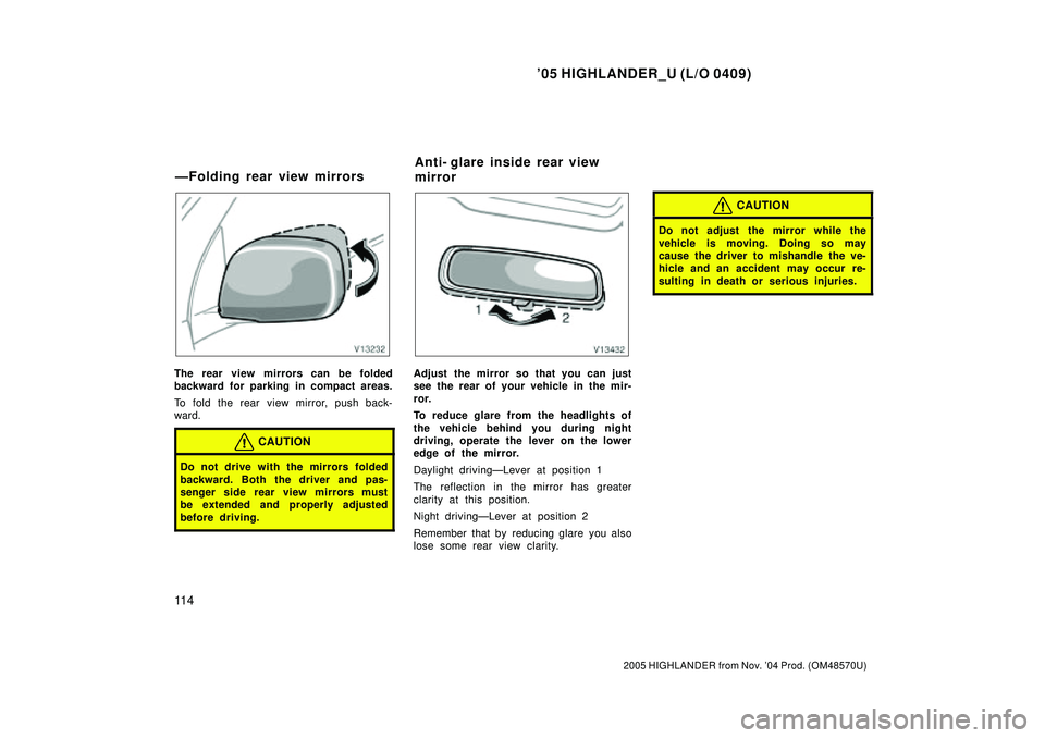
The rear view mirrors can be folded
backward for parking in compact areas.
To fold the rear view mirror, push back-
ward.
CAUTION
Do not drive with the mirrors folded
backward. Both the driver and pas-
senger side rear view mirrors must
be extended and properly adjusted
before driving.
Adjust the mirror so that you can just
see the rear of your vehicle in the mir-
ror.
To reduce glare from the headlights of
the vehicle behind you during night
driving, operate the lever on the lower
edge of the mirror.
Daylight drivingÐLever at position 1
The reflection in the mirror has greater
clarity at this position.
Night drivingÐLever at position 2
Remember that by reducing glare you also
lose some rear view clarity.
CAUTION
Do not adjust the mirror while the
vehicle is moving. Doing so may
cause the driver to mishandle the ve-
hicle and an accident may occur re-
sulting in death or serious injuries.
ÐFolding rear view mirrorsAnti- glare inside rear view
mirror
Page 239 of 2572
'05 HIGHLANDER_U (L/O 0409)
11 5
2005 HIGHLANDER from Nov. '04 Prod. (OM48570U)
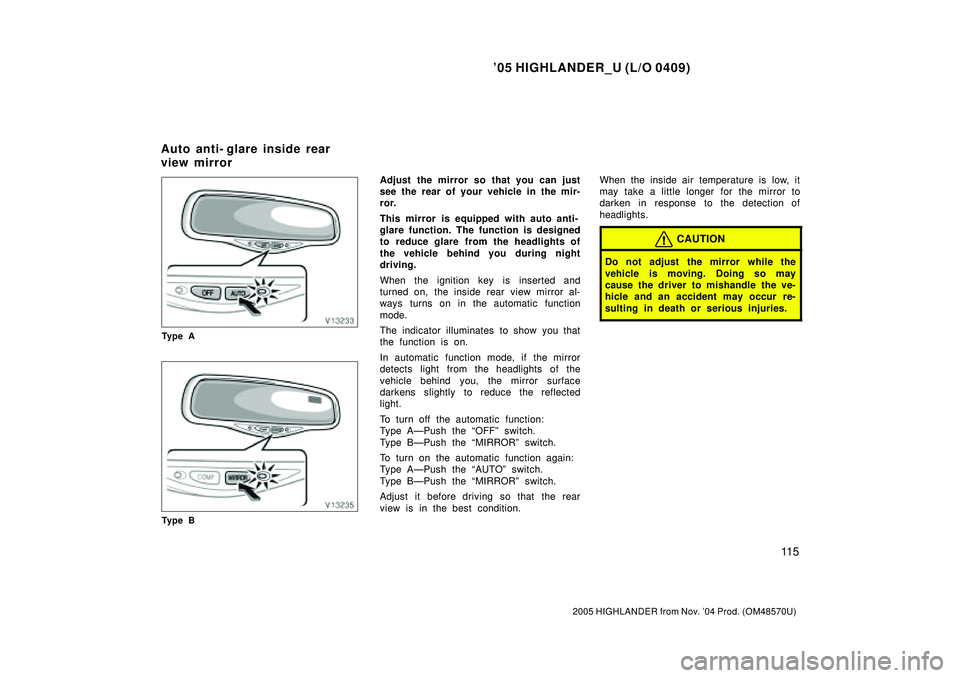
Ty p e A
Ty p e B
Adjust the mirror so that you can just
see the rear of your vehicle in the mir-
ror.
This mirror is equipped with auto anti-
glare function. The function is designed
to reduce glare from the headlights of
the vehicle behind you during night
driving.
When the ignition key is inserted and
turned on, the inside rear view mirror al-
ways turns on in the automatic function
mode.
The indicator illuminates to show you that
the function is on.
In automatic function mode, if the mirror
detects light from the headlights of the
vehicle behind you, the mirror surface
darkens slightly to reduce the reflected
light.
To turn off the automatic function:
Type AÐPush the OFFº switch.
Type BÐPush the MIRRORº switch.
To turn on the automatic function again:
Type AÐPush the AUTOº switch.
Type BÐPush the MIRRORº switch.
Adjust it before driving so that the rear
view is in the best condition.When the inside air temperature is low, it
may take a little longer for the mirror to
darken in response to the detection of
headlights.
CAUTION
Do not adjust the mirror while the
vehicle is moving. Doing so may
cause the driver to mishandle the ve-
hicle and an accident may occur re-
sulting in death or serious injuries.
Auto anti- glare inside rear
view mirror
Page 241 of 2572
'05 HIGHLANDER_U (L/O 0409)
11 7
2005 HIGHLANDER from Nov. '04 Prod. (OM48570U)
CAUTION
Do not extend the plate at the end of
the sun visor when the visor is in the
position 1. It can cover the anti- glare
inside rear view mirror and obstruct
the rear view.
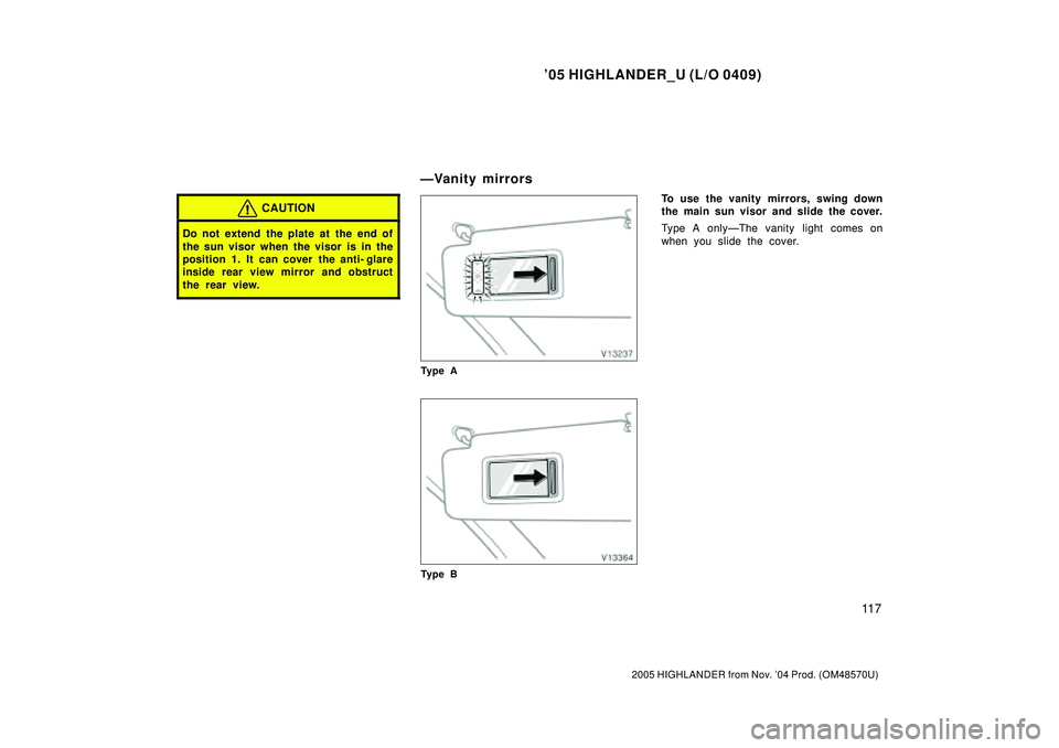
Ty p e A
Ty p e B
To use the vanity mirrors, swing down
the main sun visor and slide the cover.
Type A onlyÐThe vanity light comes on
when you slide the cover.
ÐVanity mirrors
Page 245 of 2572

2005 HIGHLANDER (EWD592U)
76
Engine Control for 3MZ-FE
14 BJ1 I 9
2
18 BJ1 IM1
5IO1 2
E 3E2E1E 16
B
Y
L
NSW
#30 #20 #10
B- R
E 17
STA
B
R- W
516 IO1
RR
V14
B
4
NPGR
R
W- B BR BR
P
12
IM1
V
7. 5A
STARTER
W- B
E147IO1
L- B
THA1E14 E14B- R
4 20 E20A
STOP
1E 1
2 1
2 1
E 29 E 30
5 1 32
B- R B- R
E2G VGPRG ACIS STP
G R- Y BR Y
B- R B- R L- WR B- R
E14I 6
1 2C 2E21 E18 E 19
16 5Y VTA1 VC THW
LG- B
Y R- WW
YV 2S15
M 1
T13
W- B
W- B
W- B
C 8
FAN NO. 1 Relay
CF E 34 E 15 B 19
IM1 13 2
4M 124L 3 IC1
L- W
M-
B- R
1 2
CCVE 27SB L
R- Y
15
IO1
B
EB2 3425
10A
ETCS
W
+BM 6B2
Y
LE 7
B- R L B- R P 1
GR B- RGR
R- W
16 BJ1 B
B- R
B- R
BR
E14 BRBR
B 5
A 5E 28E2
BR BR
BP P
5 EB2
BR BR E 31
4 VTA2
B- R
C 3
2
B
M+
3E2 M+ M- VTA1 VTA2 VC C 17GE0 1
(
*1)
IM1 14
L
BI1 3
BJ117
BR Fr om Power Source System (
See Page 62)
FAN NO. 2 Relay
E 5(
A)
, E 6(
B)
, E 7(
E)
, E 8(
D)
, E 9(
C)
S28(
A)
, S29(
B)
Engine Control Module
Mass Air Flow
Meter
Park/Neutral
Position SW
Stop Light SW
Short Connector
Throttle Control Motor
VSV (
ACIS No. 2)
VSV
(
Canister Closed Valve) VSV (
EVAP) V 4 Engine Coolant Temp.
Sensor E 2
VG E2G THA
+B E2
Throttle Position Sensor