Page 244 of 1897
 H 20.9 mm
(0.823 in.)
7
V RH Line
90 °
V LH Line4V LH LineV Line V RH Line 65
6
V LH LineV Line
V RH Line 6
5
6
H4
O: step No.
7
H4
20.9 mm
(0.823 in.)
20.9 mm
(0.823 i")
I18944
0.4 °
3 m (9.84 ft) H 20.9 mm
(0.823 in.)
7
V RH Line
90 °
V LH Line4V LH LineV Line V RH Line 65
6
V LH LineV Line
V RH Line 6
5
6
H4
O: step No.
7
H4
20.9 mm
(0.823 in.)
20.9 mm
(0.823 in.) 1,342mm (52.8 in.) Low Beam:
High Beam:20.9 mm
(0.823 in.)
20.9 mm
(0.823 in.)
1,342mm (52.8 in.)
1,342mm
(52.8 in.) Hight Bearm
Low Bearm BE-24
- BODY ELECTRICALHEADLIGHT AND TAILLIGHT SYSTEM
1628 Author�: Date�:
2. ADJUST HEADLIGHT AIM ONLY
(a) Place the vehicle in the following conditions.
�The area around the headlight is not deformed.
�The vehicle is parked on a level surface.
�Tire inflation pressure is the specified value.
�A driver is in the driver's seat and the vehicle is in a state ready for driving (with a tank full).
�The vehicle has been bounced several times.
(b) Check the headlight aiming.
(1) Prepare a thick white paper.
(2) Stand the paper perpendicular to the ground at the position 9.84 ft away from the headlights.
(3) Ensure that the center line of the vehicle and the paper face forms a 90-degree angle as shown
in the illustration.
(4) Draw a horizontal line (H line) on the paper, showing where the headlights should strike.
(5) Draw a vertical line (V line) to where the center line of the vehicle is to be.
(6) Draw 2 vertical lines (by connecting the low and high beam center marks) to where the both head-
lights should strike (V RH and V LH lines).
(7) Draw a horizontal line (by connecting the both low beam center marks) to where the headlights
should strike (H RH and H LH lines).
HINT:
The H RH and H LH line is 0.4° below the horizontal line (H line) of the light axis.
(8) Start the engine.
(9) Turn the headlights ON.
(10) Check that the headlights properly strike the position shown in the illustration.
(11) If not, adjust the lights in the vertical direction.
HINT:
As shown in the illustration, adjust each aim of the RH and LH lights.
(c) When adjusting it in the vertical direction:
Using adjusting bolt, adjust the headlight aim to within the specified range.
Page 250 of 1897
BE0HV-04
I12524
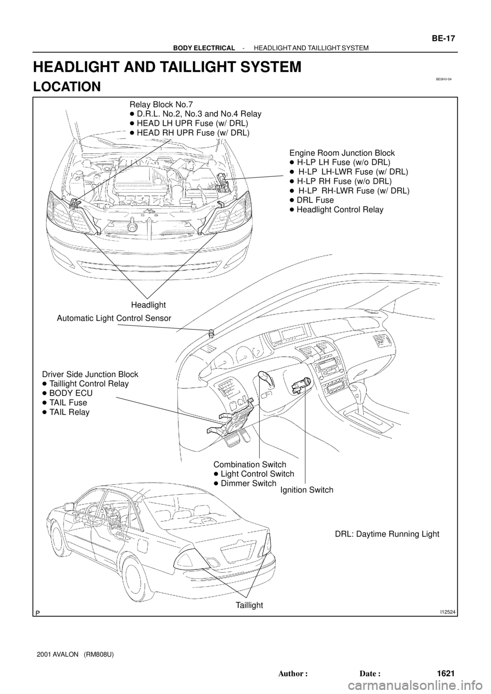
Relay Block No.7
� D.R.L. No.2, No.3 and No.4 Relay
� HEAD LH UPR Fuse (w/ DRL)
� HEAD RH UPR Fuse (w/ DRL)
Engine Room Junction Block
� H-LP LH Fuse (w/o DRL)
� H-LP LH-LWR Fuse (w/ DRL)
� H-LP RH Fuse (w/o DRL)
� H-LP RH-LWR Fuse (w/ DRL)
� DRL Fuse
� Headlight Control Relay
Headlight
Driver Side Junction Block
� Taillight Control Relay
� BODY ECU
� TAIL Fuse
� TAIL Relay
Ignition Switch
Taillight
Combination Switch
� Light Control Switch
� Dimmer Switch
Automatic Light Control Sensor
DRL: Daytime Running Light
- BODY ELECTRICALHEADLIGHT AND TAILLIGHT SYSTEM
BE-17
1621 Author�: Date�:
2001 AVALON (RM808U)
HEADLIGHT AND TAILLIGHT SYSTEM
LOCATION
Page 258 of 1897
 To disable auto door lock:
(1) Enter the vehicle and shut")
BE212-01
BE-88
- BODY ELECTRICALPOWER DOOR LOCK CONTROL SYSTEM
1692 Author�: Date�:
ADJUSTMENT
ENABLING/DISABLING AUTO DOOR LOCK FUNCTION
(a) To disable auto door lock:
(1) Enter the vehicle and shut all doors.
(2) Insert the key into the ignition cylinder and turn it to
the ON position (not ACC).
(3) Open the driver's door and keep it open.
(4) Turn the key to the LOCK position and remove it
from the ignition cylinder.
(5) Insert the key into the ignition cylinder and remove
it. Repeat this operation three more times. (End this
step with the key out of the ignition cylinder.)
(6) Push the ºUNLOCKº button on the driver's door
master switch 5 times within 10 seconds. Wait at
least 10 seconds and shut the driver's door.
(7) Verify auto lock operation has been disabled by
starting the engine, putting the vehicle into a gear
and releasing the brake pedal.
(b) To enable auto door lock:
Follow the same sequence as above, except step 6. In step 6,
push the ºLOCKº button on the driver's door master switch 5
times within 10 seconds. Wait at least 10 seconds and shut the
driver 's door.
Page 274 of 1897
BE1DF-01
I12522
Relay Block No.8Engine Room
Junction Block
Relay Block No.7
Instrument Panel Junction Block
- BODY ELECTRICALPOWER SOURCE
BE-9
1613 Author�: Date�:
2001 AVALON (RM808U)
POWER SOURCE
LOCATION
Page 275 of 1897

I12519
1. MAIN Fuse - 40 A
2. RDI Fuse - 30 A
3. CDS Fuse - 30 A
4. HAZ Fuse - 15 A
5. SRS WRN Fuse - 5 A
6. DCC 1 Fuse - 30 A
7. ALT-S Fuse - 5 A
8. AM2 Fuse - 10 A
9. HORN Fuse - 10 A
10. DOOR NO. 2 Fuse - 15 A
11. A/F Fuse - 25 A
12. IG2 Fuse - 15 A
13. EFI NO. 1 Fuse - 15 A
14. ABS NO. 2 Fuse - 25 A
15. ABS NO. 3 Fuse - 25 A
16. EFI NO. 2 Fuse - 7.5 A
17. ALT Fuse - 120 A
18. ABS Fuse - 60 A
19. DRL Fuse - 7.5 A
20. ABS NO. 4 Fuse - 5 A
21. HTR Fuse - 50 A
22. AM1 Fuse - 40 AEngine Room Junction Block:
1
A
D
G 2
B
E
H 3
C
F
1011
1213141516
98
45
29
28
67
20
27
30
19
2625
2324
23. H-LP LH Fuse - 15 A *2
24. H-LP RH Fuse - 15 A *2
25. H-LP LH LWR Fuse - 15 A *1
26. H-LP RH LWR Fuse - 15 A *1
27. SPARE Fuse - 10 A
28. SPARE Fuse - 15 A
29. SPARE Fuse - 25 A
30. SPARE Fuse - 30 AA. MG/CLT Relay
B. A/F Relay
C. HORN Relay
D. EFI Relay
E. IG2 Relay
F. ST Relay
G. HEAD Relay
H. HTR Relay Relays: Fuses:
*1: w/ Daytime Running Light
*2: w/o Daytime Running Light 1718
21 22
BE-10
- BODY ELECTRICALPOWER SOURCE
1614 Author�: Date�:
2001 AVALON (RM808U)
Page 308 of 1897

COMBINATION METER (Meter, Gauges and Illumination):
SymptomSuspect AreaSee page
Tachometer, Fuel Gauge and Engine Cool")
BE-4
- BODY ELECTRICALTROUBLESHOOTING
1608 Author�: Date�:
2001 AVALON (RM808U)
COMBINATION METER (Meter, Gauges and Illumination):
SymptomSuspect AreaSee page
Tachometer, Fuel Gauge and Engine Coolant Temperature Gauge
do not operate.
1. ECU-B Fuse
2. ECU-IG No. 2 Fuse
3. Meter Circuit Plate
4. Wire Harness
5. Multi Display-
-
BE-43
-
-
Speedometer does not operate.
1. Vehicle Speed Sensor (ABS - ECU)
2. Meter Circuit Plate
3. Wire Harness
4. Multi DisplayBE-53
BE-43
-
-
Tachometer does not operate.
1. EFI - ECU
2. Meter Circuit Plate
3. Wire Harness
4. Multi Display-
BE-43
-
-
Fuel Gauge does not operate or abnormal operation.
1. Fuel Receiver Gauge
2. Fuel Sender Gauge
3. Meter Circuit Plate
4. Wire HarnessBE-53
BE-53
BE-43
-
Engine Coolant Temperature Gauge does not operate or abnormal
operation.
1. Engine Coolant Temperature Receiver Gauge
2. Engine Coolant Temperature Sender Gauge
3. Meter Circuit Plate
4. Wire HarnessBE-53
BE-53
BE-43
-
All illumination lights do not light up.
1. Bulb
2. PANEL Fuse
3. Light Control Rheostat
4. Wire Harness-
-
BE-53
-
Brightness does not change even when rheostat turned.
1. Bulb
2. Rheostat
3. Wire Harness-
-
-
Only one illumination light does not light up.1. Bulb
2. Wire Harness-
-
COMBINATION METER (Warning Lights):
SymptomSuspect AreaSee page
Warning lights do not light up. (Except Discharge, Open Door and
SRS)
1. Bulb
2. GAUGE No. 1 Fuse
3. Meter Circuit Plate
4. Wire Harness-
-
BE-53
-
Low Oil Pressure warning light does not light up.
1. Multi Display
2. Bulb
3. Low Oil Pressure Warning Switch
4. Meter Circuit Plate
5. Wire Harness-
-
BE-53
BE-43
-
Fuel Level warning light does not light up.
1. Multi Display
2. Bulb
3. Fuel Sender Gause
4. Meter Circuit Plate
5. Wire Harness-
-
BE-53
BE-43
-
ABS warning light does not light up.
1. Bulb
2. ABS ECU
3. Wire Harness-
DI-210
-
Page 314 of 1897
BE0I0-04
I12526
Turn Signal Light
Combination Switch
� Turn Signal Switch
Turn Signal Light
Hazard Warning Switch
Flasher Relay
Engine Room Junction Block
� HAZ Fuse
Driver Side Junction Block
� TURN Fuse
BE-28
- BODY ELECTRICALTURN SIGNAL AND HAZARD WARNING SYSTEM
1632 Author�: Date�:
2001 AVALON (RM808U)
TURN SIGNAL AND HAZARD WARNING SYSTEM
LOCATION
Page 324 of 1897
BE1DZ-02
I20800
Driver Side Junction Block
� Door No.1 Fuse
� Body ECU Engine Room Junction Block
� Door No.2 Fuse
Front Door Lock Assembly
Rear Door Lock Assembly
Transmitter
Wireless Door Lock Control Receiver
- BODY ELECTRICALWIRELESS DOOR LOCK CONTROL SYSTEM
BE-89
1693 Author�: Date�:
2001 AVALON (RM808U)
WIRELESS DOOR LOCK CONTROL SYSTEM
LOCATION