Page 1463 of 1897
LU0IB-01
P18778
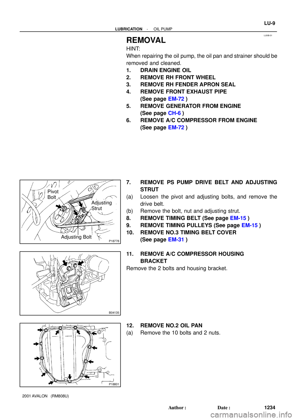
Pivot
Bolt
Adjusting
Strut
Adjusting Bolt
B04135
P18801
- LUBRICATIONOIL PUMP
LU-9
1234 Author�: Date�:
2001 AVALON (RM808U)
REMOVAL
HINT:
When repairing the oil pump, the oil pan and strainer should be
removed and cleaned.
1. DRAIN ENGINE OIL
2. REMOVE RH FRONT WHEEL
3. REMOVE RH FENDER APRON SEAL
4. REMOVE FRONT EXHAUST PIPE
(See page EM-72)
5. REMOVE GENERATOR FROM ENGINE
(See page CH-6)
6. REMOVE A/C COMPRESSOR FROM ENGINE
(See page EM-72)
7. REMOVE PS PUMP DRIVE BELT AND ADJUSTING
STRUT
(a) Loosen the pivot and adjusting bolts, and remove the
drive belt.
(b) Remove the bolt, nut and adjusting strut.
8. REMOVE TIMING BELT (See page EM-15)
9. REMOVE TIMING PULLEYS (See page EM-15)
10. REMOVE NO.3 TIMING BELT COVER
(See page EM-31)
11. REMOVE A/C COMPRESSOR HOUSING
BRACKET
Remove the 2 bolts and housing bracket.
12. REMOVE NO.2 OIL PAN
(a) Remove the 10 bolts and 2 nuts.
Page 1466 of 1897

BODY
INSPECTION
1. TIGHTEN BOLTS AND NUTS ON CHASSIS AND BODY
Tighten the following parts:
�Front s")
MA0676B00995
MA01P-02
B08916
B09029
MA-8
- MAINTENANCEBODY
50 Author�: Date�:
2001 AVALON (RM808U)
BODY
INSPECTION
1. TIGHTEN BOLTS AND NUTS ON CHASSIS AND BODY
Tighten the following parts:
�Front seat mount bolts
Torque: 37 N´m (375 kgf´cm, 27 ft´lbf)
�Front suspension member-to-body mounting bolts
Torque: 181 N´m (1,850 kgf´cm, 134 ft´lbf)
�Rear suspension member-to-body mounting nuts
Torque: 51 N´m (520 kgf´cm, 38 ft´lbf)
2. FINAL INSPECTION
(a) Check the operation of the body parts:
�Hood:
Auxiliary catch operates properly
Hood locks securely when closed
�Front and rear doors:
Door lock operates properly
Doors close properly
�Luggage compartment door:
Door lock operates properly
�Seats:
Seat adjusts easily and locks securely in any posi-
tion
Front seat back locks securely in any position
Folding-down rear seat backs lock securely
(b) Road test:
�Check the engine and chassis for abnormal noises.
�Check that the vehicle dose not wander or pull to
one side.
�Check that the brakes work properly and do not
drag.
�Do setting of the parking brake shoes and drum.
(c) Be sure to deliver a clean car and especially check:
�Steering wheel
�Shift lever knob
�All switch knobs
�Door handles
�Seats
Page 1743 of 1897

H11891
Connector
AB0163
Wire Harness
Diameter
Stripped Wire Harness Section
H11892
L
M
RS-20
- SUPPLEMENTAL RESTRAINT SYSTEMSTEERING WHEEL PAD AND SPIRAL CABLE
1540 Author�: Date�:
2001 AVALON (RM808U)
(a) Remove the steering wheel pad (See page SR-12).
CAUTION:
�When removing the steering wheel pad, work must be
started 90 seconds after the ignition switch is turned
to the ºLOCKº position and the negative (-) terminal
cable is disconnected from the battery.
�When storing the steering wheel pad, keep the upper
surface of the pad facing upward.
(b) Remove the connector on the rear surface of the steering
wheel pad from the bracket.
(c) Using a service-purpose wire harness tie down the steer-
ing wheel pad to the disc wheel.
Wire harness: Stripped wire harness section
1.25 mm
2
or more (0.0019 in2. or more)
CAUTION:
If a wire harness which is too thin or some other thing is
used to tie down the steering wheel pad, it may be snapped
by the shock when the airbag is deployed. This is highly
dangerous. Always use a wire harness for vehicle use
which is at least 1.25 mm
2
(0.0019 in2.).
HINT:
To calculate the square of the stripped wire harness section:
Square = 3.14 x (Diameter)
2 divided by 4
(1) Install the 2 bolts with washers in the 2 bolt holes in
the steering wheel pad.
Bolt:
L: 35. mm (1.387 in.)
M: 6.0 mm (0.236 in.)
Pitch: 1.0 mm (0.039 in.)
NOTICE:
�Tighten the bolts by hand until the bolts become diffi-
cult to turn.
�Do not tighten the bolts too much.
Page 1744 of 1897

(2) Using 3 wire harness, wind the")
H11893
2 Times or more
H11894
AB0158
SSTBattery
- SUPPLEMENTAL RESTRAINT SYSTEMSTEERING WHEEL PAD AND SPIRAL CABLE
RS-21
1541 Author�: Date�:
2001 AVALON (RM808U)
(2) Using 3 wire harness, wind the wire harness at least
2 times each around the bolts installed on the left
and right sides of the steering wheel pad.
CAUTION:
�Tightly wind the wire harness around the bolts so that
there is no slack.
�If there is slackness in the wire harness, the steering
wheel pad may come loose due to the shock when the
airbag is deployed. This is highly dangerous.
(3) Face the upper surface of the steering wheel pad
upward. Separately tie the left and right sides of the
steering wheel pad to the disc wheel through the
hub nut holes. Position the steering wheel pad con-
nector so that it hangs downward through a hub
hole in the disc wheel.
CAUTION:
�Make sure that the wire harness is tight. It is very dan-
gerous when looseness in the wire harness results in
the steering wheel pad coming free due to the shock
from the airbag deploying.
�Always tie down the steering wheel pad with the pad
side facing upward. It is very dangerous if the steer-
ing wheel pad is tied down with the metal surface fac-
ing upward as the wire harness will be cut by the
shock from the airbag deploying and the steering
wheel pad will be thrown into the air.
NOTICE:
The disc wheel will be marked by airbag deployment, so
when disposing of the airbag use a redundant disc wheel.
(d) Check functioning of the SST (See step 1-(a)).
SST 09082-00700
Page 1789 of 1897

INSTALLATION
1. INSTALL PS GEAR ASSEMBLY
(a) Install the PS gear assembly from the LH")
SR0EY-06
F13589
SST
Fulcrum Length
SR-56
- STEERINGPOWER STEERING GEAR
1519 Author�: Date�:
2001 AVALON (RM808U)
INSTALLATION
1. INSTALL PS GEAR ASSEMBLY
(a) Install the PS gear assembly from the LH of the vehicle.
NOTICE:
Do not damage the turn pressure tubes.
(b) Install the 2 gear assembly set bolts and nuts.
Torque: 181 N´m (1,850 kgf´cm, 134 ft´lbf)
HINT:
Lift up the stabilizer bar and install the bolts.
2. INSTALL NO. 1 FUEL TUBE PROTECTOR
Install the No. 1 fuel tube protector with 2 bolts and nut.
3. CONNECT STABILIZER BAR
Connect the stabilizer bar with the 4 bolts.
Torque: 19 N´m (190 kgf´cm, 14 ft´lbf)
4. CONNECT PRESSURE FEED AND RETURN TUBES
(a) Coat 2 new O-rings with power steering fluid and install
them to the pressure feed and return tubes.
(b) Using SST, connect the pressure feed and return tubes.
SST 09023-38400
Torque: 28 N´m (290 kgf´cm, 21 ft´lbf)
HINT:
�Use a torque wrench with a fulcrum length of 300 mm
(11.81 in.).
�This torque value is effective in case that SST is parallel
to a torque wrench.
5. CONNECT CLAMP PLATE
Connect the clamp plate with nut.
Torque: 10 N´m (100 kgf´cm, 7 ft´lbf)
6. CONNECT INTERMEDIATE SHAFT SUB-ASSEMBLY
(See page SR-22)
7. CONNECT RH AND LH TIE ROD ENDS
(See page SA-13)
8. PLACE FRONT WHEELS FACING STRAIGHT AHEAD
HINT:
Do it with the front of the vehicle jacked up.
9. CENTER SPIRAL CABLE (See page SR-22)
10. INSTALL STEERING WHEEL
(a) Align the matchmarks on the steering wheel and steering
column main shaft.
(b) Temporarily tighten the steering wheel set nut.
(c) Connect the connector.
11. BLEED POWER STEERING SYSTEM
(See page SR-4)
Page 1798 of 1897

REMOVAL
NOTICE:
Remove the steering wheel assembly before the steering
gear removal, because there i")
SR0EU-05
F13586
SST
SR-40
- STEERINGPOWER STEERING GEAR
1503 Author�: Date�:
2001 AVALON (RM808U)
REMOVAL
NOTICE:
Remove the steering wheel assembly before the steering
gear removal, because there is possibility of breaking of
the spiral cable.
1. PLACE FRONT WHEELS FACING STRAIGHT AHEAD
2. REMOVE STEERING WHEEL PAD (See page SR-12)
3. REMOVE STEERING WHEEL (See page SR-12)
4. DISCONNECT RH AND LH TIE ROD ENDS (See page
SA-9)
5. DISCONNECT INTERMEDIATE SHAFT SUB- AS-
SEMBLY (See page SR-12)
6. DISCONNECT CLAMP PLATE
Remove the nut and clamp plate.
7. DISCONNECT PRESSURE FEED AND RETURN
TUBES
(a) Using SST, disconnect the pressure feed and return
tubes.
SST 09023-38400
(b) Remove the 2 O-rings from the pressure feed and return
tubes.
8. DISCONNECT STABILIZER BAR
Remove the 4 bolts and disconnect the stabilizer bar.
HINT:
Do not remove the stabilizer bar.
9. REMOVE NO. 1 FUEL TUBE PROTECTOR
Remove the 2 bolts, nut and No. 1 fuel tube protector.
10. REMOVE PS GEAR ASSEMBLY
(a) Remove the 2 PS gear assembly set bolts and nuts.
HINT:
Lift up the stabilizer bar and remove the bolts.
(b) Remove the PS gear assembly from the LH of the vehicle.
NOTICE:
Do not damage the turn pressure tubes.
Page 1837 of 1897

REMOVAL
1. REMOVE FRONT WHEEL
Torque: 103 N´m (1,050 kgf´cm, 76 ft´lbf)
2. CHECK")
SA0VS-02
W03084
W03093
W03139
- SUSPENSION AND AXLEFRONT AXLE HUB
SA-9
1343 Author�: Date�:
2001 AVALON (RM808U)
REMOVAL
1. REMOVE FRONT WHEEL
Torque: 103 N´m (1,050 kgf´cm, 76 ft´lbf)
2. CHECK BEARING BACKLASH AND AXLE HUB DEVI-
ATION
(a) Remove the 2 bolts, brake caliper and disc.
(b) Support the brake caliper securely.
(c) Using a dial indicator, check the backlash near the center
of the axle hub.
Maximum: 0.05 mm (0.0020 in.)
If the backlash exceeds the maximum, replace the bearing.
(d) Using a dial indicator, check the deviation at the surface
of the axle hub outside the hub bolt.
Maximum: 0.05 mm (0.0020 in.)
If the deviation exceeds the maximum, replace the axle hub.
(e) Install the disc, brake caliper and 2 bolts.
Torque: 107 N´m (1,090 kgf´cm, 79 ft´lbf)
3. REMOVE DRIVE SHAFT LOCK NUT
(a) Remove the cotter pin and lock cap.
(b) While applying the brakes, remove the nut.
Torque: 294 N´m (3,000 kgf´cm, 217 ft´lbf)
(c) Remove the 2 bolts, brake caliper and disc.
(d) Support the brake caliper securely.
4. DISCONNECT ABS SPEED SENSOR AND WIRE HAR-
NESS CLAMP
Remove the bolt and disconnect the ABS speed sensor and
wire harness clamp.
Torque: 8.0 N´m (82 kgf´cm, 71 in.´lbf)
5. LOOSEN 2 NUTS ON LOWER SIDE OF SHOCK AB-
SORBER
HINT:
Do not remove the bolts.
Torque: 211 N´m (2,150 kgf´cm, 156 ft´lbf)
HINT:
At the this time of installation, coat the nut's thread with engine
oil.
Page 1855 of 1897
SA0V7-02
F02225
F02226
F02227
- SUSPENSION AND AXLEFRONT LOWER SUSPENSION ARM
SA-33
1367 Author�: Date�:
2001 AVALON (RM808U)
REMOVAL
1. REMOVE FRONT WHEEL
Torque: 103 N´m (1,050 kgf´cm, 76 ft´lbf)
2. DISCONNECT LOWER SUSPENSION ARM FROM
LOWER BALL JOINT
Remove the 2 nuts and bolt, and disconnect the lower suspen-
sion arm from the lower ball joint.
Torque: 127 N´m (1,300 kgf´cm, 94 ft´lbf)
3. REMOVE LOWER SUSPENSION ARM
(a) Remove the 2 bolts on the front side of the lower suspen-
sion arm.
Torque: 206 N´m (2,100 kgf´cm, 152 ft´lbf)
(b) Remove the bolt and nut on the rear side of the lower sus-
pension arm.
Torque: 206 N´m (2,100 kgf´cm, 152 ft´lbf)
(c) Remove the lower suspension arm.
(d) Remove the lower suspension arm bushing stopper from
the lower suspension arm.