Page 250 of 1897
BE0HV-04
I12524
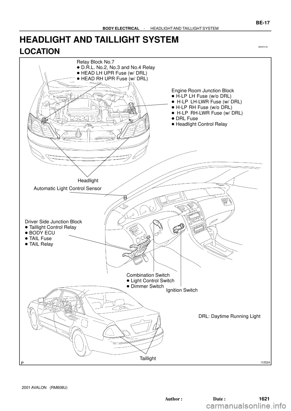
Relay Block No.7
� D.R.L. No.2, No.3 and No.4 Relay
� HEAD LH UPR Fuse (w/ DRL)
� HEAD RH UPR Fuse (w/ DRL)
Engine Room Junction Block
� H-LP LH Fuse (w/o DRL)
� H-LP LH-LWR Fuse (w/ DRL)
� H-LP RH Fuse (w/o DRL)
� H-LP RH-LWR Fuse (w/ DRL)
� DRL Fuse
� Headlight Control Relay
Headlight
Driver Side Junction Block
� Taillight Control Relay
� BODY ECU
� TAIL Fuse
� TAIL Relay
Ignition Switch
Taillight
Combination Switch
� Light Control Switch
� Dimmer Switch
Automatic Light Control Sensor
DRL: Daytime Running Light
- BODY ELECTRICALHEADLIGHT AND TAILLIGHT SYSTEM
BE-17
1621 Author�: Date�:
2001 AVALON (RM808U)
HEADLIGHT AND TAILLIGHT SYSTEM
LOCATION
Page 308 of 1897

COMBINATION METER (Meter, Gauges and Illumination):
SymptomSuspect AreaSee page
Tachometer, Fuel Gauge and Engine Cool")
BE-4
- BODY ELECTRICALTROUBLESHOOTING
1608 Author�: Date�:
2001 AVALON (RM808U)
COMBINATION METER (Meter, Gauges and Illumination):
SymptomSuspect AreaSee page
Tachometer, Fuel Gauge and Engine Coolant Temperature Gauge
do not operate.
1. ECU-B Fuse
2. ECU-IG No. 2 Fuse
3. Meter Circuit Plate
4. Wire Harness
5. Multi Display-
-
BE-43
-
-
Speedometer does not operate.
1. Vehicle Speed Sensor (ABS - ECU)
2. Meter Circuit Plate
3. Wire Harness
4. Multi DisplayBE-53
BE-43
-
-
Tachometer does not operate.
1. EFI - ECU
2. Meter Circuit Plate
3. Wire Harness
4. Multi Display-
BE-43
-
-
Fuel Gauge does not operate or abnormal operation.
1. Fuel Receiver Gauge
2. Fuel Sender Gauge
3. Meter Circuit Plate
4. Wire HarnessBE-53
BE-53
BE-43
-
Engine Coolant Temperature Gauge does not operate or abnormal
operation.
1. Engine Coolant Temperature Receiver Gauge
2. Engine Coolant Temperature Sender Gauge
3. Meter Circuit Plate
4. Wire HarnessBE-53
BE-53
BE-43
-
All illumination lights do not light up.
1. Bulb
2. PANEL Fuse
3. Light Control Rheostat
4. Wire Harness-
-
BE-53
-
Brightness does not change even when rheostat turned.
1. Bulb
2. Rheostat
3. Wire Harness-
-
-
Only one illumination light does not light up.1. Bulb
2. Wire Harness-
-
COMBINATION METER (Warning Lights):
SymptomSuspect AreaSee page
Warning lights do not light up. (Except Discharge, Open Door and
SRS)
1. Bulb
2. GAUGE No. 1 Fuse
3. Meter Circuit Plate
4. Wire Harness-
-
BE-53
-
Low Oil Pressure warning light does not light up.
1. Multi Display
2. Bulb
3. Low Oil Pressure Warning Switch
4. Meter Circuit Plate
5. Wire Harness-
-
BE-53
BE-43
-
Fuel Level warning light does not light up.
1. Multi Display
2. Bulb
3. Fuel Sender Gause
4. Meter Circuit Plate
5. Wire Harness-
-
BE-53
BE-43
-
ABS warning light does not light up.
1. Bulb
2. ABS ECU
3. Wire Harness-
DI-210
-
Page 634 of 1897
DI-213
369 Author�: Date�:
2001 AVALON (RM808U)
(d)")
BR3890
F02201
DLC1
Ts E
1
Tc
BR3904
0.13 sec. 0.12 sec.
ON
OFF
- DIAGNOSTICSANTI-LOCK BRAKE SYSTEM WITH ELECTRONIC
BRAKE FORCE DISTRIBUTION (EBD)DI-213
369 Author�: Date�:
2001 AVALON (RM808U)
(d) Clear the DTC.
(1) Using SST, connect terminals Tc and E
1 of DLC1.
SST 09843-18020
(2) Turn the ignition switch ON.
(3) Clear the DTC stored in ECU by depressing the
brake pedal 8 times or more within 5 seconds.
(4) Check that the warning light shows the normal
code.
(5) Remove the SST from the terminals of DLC1.
SST 09843-18020
HINT:
Cancellation cannot be done by removing the battery cable or
ECU-IG fuse.
2. SPEED SENSOR SIGNAL CHECK (TEST MODE)
(a) Check the sensor signal.
(1) Using SST, connect terminals Ts and E
1 of DLC1.
SST 09843-18020
(2) Start the engine.
(3) Check that the ABS warning light blinks.
HINT:
If the ABS warning light does not blink, inspect the ABS warning
light circuit (See page DI-243).
(4) Drive vehicle straight forward.
(5) Drive vehicle at a speed faster than 45 km/h (28
mph) for several seconds.
HINT:
If the brake is applied during the check, the check routine must
be started again.
(6) Stop the vehicle.
(7) Using SST, connect terminals Tc and E
1 of DLC1.
SST 09843-18020
(8) Read the number of blinks of the ABS warning light.
HINT:
�See the list of DTC shown on the next page.
�If every sensor is normal, a normal code is output (A cycle
of 0.25 sec. ON and 0.25 sec. OFF is repeated).
�If 2 or more malfunction codes are identified at the same
time, the lowest numbered code will be displayed 1st.
Page 683 of 1897

INSPECTION PROCEDURE
HINT:
Start the inspection from step 1, in case of using the TOYO")
F07902
PMCE2
- DIAGNOSTICSABS WITH EBD & BA & TRAC & VSC SYSTEM
DI-301
457 Author�: Date�:
2001 AVALON (RM808U)
INSPECTION PROCEDURE
HINT:
Start the inspection from step 1, in case of using the TOYOTA hand-held tester and start from step 2, in case
of not using the TOYOTA hand-held tester.
1 Check output value of the master cylinder pressure sensor.
PREPARATION:
(a) Connect the TOYOTA hand-held tester to the DLC3.
(b) Turn the ignition switch ON and push the TOYOTA hand-held tester main switch ON.
(c) Select the DATALIST mode on the TOYOTA hand-held tester.
CHECK:
Check that the brake fluid pressure value of the master cylinder pressure sensor displayed on the TOYOTA
hand-held tester is changing when depressing the brake pedal.
OK:
Brake fluid pressure value must be changing.
OK Go to step 4.
NG
2 Check master cylinder pressure sensor.
PREPARATION:
Install LSPV gauge to the front caliper bleeder plug portion, and
bleed the air from LSPV gauge.
SST 09709-29018
CHECK:
Start the engine and depress the brake pedal, then check the
relation between the fluid pressure and voltage of PMC and E2
terminals of the master cylinder pressure sensor with connector
still connected.
OK:
Front brake caliper fluid pressureVoltage
0 kPa (0 Kgf/cm2, 0 psi)0.44 - 0.76 V
5,883 kPa (60 kgf/cm2, 853 psi)1.34 - 1.66 V
11,768 kPa (120 kgf/cm2, 1,706 psi)2.24 - 2.56 V
HINT:
Voltage between terminals VCM and E2: 4.7 - 5.3 V
NG Replace master cylinder pressure sensor.
OK
Page 701 of 1897

DTC Normal Code Malfunction in ECM
CIRCUIT DESCRIPTION
If any trouble occurs in the ECM control sys")
- DIAGNOSTICSABS WITH EBD & BA & TRAC & VSC SYSTEM
DI-317
473 Author�: Date�:
2001 AVALON (RM808U)
DTC Normal Code Malfunction in ECM
CIRCUIT DESCRIPTION
If any trouble occurs in the ECM control system, the ECU prohibits ABS & VSC control.
DTC No.DTC Detecting ConditionTrouble Area
Normal Code
Conditions 1., 2,. 3, or 4,continue for 5 sec. or more:
1. Engine malfunction signal is sent from ECM.
2. Shift malfunction signal is sent from ECM
3. The shift position is other than P and N range input volt-
age is 8 V or more.
4. The shift position is PN or rev and D range input voltage
is 8 V or more.�ECM circuit
�ECM
�Brake fluid level
�Brake fluid level warning switch circuit
�Steering angle sensor
�ABS & BA & TRAC & VSC ECU
INSPECTION PROCEDURE
1 Is DTC out put for ECM?
Check DTC on page DI-3.
YES Repair engine control system according to the
output code.
NO
2 Check the DTC for the ABS and VSC (See page DI-252).
*1 Repair ABS and VSC control system according
to the code output.
*2
Check and replace translate ECU.
*1: Output NG code except for DTC of VSC system C1301/42
*2: Output NG code DTC of VSC system C1301/42 only
DI6OF-03
Page 723 of 1897
DI6NU-01
F07883
ABS Warning Light
VSC Warning Light
VSC OFF Indicator Light
SLIP Indicator Light
BRAKE Warning Light
DLC2Rear Speed Sensor
Sensor Rotor
Brake Actuator
ABS & BA & TRAC & VSC ECU
VSC OFF Switch Front Speed Sensor
DLC1
ABS Solenoid RelayABS Motor Relay
Room R/B No. 8 Engine
Precharge PumpMaster Cylinder
Pressure Sensor
Parking Brake Switch
Stop Light Switch
Translate ECU
Front Speed Sensor
Sensor Rotor
Sensor Rotor
Rear Speed Sensor
DLC3
Steering Angle Sensor
Yaw Rate Sensor
(Including Deceleration Sensor)
Active Lamp Relay
- DIAGNOSTICSABS WITH EBD & BA & TRAC & VSC SYSTEM
DI-261
417 Author�: Date�:
2001 AVALON (RM808U)
PARTS LOCATION
Page 727 of 1897

72 67
ON
OFF
0.5 sec. 0.5 sec. 0.5 sec. 0.5 sec.1.5 sec.
2.5 sec.4 sec.
Repeat
- DIAGNOSTICSABS WIT")
F02201
DLC1
TsTc E
1
BR3904
0.13 sec. 0.13 sec.
ON
OFF
BR3893
Malfunction Code (Example Code 72, 76)
72 67
ON
OFF
0.5 sec. 0.5 sec. 0.5 sec. 0.5 sec.1.5 sec.
2.5 sec.4 sec.
Repeat
- DIAGNOSTICSABS WITH EBD & BA & TRAC & VSC SYSTEM
DI-255
411 Author�: Date�:
2001 AVALON (RM808U)
2. SPEED SENSOR SIGNAL CHECK (TEST MODE)
(a) In case of not using TOYOTA hand-held tester:
Check the sensor signal.
(1) Turn the ignition switch OFF.
(2) Using SST, connect terminals Ts and E
1 of DLC1.
SST 09843-18020
(3) Start the engine.
(4) Check that the ABS warning light blinks.
HINT:
If the ABS warning light does not blink, inspect the ABS warning
light circuit (See page DI-325).
(5) Drive vehicle straight forward.
Drive vehicle at a speed faster than 45 km/h (28
mph) for several seconds.
HINT:
The sensor check may not be completed if the front wheels are
spun or the steering wheel is steered during this check.
(6) Stop the vehicle.
(7) Using SST, connect terminals Tc and E
1 of DLC1.
SST 09843-18020
(8) Read the number of blinks of the ABS warning light.
HINT:
�See the list of DTC shown on the next page.
�If every sensor is normal, a normal code is output (A cycle
of 0.25 sec. ON and 0.25 sec. OFF is repeated).
�If 2 or more malfunction codes are identified at the same
time, the lowest numbered code will be displayed 1st.
(9) After doing the check, disconnect the SST from ter-
minals Ts and E
1, Tc and E1 of DLC1, and turn the
ignition switch OFF.
SST 09843-18020
Page 728 of 1897

(b) In case of using TOYOTA hand")
F07887
TOYOTA Hand-
held Tester
DLC3
F19119
DLC1
Ts E1
DLC3
CG
Ts
DI-256
- DIAGNOSTICSABS WITH EBD & BA & TRAC & VSC SYSTEM
412 Author�: Date�:
2001 AVALON (RM808U)
(b) In case of using TOYOTA hand-held tester:
Check the sensor signal.
(1) Hook up the TOYOTA hand- held tester to the
DLC3.
(2) Do step (3) - (6) on the previous page.
(3) Read the DTC by following the prompts on the tes-
ter screen.
HINT:
Please refer to the TOYOTA hand-held tester operator's manu-
al for further details.
DTC of speed sensor check function:
Code No.DiagnosisTrouble Area
C1271 / 71Low output voltage of right front speed sensor
�Right front speed sensor
�Sensor installation
�Right front speed sensor rotor
C1272 / 72Low output voltage of left front speed sensor
�Left front speed sensor
�Sensor installation
�Left front speed sensor rotor
C1273 / 73Low output voltage of right rear speed sensor
�Right rear speed sensor
�Sensor installation
�Right rear speed sensor rotor
C1274 / 74Low output voltage of left rear speed sensor
�Left rear speed sensor
�Sensor installation
�Left rear speed sensor rotor
C1275 / 75Abnormal change in output signal of right front speed sen-
sorRight front speed sensor rotor
C1276 / 76Abnormal change in output signal of left front speed sensorLeft front speed sensor rotor
C1277 / 77Abnormal change in output signal of right rear speed sensorRight rear speed sensor rotor
C1278 / 78Abnormal change in output signal of left rear speed sensorLeft rear speed sensor rotor
3. STEERING ANGLE SENSOR ZERO POINT CALIBRA-
TION
NOTICE:
Make sure to perform steering angle sensor zero point cal-
ibration when:
�Replacing the steering angle sensor or ECU.
�Adjusting the front wheel alignment of the steering
wheel center point in accordance with removal and
installation or replacement of the suspension, axle or
steering parts.
(a) Using the SST, connect terminals Ts and E
1 of DLC1 or
Ts and CG of DLC3
.
SST DLC1: 09843-18020
DLC3: 09843-18040
(b) Turn the ignition switch to the ON position, without start-
ing the engine.
(c) Make sure the steering wheel off center angle is within 3
degrees of center before attempting calibration.