Page 224 of 1897
I03099
BE0B4-04
- BODY ELECTRICALENGINE IMMOBILISER SYSTEM
BE-181
1785 Author�: Date�:
2001 AVALON (RM808U)
INSPECTION
INSPECTION TRANSPONDER KEY COIL CONTINUITY
Check that continuity exists between terminal 1 and 2.
If continuity is not as specified, replace the coil.
Page 225 of 1897
BE0B3-1 1
I12540
Driver Side Junction Block
� IGN Relay
Ignition Switch Assembly
� Transponder Key Amplifier
� Transponder Key Coil
� Key Unlock Warning SwitchEngine Room Junction Block
� EFI No. 2 Fuse
ECM
BE-180
- BODY ELECTRICALENGINE IMMOBILISER SYSTEM
1784 Author�: Date�:
2001 AVALON (RM808U)
LOCATION
Page 308 of 1897

COMBINATION METER (Meter, Gauges and Illumination):
SymptomSuspect AreaSee page
Tachometer, Fuel Gauge and Engine Cool")
BE-4
- BODY ELECTRICALTROUBLESHOOTING
1608 Author�: Date�:
2001 AVALON (RM808U)
COMBINATION METER (Meter, Gauges and Illumination):
SymptomSuspect AreaSee page
Tachometer, Fuel Gauge and Engine Coolant Temperature Gauge
do not operate.
1. ECU-B Fuse
2. ECU-IG No. 2 Fuse
3. Meter Circuit Plate
4. Wire Harness
5. Multi Display-
-
BE-43
-
-
Speedometer does not operate.
1. Vehicle Speed Sensor (ABS - ECU)
2. Meter Circuit Plate
3. Wire Harness
4. Multi DisplayBE-53
BE-43
-
-
Tachometer does not operate.
1. EFI - ECU
2. Meter Circuit Plate
3. Wire Harness
4. Multi Display-
BE-43
-
-
Fuel Gauge does not operate or abnormal operation.
1. Fuel Receiver Gauge
2. Fuel Sender Gauge
3. Meter Circuit Plate
4. Wire HarnessBE-53
BE-53
BE-43
-
Engine Coolant Temperature Gauge does not operate or abnormal
operation.
1. Engine Coolant Temperature Receiver Gauge
2. Engine Coolant Temperature Sender Gauge
3. Meter Circuit Plate
4. Wire HarnessBE-53
BE-53
BE-43
-
All illumination lights do not light up.
1. Bulb
2. PANEL Fuse
3. Light Control Rheostat
4. Wire Harness-
-
BE-53
-
Brightness does not change even when rheostat turned.
1. Bulb
2. Rheostat
3. Wire Harness-
-
-
Only one illumination light does not light up.1. Bulb
2. Wire Harness-
-
COMBINATION METER (Warning Lights):
SymptomSuspect AreaSee page
Warning lights do not light up. (Except Discharge, Open Door and
SRS)
1. Bulb
2. GAUGE No. 1 Fuse
3. Meter Circuit Plate
4. Wire Harness-
-
BE-53
-
Low Oil Pressure warning light does not light up.
1. Multi Display
2. Bulb
3. Low Oil Pressure Warning Switch
4. Meter Circuit Plate
5. Wire Harness-
-
BE-53
BE-43
-
Fuel Level warning light does not light up.
1. Multi Display
2. Bulb
3. Fuel Sender Gause
4. Meter Circuit Plate
5. Wire Harness-
-
BE-53
BE-43
-
ABS warning light does not light up.
1. Bulb
2. ABS ECU
3. Wire Harness-
DI-210
-
Page 568 of 1897
CO02K-03
- COOLINGCOOLANT
CO-1
1194 Author�: Date�:
2001 AVALON (RM808U)
COOLANT
INSPECTION
1. CHECK ENGINE COOLANT LEVEL AT RADIATOR RESERVOIR
The engine coolant level should be between the ºLOWº and ºFULLº lines, when the engine is cold.
If low, check for leaks and add ''Toyota Long Life Coolantº or Equivalent up to the ºFULLº line.
2. CHECK ENGINE COOLANT QUALITY
(a) Remove the radiator cap from the water outlet.
CAUTION:
To avoid the danger of being burned, do not remove the radiator cap while the engine and radiator
are still hot, as fluid and steam can be blown out under pressure.
(b) There should not be any excessive deposits of rust or scale around the radiator cap or water outlet
filler hole, and the coolant should be free from oil.
If excessively dirty, clean the coolant passages and replace the coolant.
(c) Reinstall the radiator cap.
Page 578 of 1897
CO02W-03
B09039
Radiator
No.1 ECT Switch
No.2 Cooling Fan Connector
Upper Radiator
Support
Upper Radiator
HoseNo.1 Cooling Fan Connector
No.1 ECT Switch Wire Connector
Radiator Assembly
Lower Radiator
Support� O-Ring
A/T Oil Cooler Hose
No.3 Engine
Room Relay Block No.1 Cooling Fan
� Non-reusable part � O-Ring
Drain Plug
Lower Radiator
Hose
No.2 Cooling Fan
Battery
Insulator
Battery
Battery
Tray Hold-Down
Clamp
Engine Under Cover
- COOLINGRADIATOR
CO-15
1208 Author�: Date�:
2001 AVALON (RM808U)
COMPONENTS
Page 587 of 1897

REMOVAL
HINT:
At the time of installation, please refer to the following items.
�Start the engine, and check for coo")
CO0WT-01
B09040
- COOLINGRADIATOR
CO-17
1210 Author�: Date�:
2001 AVALON (RM808U)
REMOVAL
HINT:
At the time of installation, please refer to the following items.
�Start the engine, and check for coolant and A/T fluid
leaks.
�Check the A/T fluid level (See page DI-160).
1. REMOVE BATTERY AND BATTERY TRAY
2. REMOVE ENGINE UNDER COVER
3. DRAIN ENGINE COOLANT
4. DISCONNECT NO.3 ENGINE ROOM RELAY BLOCK
FROM RADIATOR
5. DISCONNECT NO.1 COOLING FAN CONNECTOR
6. DISCONNECT WIRE CLAMPS FROM NO.1 FAN
SHROUD
7. DISCONNECT NO.2 COOLING FAN CONNECTOR
8. DISCONNECT NO.1 ECT SWITCH WIRE CONNECTOR
9. DISCONNECT WIRE CLAMPS FROM NO.2 FAN
SHROUD
10. DISCONNECT UPPER RADIATOR HOSE FROM RA-
DIATOR
11. DISCONNECT LOWER RADIATOR HOSE FROM RA-
DIATOR
12. DISCONNECT A/T OIL COOLER HOSES FROM RA-
DIATOR
13. REMOVE RADIATOR AND COOLING FANS AS-
SEMBLY
(a) Remove the 2 bolts and 2 upper supports.
Torque: 12.8 N´m (130 kgf´cm, 9 ft´lbf)
(b) Lift out the radiator, and remove the radiator and cooling
fans assembly.
(c) Remove the 2 lower supports.
14. REMOVE NO.1 ECT SWITCH
15. REMOVE NO.1 COOLING FAN FROM RADIATOR
Remove the 2 bolts and cooling fan.
Torque: 5.0 N´m (50 kgf´cm, 44 in.´lbf)
16. REMOVE NO.2 COOLING FAN FROM RADIATOR
Remove the 2 bolts and cooling fan.
Torque: 5.0 N´m (50 kgf´cm, 44 in.´lbf)
Page 596 of 1897
CO02P-03
P12942
CO-8
- COOLINGWATER PUMP
1201 Author�: Date�:
2001 AVALON (RM808U)
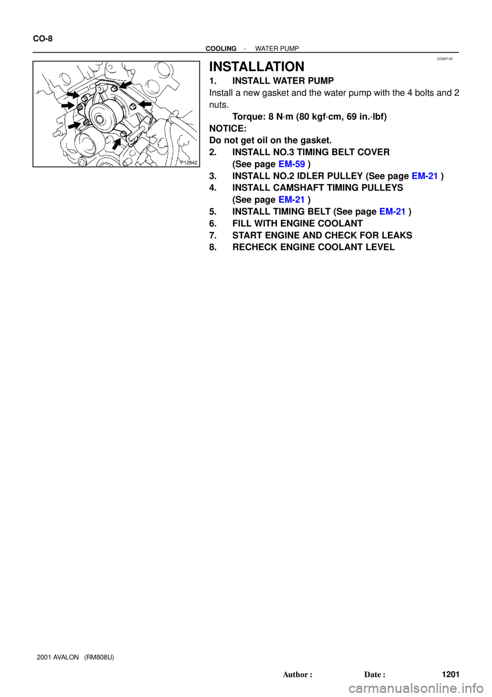
INSTALLATION
1. INSTALL WATER PUMP
Install a new gasket and the water pump with the 4 bolts and 2
nuts.
Torque: 8 N´m (80 kgf´cm, 69 in.´lbf)
NOTICE:
Do not get oil on the gasket.
2. INSTALL NO.3 TIMING BELT COVER
(See page EM-59)
3. INSTALL NO.2 IDLER PULLEY (See page EM-21)
4. INSTALL CAMSHAFT TIMING PULLEYS
(See page EM-21)
5. INSTALL TIMING BELT (See page EM-21)
6. FILL WITH ENGINE COOLANT
7. START ENGINE AND CHECK FOR LEAKS
8. RECHECK ENGINE COOLANT LEVEL
Page 666 of 1897

3")
F07892
ECU ABS
Solenoid
Relay
Brake
Actuator3 Engine Room R/B No. 8
5 25
49 52
6 2650 533 4
54
55
DI-284
- DIAGNOSTICSABS WITH EBD & BA & TRAC & VSC SYSTEM
440 Author�: Date�:
2001 AVALON (RM808U)
3 Check continuity between terminal 3 of engine room R/B No. 8 (for ABS solenoid
relay) and each solenoid terminal of ABS & BA & TRAC & VSC ECU.
PREPARATION:
Disconnect the connector from the ABS & BA & TRAC & VSC
ECU.
CHECK:
Check continuity between terminal 3 of engine room R/B No. 8
and each terminal, 3, 4, 5, 6, 25, 26, 49, 50, 52, 53, 54 and 55
of ECU harness side connector.
OK:
Continuity
HINT:
Resistance of each solenoid coil.
SFLH (5), SRRH (6), SFRH (26), SMC1 (49), SMC2 (50), SRLH
(53): 8 - 9.1 W
SFLR (3), SRRR (4), SRLR (25), SRC2 (52), SRC1 (54), SFRR
(55): 4.0 - 4.6 W
NG Repair or replace harness or brake actuator.
OK
4 Check for open and short circuit in harness and connector between ABS sole-
noid relay and ABS & BA & TRAC & VSC ECU (See page IN-30).
NG Repair or replace harness or connector.
OK
If the same code is still output after the DTC is deleted, check the contact condition of each con-
nection. If the connections are normal, the ECU may be defective.