Page 330 of 1897

BE-100
- BODY ELECTRICALWIRELESS DOOR LOCK CONTROL SYSTEM
1704 Author�: Date�:
2001 AVALON (RM808U)
MPX body performs operates LOCK-UNLOCK operation 5 times at a 1 sec.
interval to inform the operator that prohibition mode has been selected.
Press again either of switches on the transmitter.
MPX body ECU automatically performs LOCK-UNLOCK operation once or
twice at a 1 sec. interval to inform the operator that it has received the signal
from the transmitter.
LOCK-UNLOCK occurs once
LOCK-UNLOCK occurs twice Registration of recognition code is completed
Registration of recognition code has not been completed.
� Recognition code received first time and second time did not match.
Proceed to continue registration
If even one of the following conditions is satisfied, registration of recognition
codes in completed.
� 40 secs. elapses since the MPX body ECU response.
� The driver's door is closed.
� The key plate is inserted in the ignition key cylinder.
� 4 types recognition codes are registration at one time.
Registration of recognition codes (add mode or rewrite mode) is completed.
Within
3 secs. Within
40 secs.
ON
LOCK
Approx.
1 sec.Approx.
1 sec.
When prohibition
mode is selected.
Press the lock and unlock switches on the transmitter simultaneously within 1.5 sec.
If they are not performed, the mode returns to the normal mode, then start with
ºStart registration of recognition codeº.
Proceed to finish registration
Within 40 secs.
Within 3 secs.
Page 333 of 1897
BO5229
BO-46
- BODYBODY OUTSIDE MOULDING
1831 Author�: Date�:
2001 AVALON (RM808U)
(c) Align the bosess with their corresponding holes in the
body, and press firmly on the moulding.
NOTICE:
Do not apply excessive force onto the moulding, but steady
pressure with your thumbs.
Page 377 of 1897

BO2PU-02
H12194: Specified torqueN´m (kgf´cm, ft´lbf)
AA
KK
K
K
K
K
K
K
B
L
E
G
GG
G
GG
G
GGI
C
C
C
C
K
K
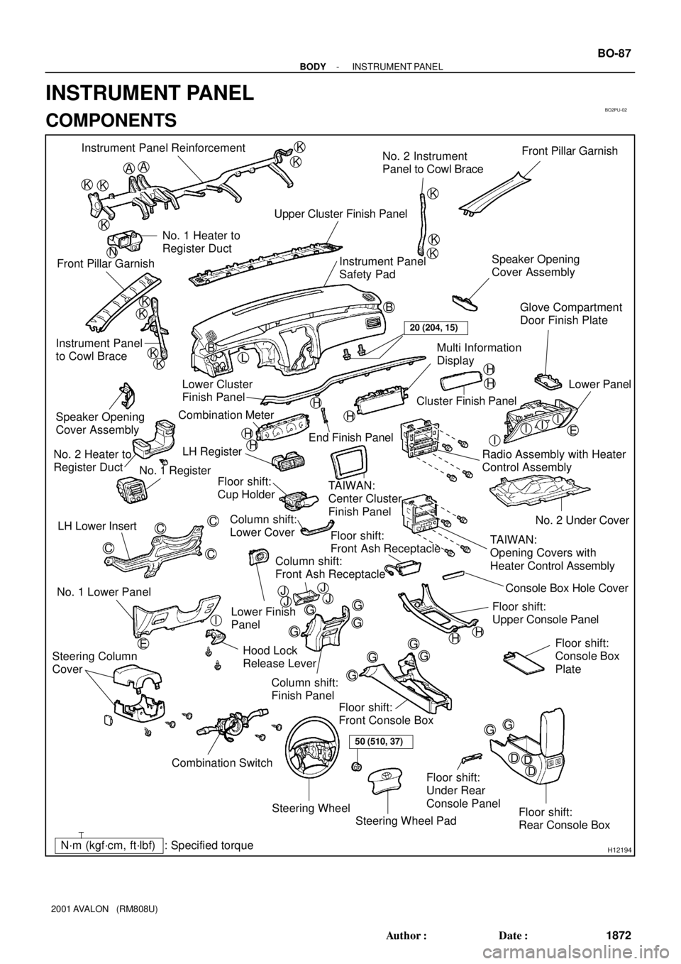
KKB Instrument Panel Reinforcement
No. 2 Instrument
Panel to Cowl BraceFront Pillar Garnish
Upper Cluster Finish Panel
Instrument Panel
Safety Pad Front Pillar GarnishNo. 1 Heater to
Register Duct
Instrument Panel
to Cowl BraceSpeaker Opening
Cover Assembly
H
H
H
H
H
H
III
G
D EDD
Steering Wheel
Floor shift:
Rear Console Box Floor shift:
Front Console Box
Combination Switch No. 1 Lower PanelLH Lower Insert
Column shift:
Finish Panel Hood Lock
Release LeverNo. 2 Under Cover
Floor shift:
Console Box
Plate
Steering Wheel Pad Steering Column
Cover
Floor shift:
Front Ash Receptacle
Floor shift:
Upper Console PanelLower Finish
Panel Column shift:
Lower Cover LH Register
TAIWAN:
Center Cluster
Finish Panel
TAIWAN:
Opening Covers with
Heater Control Assembly Radio Assembly with Heater
Control AssemblyLower Panel
Cluster Finish Panel
End Finish Panel Combination Meter Lower Cluster
Finish PanelGlove Compartment
Door Finish Plate
Speaker Opening
Cover Assembly
No. 2 Heater to
Register Duct
No. 1 Register
Floor shift:
Cup Holder
Multi Information
Display
Floor shift:
Under Rear
Console Panel
I
HH
50 (510, 37)
20 (204, 15)
N
JJJJConsole Box Hole Cover
Column shift:
Front Ash Receptacle
- BODYINSTRUMENT PANEL
BO-87
1872 Author�: Date�:
2001 AVALON (RM808U)
INSTRUMENT PANEL
COMPONENTS
Page 379 of 1897
H12196
Shape Size
ù = 8
(0.31)
L = 20
(0.79)Shape Size Shape Size
ù = 6
(0.24)
L = 20
(0.79)
ù = 6
(0.24)
L = 16
(0.63)ù = 6
(0.24)
L = 18
(0.71)ù = 6
(0.24)
L = 20
(0.79)
L = 16
(0.63) ù = 6
(0.24)
ù = 5.22
(0.2055)
L = 20
(0.79)ù = 5.22
(0.2055)
L = 16
(0.63)ù = 5
(0.20)
L = 16
(0.63)
ù = 8
(0.31)mm (in.)
ù = 6
(0.24)ù = 6
(0.24)ù = 6
(0.24) ù = 5
(0.20)
L = 14
(0.55)
- BODYINSTRUMENT PANEL
BO-89
1874 Author�: Date�:
2001 AVALON (RM808U)
HINT:
Screw shapes and sizes are indicated in the table below. The codes (ºAº - ºNº) correspond to those indicated
on the previous page.
Page 388 of 1897

BO2PU-02
H12194: Specified torqueN´m (kgf´cm, ft´lbf)
AA
KK
K
K
K
K
K
K
B
L
E
G
GG
G
GG
G
GGI
C
C
C
C
K
K
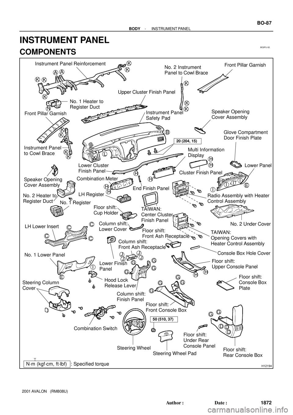
KKB Instrument Panel Reinforcement
No. 2 Instrument
Panel to Cowl BraceFront Pillar Garnish
Upper Cluster Finish Panel
Instrument Panel
Safety Pad Front Pillar GarnishNo. 1 Heater to
Register Duct
Instrument Panel
to Cowl BraceSpeaker Opening
Cover Assembly
H
H
H
H
H
H
III
G
D EDD
Steering Wheel
Floor shift:
Rear Console Box Floor shift:
Front Console Box
Combination Switch No. 1 Lower PanelLH Lower Insert
Column shift:
Finish Panel Hood Lock
Release LeverNo. 2 Under Cover
Floor shift:
Console Box
Plate
Steering Wheel Pad Steering Column
Cover
Floor shift:
Front Ash Receptacle
Floor shift:
Upper Console PanelLower Finish
Panel Column shift:
Lower Cover LH Register
TAIWAN:
Center Cluster
Finish Panel
TAIWAN:
Opening Covers with
Heater Control Assembly Radio Assembly with Heater
Control AssemblyLower Panel
Cluster Finish Panel
End Finish Panel Combination Meter Lower Cluster
Finish PanelGlove Compartment
Door Finish Plate
Speaker Opening
Cover Assembly
No. 2 Heater to
Register Duct
No. 1 Register
Floor shift:
Cup Holder
Multi Information
Display
Floor shift:
Under Rear
Console Panel
I
HH
50 (510, 37)
20 (204, 15)
N
JJJJConsole Box Hole Cover
Column shift:
Front Ash Receptacle
- BODYINSTRUMENT PANEL
BO-87
1872 Author�: Date�:
2001 AVALON (RM808U)
INSTRUMENT PANEL
COMPONENTS
Page 390 of 1897
H12196
Shape Size
ù = 8
(0.31)
L = 20
(0.79)Shape Size Shape Size
ù = 6
(0.24)
L = 20
(0.79)
ù = 6
(0.24)
L = 16
(0.63)ù = 6
(0.24)
L = 18
(0.71)ù = 6
(0.24)
L = 20
(0.79)
L = 16
(0.63) ù = 6
(0.24)
ù = 5.22
(0.2055)
L = 20
(0.79)ù = 5.22
(0.2055)
L = 16
(0.63)ù = 5
(0.20)
L = 16
(0.63)
ù = 8
(0.31)mm (in.)
ù = 6
(0.24)ù = 6
(0.24)ù = 6
(0.24) ù = 5
(0.20)
L = 14
(0.55)
- BODYINSTRUMENT PANEL
BO-89
1874 Author�: Date�:
2001 AVALON (RM808U)
HINT:
Screw shapes and sizes are indicated in the table below. The codes (ºAº - ºNº) correspond to those indicated
on the previous page.
Page 606 of 1897
DI6NC-01
F09803
ABS Actuator and ECU
+B
BAT
GND1
GND2 W-B
FL MAINFL Block
ALT
B-L
BatteryA717
A718
A719
A716 L
L
W-B
EE5 5
12 B
10 2F
42F 12H
12G
W-B
ED 1
F8 1
F6
BABS Engine Room R/B No. 5
Engine Room J/B
- DIAGNOSTICSANTI-LOCK BRAKE SYSTEM WITH ELECTRONIC
BRAKE FORCE DISTRIBUTION (EBD)DI-219
375 Author�: Date�:
2001 AVALON (RM808U)
CIRCUIT INSPECTION
DTC 11 ABS Solenoid Relay Circuit
CIRCUIT DESCRIPTION
This relay supplies power to each ABS solenoid. After the ignition switch is turned ON, if the initial check is
OK, the relay goes on.
DTC No.DTC Detecting ConditionTrouble Area
11
When any of the following 1. through 3. is detected:
1. 3 or more solenoids are shown faulty in response and
simultaneously solenoid supply voltage is detected
faulty.
2. Solenoid relay will not be switched OFF.
3. Solenoid relay is frozen in spite of its high valve relay
supply voltage.
�ABS solenoid relay
�ABS solenoid relay circuit
WIRING DIAGRAM
Page 630 of 1897

DI6N8-01
- DIAGNOSTICSANTI-LOCK BRAKE SYSTEM WITH ELECTRONIC
BRAKE FORCE DISTRIBUTION (EBD)DI-215
371 Author�: Date�:
2001 AVALON (RM808U)
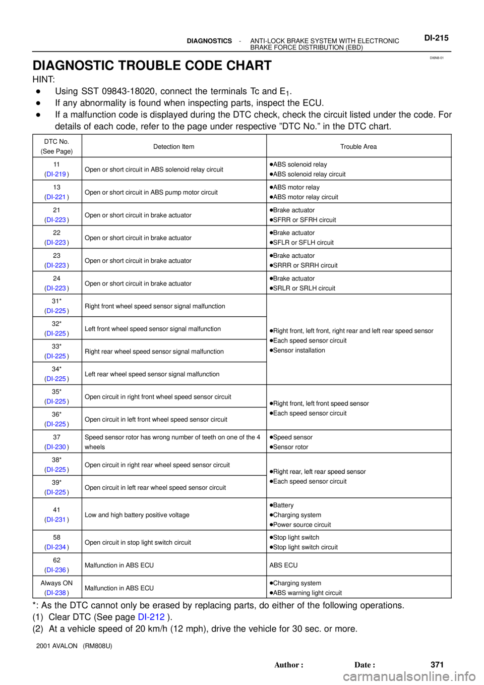
DIAGNOSTIC TROUBLE CODE CHART
HINT:
�Using SST 09843-18020, connect the terminals Tc and E1.
�If any abnormality is found when inspecting parts, inspect the ECU.
�If a malfunction code is displayed during the DTC check, check the circuit listed under the code. For
details of each code, refer to the page under respective ºDTC No.º in the DTC chart.
DTC No.
(See Page)Detection ItemTrouble Area
11
(DI-219)Open or short circuit in ABS solenoid relay circuit�ABS solenoid relay
�ABS solenoid relay circuit
13
(DI-221)Open or short circuit in ABS pump motor circuit�ABS motor relay
�ABS motor relay circuit
21
(DI-223)Open or short circuit in brake actuator�Brake actuator
�SFRR or SFRH circuit
22
(DI-223)Open or short circuit in brake actuator�Brake actuator
�SFLR or SFLH circuit
23
(DI-223)Open or short circuit in brake actuator�Brake actuator
�SRRR or SRRH circuit
24
(DI-223)Open or short circuit in brake actuator�Brake actuator
�SRLR or SRLH circuit
31*
(DI-225)Right front wheel speed sensor signal malfunction
32*
(DI-225)Left front wheel speed sensor signal malfunction�Right front, left front, right rear and left rear speed sensor
Eh d i it33*
(DI-225)Right rear wheel speed sensor signal malfunction
�Each speed sensor circuit
�Sensor installation
34*
(DI-225)Left rear wheel speed sensor signal malfunction
35*
(DI-225)Open circuit in right front wheel speed sensor circuit�Right front, left front speed sensor
36*
(DI-225)Open circuit in left front wheel speed sensor circuit
�Right front, left front s eed sensor
�Each speed sensor circuit
37
(DI-230)Speed sensor rotor has wrong number of teeth on one of the 4
wheels�Speed sensor
�Sensor rotor
38*
(DI-225)Open circuit in right rear wheel speed sensor circuit�Right rear, left rear speed sensor
39*
(DI-225)Open circuit in left rear wheel speed sensor circuit
�Right rear, left rear s eed sensor
�Each speed sensor circuit
41
(DI-231)Low and high battery positive voltage
�Battery
�Charging system
�Power source circuit
58
(DI-234)Open circuit in stop light switch circuit�Stop light switch
�Stop light switch circuit
62
(DI-236)Malfunction in ABS ECUABS ECU
Always ON
(DI-238)Malfunction in ABS ECU�Charging system
�ABS warning light circuit
*: As the DTC cannot only be erased by replacing parts, do either of the following operations.
(1) Clear DTC (See page DI-212).
(2) At a vehicle speed of 20 km/h (12 mph), drive the vehicle for 30 sec. or more.