Page 1783 of 3833
![NISSAN X-TRAIL 2001 Service Repair Manual TROUBLE DIAGNOSIS
EC-1433
[YD]
C
D
E
F
G
H
I
J
K
L
MA
EC
ENGINE CONTROL COMPONENT PARTS/CONTROL SYSTEMS APPLICATION
X: Applicable
SELF-DIAGNOSTIC MODE
Regarding items detected in “SELF-DIAG RESULTS� NISSAN X-TRAIL 2001 Service Repair Manual TROUBLE DIAGNOSIS
EC-1433
[YD]
C
D
E
F
G
H
I
J
K
L
MA
EC
ENGINE CONTROL COMPONENT PARTS/CONTROL SYSTEMS APPLICATION
X: Applicable
SELF-DIAGNOSTIC MODE
Regarding items detected in “SELF-DIAG RESULTS�](/manual-img/5/57405/w960_57405-1782.png)
TROUBLE DIAGNOSIS
EC-1433
[YD]
C
D
E
F
G
H
I
J
K
L
MA
EC
ENGINE CONTROL COMPONENT PARTS/CONTROL SYSTEMS APPLICATION
X: Applicable
SELF-DIAGNOSTIC MODE
Regarding items detected in “SELF-DIAG RESULTS” mode, refer to — EC-1393, "INDEX FOR DTC" .
DATA MONITOR MODE
ItemDIAGNOSTIC TEST MODE
SELF-DIAG
RESULTSDATA MONI-
TORACTIVE
TEST
ENGINE CONTROL COMPONENT PARTS
INPUTCrankshaft position sensor (TDC)××
Camshaft position sensor×
Engine coolant temperature sensor××
Vehicle speed sensor××
Fuel temperature sensor××
Accelerator pedal position sensor 1××
Accelerator pedal position sensor 2××
Accelerator pedal released position switch××
Common rail fuel pressure sensor××
Park/neutral position (PNP) switch×
Mass air flow sensor××
Battery voltage××
Power steering oil pressure switch×
Stop lamp switch×
Absolute pressure sensor××
Fuel injector adjustment resistor×
OUTPUTSuction control valve×××
Fuel injector×××
Glow relay××
Cooling fan relay×××
EGR volume control valve××
MONITOR ITEMECM
INPUT
SIG-
NALMAIN
SIG-
NALSCAN
DIAG
SUP-
PORT
MNTRCONDITION SPECIFICATION
CKPS·RPM (TDC) [rpm]××
●The engine speed computed
from the crankshaft position
sensor (TDC) signal is dis-
played.
COOLAN TEMP/S
[°C] or [°F]××
●The engine coolant tempera-
ture (determined by the signal
voltage of the engine coolant
temperature sensor) is dis-
played.When the engine coolant temper-
ature circuit is open or short, ECM
enters fail-safe mode. The engine
coolant temperature determined
by the ECM is displayed.
VHCL SPEED SE
[km/h] or [mph]××
●The vehicle speed computed
form the vehicle speed sensor
signal is displayed.
FUEL TEMP SEN [°C] or [°F]××
●The fuel temperature (deter-
mined by the signal voltage of
the fuel temperature sensor) is
displayed.
Page 1784 of 3833
![NISSAN X-TRAIL 2001 Service Repair Manual EC-1434
[YD]
TROUBLE DIAGNOSIS
ACCEL POS SEN [V]××
●The accelerator pedal position
sensor 1 signal voltage is dis-
played.
ACCEL SEN 2 [V]××
●The accelerator pedal position
sensor 2 signal v NISSAN X-TRAIL 2001 Service Repair Manual EC-1434
[YD]
TROUBLE DIAGNOSIS
ACCEL POS SEN [V]××
●The accelerator pedal position
sensor 1 signal voltage is dis-
played.
ACCEL SEN 2 [V]××
●The accelerator pedal position
sensor 2 signal v](/manual-img/5/57405/w960_57405-1783.png)
EC-1434
[YD]
TROUBLE DIAGNOSIS
ACCEL POS SEN [V]××
●The accelerator pedal position
sensor 1 signal voltage is dis-
played.
ACCEL SEN 2 [V]××
●The accelerator pedal position
sensor 2 signal voltage is dis-
played.
OFF ACCEL SW [ON/OFF]××
●indicates [ON/OFF] condition
from the accelerator pedal
released position switch signal.
ACT CR PRESS [MPa]××
●The common rail fuel pressure
(determined by the signal volt-
age of the common rail fuel
pressure sensor) is displayed.
BATTERY VOLT [V]××
●The power supply voltage of
ECM is displayed.
P/N POSI SW [ON/OFF]××
●Indicates [ON/OFF] condition
from the park/neutral position
switch signal.
START SIGNAL [ON/OFF]××
●indicates [ON/OFF] condition
from the starter signal.
PW/ST SIGNAL [ON/OFF]×
●indicates [ON/OFF] condition
from the power steering oil pres-
sure switch signal.
BRAKE SW [ON/OFF]××
●indicates [ON/OFF] condition
from the stop lamp switch sig-
nal.
IGN SW [ON/OFF]××
●Indicates [ON/OFF] condition
from ignition switch signal.
MAS AIR/FL SE [V]××
●The signal voltage of the mass
air flow sensor is displayed.
SUCTION CV [°CA]×
●Indicates [°CA] of suction con-
trol valve operating angle.
MAIN INJ WID [msec]×
●Indicates the actual fuel injec-
tion pulse width compensated
by ECM according to the input
signals.
GLOW RLY [ON/OFF]×
●The glow relay control condition
(determined by ECM according
to the input signal) is displayed.
COOLING FAN
[LOW/HI/OFF]×
●Indicates the control condition of
the cooling fans (determined by
ECM according to the input sig-
nal).
LOW ... Operates at low speed.
HI ... Operates at high speed.
OFF ... Stopped
EGR VOL CON/V [step]×
●Indicates the EGR volume con-
tro l value co mp ute d by the ECM
according to the input signals.
●The opening becomes larger as
the value increases. MONITOR ITEMECM
INPUT
SIG-
NALMAIN
SIG-
NALSCAN
DIAG
SUP-
PORT
MNTRCONDITION SPECIFICATION
Page 1918 of 3833
![NISSAN X-TRAIL 2001 Service Repair Manual EC-1568
[YD]
POWER STEERING OIL PRESSURE SWITCH
POWER STEERING OIL PRESSURE SWITCH
PFP:49761
Component DescriptionEBS003PS
The power steering oil pressure switch is attached to the power
ste NISSAN X-TRAIL 2001 Service Repair Manual EC-1568
[YD]
POWER STEERING OIL PRESSURE SWITCH
POWER STEERING OIL PRESSURE SWITCH
PFP:49761
Component DescriptionEBS003PS
The power steering oil pressure switch is attached to the power
ste](/manual-img/5/57405/w960_57405-1917.png)
EC-1568
[YD]
POWER STEERING OIL PRESSURE SWITCH
POWER STEERING OIL PRESSURE SWITCH
PFP:49761
Component DescriptionEBS003PS
The power steering oil pressure switch is attached to the power
steering high-pressure tube and detects a power steering load.
When a power steering load is detected, it signals the ECM. The
ECM adjusts the fuel injector pulse width to increase the idle speed
and adjust for the increased load.
CONSULT-II Reference Value in Data Monitor ModeEBS003PT
Specification data are reference values.
ECM Terminals and Reference ValueEBS003PZ
Specification data are reference values, and are measured between each terminal and ground.
CAUTION:
Do not use ECM ground terminals when measuring input/output voltage. Doing so may result in dam-
age to the ECM's transistor. Use a ground other than ECM terminals, such as the ground.
PBIB0375E
MONITOR ITEM CONDITION SPECIFICATION
PW/ST SIGNAL
●Engine: After warming up, idle the
engineSteering wheel is in neutral position.
(Forward direction)OFF
Steering wheel is turned. ON
TER-
MINAL
NO.WIRE
COLORITEM CONDITION DATA (DC Voltage)
E12 P/BPower steering oil pressure
switch[Engine is running]
●Steering wheel is being turnedApproximately 0V
[Engine is running]
●Steering wheel is not being turnedBATTERY VOLTAGE
(11 - 14V)
Page 1919 of 3833
POWER STEERING OIL PRESSURE SWITCH
EC-1569
[YD]
C
D
E
F
G
H
I
J
K
L
MA
EC
Wiring DiagramEBS003PU
TBWA0115E
Page 1920 of 3833
![NISSAN X-TRAIL 2001 Service Repair Manual EC-1570
[YD]
POWER STEERING OIL PRESSURE SWITCH
Diagnostic Procedure
EBS003PV
1. CHECK OVERALL FUNCTION
With CONSULT-II
1. Start engine.
2. Check “PW/ST SIGNAL” in “DATA MONITOR” mode with CON NISSAN X-TRAIL 2001 Service Repair Manual EC-1570
[YD]
POWER STEERING OIL PRESSURE SWITCH
Diagnostic Procedure
EBS003PV
1. CHECK OVERALL FUNCTION
With CONSULT-II
1. Start engine.
2. Check “PW/ST SIGNAL” in “DATA MONITOR” mode with CON](/manual-img/5/57405/w960_57405-1919.png)
EC-1570
[YD]
POWER STEERING OIL PRESSURE SWITCH
Diagnostic Procedure
EBS003PV
1. CHECK OVERALL FUNCTION
With CONSULT-II
1. Start engine.
2. Check “PW/ST SIGNAL” in “DATA MONITOR” mode with CON-
SULT-II under the following conditions.
OK or NG
OK >>INSPECTION END
NG >> GO TO 2.
2. CHECK POWER STEERING OIL PRESSURE SWITCH GROUND CIRCUIT FOR OPEN AND SHORT
1. Turn ignition switch “OFF”.
2. Disconnect power steering oil pressure switch harness connec-
tor.
3. Check harness continuity between power steering oil pressure
switch terminal 2 and engine ground. Refer to Wiring Diagram.
4. Also check harness for short to power.
OK or NG
OK >> GO TO 3.
NG >> Repair open circuit or short to power in harness or con-
nectors.
3. CHECK POWER STEERING OIL PRESSURE SWITCH INPUT SIGNAL CIRCUIT FOR OPEN AND
SHORT
1. Disconnect ECM harness connector.
2. Check harness continuity between ECM terminal E12 and power steering oil pressure switch terminal 1.
Refer to Wiring Diagram.
3. Also check harness for short to ground and short to power.
OK or NG
OK >> GO TO 4.
NG >> Repair open circuit or short to ground or short to power in harness or connectors.
4. CHECK POWER STEERING OIL PRESSURE SWITCH
Refer to EC-1571, "
Component Inspection" .
OK or NG
OK >> GO TO 5.
NG >> Replace power steering oil pressure switch.
Conditions PW/ST SIGNAL
Steering in neutral position OFF
Steering is turned ON
PBIB0434E
Continuity should exist.
PBIB0375E
Continuity should exist.
Page 1921 of 3833
POWER STEERING OIL PRESSURE SWITCH
EC-1571
[YD]
C
D
E
F
G
H
I
J
K
L
MA
EC
5.CHECK INTERMITTENT INCIDENT
Refer to EC-1441, "
TROUBLE DIAGNOSIS FOR INTERMITTENT INCIDENT" .
>>INSPECTION END
Component InspectionEBS003PW
POWER STEERING OIL PRESSURE SWITCH
1. Disconnect power steering oil pressure switch harness connector and then start engine.
2. Check continuity between power steering oil pressure switch ter-
minal 1 and 2 under the following conditions.
Removal and InstallationEBS008ZH
POWER STEERING OIL PRESSURE SWITCH
Refer to PS-34, "HYDRAULIC LINE" .
Conditions Continuity
Steering wheel is being fully turned. Yes
Steering wheel is not being turned. No
PBIB0435E
Page 2666 of 3833

TF-56
TROUBLE DIAGNOSIS
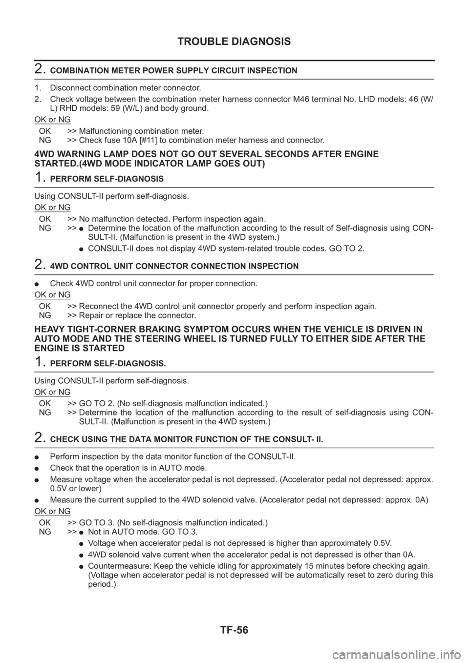
2. COMBINATION METER POWER SUPPLY CIRCUIT INSPECTION
1. Disconnect combination meter connector.
2. Check voltage between the combination meter harness connector M46 terminal No. LHD models: 46 (W/
L) RHD models: 59 (W/L) and body ground.
OK or NG
OK >> Malfunctioning combination meter.
NG >> Check fuse 10A [#11] to combination meter harness and connector.
4WD WARNING LAMP DOES NOT GO OUT SEVERAL SECONDS AFTER ENGINE
STARTED.(4WD MODE INDICATOR LAMP GOES OUT)
1. PERFORM SELF-DIAGNOSIS
Using CONSULT-II perform self-diagnosis.
OK or NG
OK >> No malfunction detected. Perform inspection again.
NG >>
●Determine the location of the malfunction according to the result of Self-diagnosis using CON-
SULT-II. (Malfunction is present in the 4WD system.)
●CONSULT-II does not display 4WD system-related trouble codes. GO TO 2.
2. 4WD CONTROL UNIT CONNECTOR CONNECTION INSPECTION
●Check 4WD control unit connector for proper connection.
OK or NG
OK >> Reconnect the 4WD control unit connector properly and perform inspection again.
NG >> Repair or replace the connector.
HEAVY TIGHT-CORNER BRAKING SYMPTOM OCCURS WHEN THE VEHICLE IS DRIVEN IN
AUTO MODE AND THE STEERING WHEEL IS TURNED FULLY TO EITHER SIDE AFTER THE
ENGINE IS STARTED
1. PERFORM SELF-DIAGNOSIS.
Using CONSULT-II perform self-diagnosis.
OK or NG
OK >> GO TO 2. (No self-diagnosis malfunction indicated.)
NG >> Determine the location of the malfunction according to the result of self-diagnosis using CON-
SULT-II. (Malfunction is present in the 4WD system.)
2. CHECK USING THE DATA MONITOR FUNCTION OF THE CONSULT- II.
●Perform inspection by the data monitor function of the CONSULT-II.
●Check that the operation is in AUTO mode.
●Measure voltage when the accelerator pedal is not depressed. (Accelerator pedal not depressed: approx.
0.5V or lower)
●Measure the current supplied to the 4WD solenoid valve. (Accelerator pedal not depressed: approx. 0A)
OK or NG
OK >> GO TO 3. (No self-diagnosis malfunction indicated.)
NG >>
●Not in AUTO mode. GO TO 3.
●Voltage when accelerator pedal is not depressed is higher than approximately 0.5V.
●4WD solenoid valve current when the accelerator pedal is not depressed is other than 0A.
●Countermeasure: Keep the vehicle idling for approximately 15 minutes before checking again.
(Voltage when accelerator pedal is not depressed will be automatically reset to zero during this
period.)
Page 2718 of 3833

FSU-12
FRONT SUSPENSION MEMBER
FRONT SUSPENSION MEMBER
PFP:54401
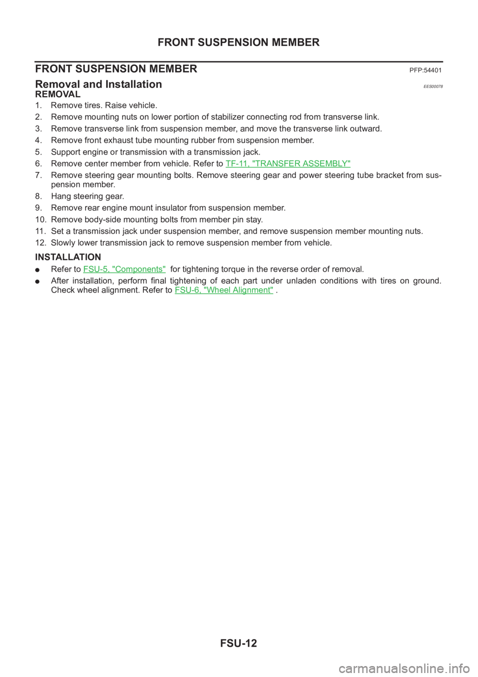
Removal and InstallationEES00078
REMOVAL
1. Remove tires. Raise vehicle.
2. Remove mounting nuts on lower portion of stabilizer connecting rod from transverse link.
3. Remove transverse link from suspension member, and move the transverse link outward.
4. Remove front exhaust tube mounting rubber from suspension member.
5. Support engine or transmission with a transmission jack.
6. Remove center member from vehicle. Refer to TF-11, "
TRANSFER ASSEMBLY"
7. Remove steering gear mounting bolts. Remove steering gear and power steering tube bracket from sus-
pension member.
8. Hang steering gear.
9. Remove rear engine mount insulator from suspension member.
10. Remove body-side mounting bolts from member pin stay.
11. Set a transmission jack under suspension member, and remove suspension member mounting nuts.
12. Slowly lower transmission jack to remove suspension member from vehicle.
INSTALLATION
●Refer to FSU-5, "Components" for tightening torque in the reverse order of removal.
●After installation, perform final tightening of each part under unladen conditions with tires on ground.
Check wheel alignment. Refer to FSU-6, "
Wheel Alignment" .