Page 3700 of 3833
.1. 10A fuse
2. Poor audio unit case groun")
AV-12
AUDIO
Trouble Diagnoses
EKS002F5
AUDIO UNIT
Symptom Possible causes Repair order
Audio unit inoperative (no digital display
and no sound from speakers).1. 10A fuse
2. Poor audio unit case ground
3. Audio unit1. Check 10A fuse [No. 4, located
in fuse block (J/B)]. Turn ignition
switch ON and verify that battery
positive voltage is present at ter-
minal 6 of audio unit.
2. Check audio unit case ground.
3. Remove audio unit for repair.
Audio unit presets are lost when ignition
switch is turned OFF.1. 15A fuse
2. Audio unit1. Check 15A fuse (No. 32, located
in fuse and fusible link box) and
verify that battery positive volt-
age is present at terminal 3 of
audio unit.
2. Remove audio unit for repair.
Individual rear speaker is noisy or inopera-
tive.1. Each speaker
2. Output circuit to each speaker1. Check speaker.
2. Check the output circuits to each
speaker between audio unit and
each speaker.
AM/FM stations are weak or noisy. 1. Roof antenna
2. Audio unit ground
3. Audio unit1. Check roof antenna.
2. Check audio unit ground condi-
tion.
3. Remove audio unit for repair.
Audio unit generates noise in AM and FM
modes with engine running.1. Poor audio unit ground
2. Loose or missing ground bonding straps
3. Ignition condenser or rear window defogger
noise suppressor condenser
4. Ignition coil or secondary wiring
5. Audio unit1. Check audio unit ground.
2. Check ground bonding straps.
3. Replace ignition condenser or
rear window defogger noise sup-
pressor condenser.
4. Check ignition coil and second-
ary wiring.
5. Remove audio unit for repair.
Audio unit generates noise in AM and FM
modes with accessories on (switch pops
and motor noise).1. Poor audio unit ground
2. Antenna
3. Accessory ground
4. Malfunctioning accessory1. Check audio unit ground.
2. Check antenna.
3. Check accessory ground.
4. Replace accessory.
Page 3704 of 3833
AV-16
AUDIO ANTENNA
AUDIO ANTENNA
PFP:28200
Antenna RouteEKS002PW
Removal and Installation of Roof AntennaEKS002PX
1. Remove headlining.
●Refer to EI-29, "HEADLINING" in “Exterior/Interior (EI)” sec-
tion.
2. Remove roof antenna mounting nuts, antenna plug, and power
connector. Then remove roof antenna.
SKIA0894E
SKIA0895E
SKIA0009E
Page 3706 of 3833
PG-2
POWER SUPPLY ROUTING
POWER SUPPLY ROUTING
PFP:00011
Schematic EKS00322
TKWA0730E
SMA for models with roof mounted driving lamp
Page 3707 of 3833
POWER SUPPLY ROUTING
PG-3
C
D
E
F
G
H
I
J
L
MA
B
PG
Wiring Diagram — POWER — EKS00323
BATTERY POWER SUPPLY — IGNITION SW. IN ANY POSITION
TKWA0120E
SMA for models with roof mounted driving lamp
Page 3717 of 3833
GROUND
PG-13
C
D
E
F
G
H
I
J
L
MA
B
PG
GROUND PFP:00011
Ground Distribution EKS0032H
MAIN HARNESS/LHD MODELS
CKWA0043E
SMA for models with roof mounted driving lamp
Page 3719 of 3833
GROUND
PG-15
C
D
E
F
G
H
I
J
L
MA
B
PG
MAIN HARNESS/RHD MODELS
CKWA0045E
SMA for models with roof mounted driving lamp
Page 3722 of 3833
PG-18
GROUND
ENGINE ROOM HARNESS/RHD MODELS
CKWA0048E
SMA for models with roof mounted driving lamp
Page 3736 of 3833
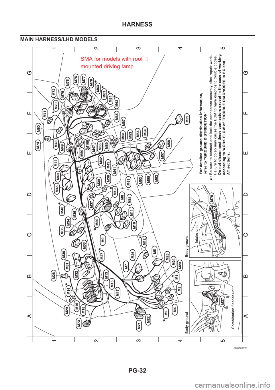
PG-32
HARNESS
MAIN HARNESS/LHD MODELS
CKWA0157E
SMA for models with roof �
mounted driving lamp