Page 1933 of 3833
![NISSAN X-TRAIL 2001 Service Repair Manual FUEL TANK
FL-9
[QR]
C
D
E
F
G
H
I
J
K
L
MA
FL
FUEL TANKPFP:17202
Removal and InstallationEBS00KOW
REMOVAL
WARNING:
Be sure to read “General Precautions” when working on fuel system. Refer to FL-3, NISSAN X-TRAIL 2001 Service Repair Manual FUEL TANK
FL-9
[QR]
C
D
E
F
G
H
I
J
K
L
MA
FL
FUEL TANKPFP:17202
Removal and InstallationEBS00KOW
REMOVAL
WARNING:
Be sure to read “General Precautions” when working on fuel system. Refer to FL-3,](/manual-img/5/57405/w960_57405-1932.png)
FUEL TANK
FL-9
[QR]
C
D
E
F
G
H
I
J
K
L
MA
FL
FUEL TANKPFP:17202
Removal and InstallationEBS00KOW
REMOVAL
WARNING:
Be sure to read “General Precautions” when working on fuel system. Refer to FL-3, "
General Precau-
tions" .
1. Release fuel pressure from fuel line. Refer to EC-775, "
FUEL
PRESSURE RELEASE" [QR20DE (WITH EURO-OBD)], EC-
11 3 9 , "FUEL PRESSURE RELEASE" [QR20DE (WITHOUT
EURO-OBD)], EC-42, "
FUEL PRESSURE RELEASE"
[QR25DE (WITH EURO-OBD)] or EC-452, "FUEL PRESSURE
RELEASE" [QR25DE (WITHOUT EURO-OBD)].
2. Open the fuel filler cap and release the pressure inside the fuel
tank.
3. Remove rear seat bottom.
4. Remove inspection hole cover, harness connector and fuel feed
hose.
5. Drain fuel from fuel tank if necessary. For the draining procedure, refer to Step 4 in removal of FL-4,
"FUEL LEVEL SENSOR UNIT, FUEL FILTER AND FUEL PUMP ASSEMBLY" .
CAUTION:
For the safety work and to maintain fuel tank gravity at center, drain fuel to the level where fuel
tank weight at left and right becomes equal.
6. Disconnect the quick connector.
●Put mating marks on hoses for correct installation.
PBIC0246E
1. Fuel filler cap 2. Grommet 3. Fuel filler tube
4. Vent hose 5. Vent tube 6. Fuel tank
7. Fuel filler hose 8. Fuel tank band 9. Fuel tank protector
KBIA0280E
Page 1935 of 3833
FUEL TANK
FL-11
[QR]
C
D
E
F
G
H
I
J
K
L
MA
FL
INSPECTION AFTER INSTALLATION
Make sure there is no fuel leakage at connections in the following steps.
1. Apply fuel pressure to fuel lines with turning ignition switch ON (with engine stopped). Then check for fuel
leaks at connections.
2. Start the engine and rev it up and check for fuel leaks at connections.
Page 1938 of 3833
![NISSAN X-TRAIL 2001 Service Repair Manual FL-14
[YD22DDTi]
FUEL SYSTEM
FUEL SYSTEM
PFP:17503
Checking Fuel LinesEBS00BKH
Inspect fuel lines, filler cap and tank for improper attachment, leaks,
cracks, damage, loose connections, chafing or det NISSAN X-TRAIL 2001 Service Repair Manual FL-14
[YD22DDTi]
FUEL SYSTEM
FUEL SYSTEM
PFP:17503
Checking Fuel LinesEBS00BKH
Inspect fuel lines, filler cap and tank for improper attachment, leaks,
cracks, damage, loose connections, chafing or det](/manual-img/5/57405/w960_57405-1937.png)
FL-14
[YD22DDTi]
FUEL SYSTEM
FUEL SYSTEM
PFP:17503
Checking Fuel LinesEBS00BKH
Inspect fuel lines, filler cap and tank for improper attachment, leaks,
cracks, damage, loose connections, chafing or deterioration.
If necessary, repair or replace damaged parts.
General PrecautionsEBS00BKI
WARNING:
When replacing fuel line parts, be sure to observe the following.
●Put a “CAUTION: INFLAMMABLE” sign in workshop.
●Be sure to work in a well-ventilated area and furnish workshop with a CO2 fire extinguisher.
●Do not smoke while servicing fuel system. Keep open flames and spark away from work area.
CAUTION:
●Before removing fuel line parts, carry out the following procedures:
–a) Put drained fuel in an explosion-proof container and put the lid on securely. Keep the container
in safe area.
–b) Disconnect battery ground cable.
●Always replace O-ring and clamps with new ones.
●Do not kink or twist tubes when they are being installed.
●Do not tighten hose clamps excessively to avoid damaging hoses.
●After installing tubes, make sure there is no fuel leakage at connections in the following steps.
–a) Apply fuel pressure to fuel lines with turning ignition switch “ON” (with engine stopped). Then
check for fuel leaks at connections.
–b) Start the engine and rev it up and check for fuel leaks at connections.
SMA803A
Page 1939 of 3833
![NISSAN X-TRAIL 2001 Service Repair Manual FUEL FILTER
FL-15
[YD22DDTi]
C
D
E
F
G
H
I
J
K
L
MA
FL
FUEL FILTERPFP:16400
Removal and InstallationEBS00BLA
REMOVAL
1. Remove air duct and upper air cleaner case.
2. Remove fuel filter protector.
3. NISSAN X-TRAIL 2001 Service Repair Manual FUEL FILTER
FL-15
[YD22DDTi]
C
D
E
F
G
H
I
J
K
L
MA
FL
FUEL FILTERPFP:16400
Removal and InstallationEBS00BLA
REMOVAL
1. Remove air duct and upper air cleaner case.
2. Remove fuel filter protector.
3.](/manual-img/5/57405/w960_57405-1938.png)
FUEL FILTER
FL-15
[YD22DDTi]
C
D
E
F
G
H
I
J
K
L
MA
FL
FUEL FILTERPFP:16400
Removal and InstallationEBS00BLA
REMOVAL
1. Remove air duct and upper air cleaner case.
2. Remove fuel filter protector.
3. Disconnect fuel hoses at fuel filter bracket.
CAUTION:
Plug the pipe to prevent fuel from draining.
4. Remove fuel filter with bracket.
CAUTION:
Do not splash fuel during removal. If fuel is splashed,
immediately wipe it off.
5. Using band-type filter wrench (commercial service tool), remove
fuel filter.
6. Turn fuel filter upside down to drain fuel.
7. Remove drain plug from fuel filter.
INSTALLATION
Install in reverse order of removal, paying attention to following:
●Replace O-ring on drain plug with new one.
●Screw the fuel filter by hand until packing contacts sealing surface of bracket. Then tighten it by turning
approximately 2/3 turn.
●After installation, bleed air from fuel path. Refer to FL-16, "Air Bleeding" .
INSPECTION AFTER INSTALLATION
Make sure there is no fuel leakage at connections in the following steps.
1. Apply fuel pressure to fuel lines with turning ignition switch “ON” (with engine stopped). Then check for
fuel leaks at connections.
2. Start the engine and rev it up and check for fuel leaks at connections.
SBIA0134E
SBIA0135E
SBIA0136E
Drain plug
: 3.9 - 5.9 N·m (0.4 - 0.6 kg-m, 35 - 52 in-lb)
Page 1944 of 3833
FL-20
[YD22DDTi]
FUEL LEVEL SENSOR UNIT
●Visually confirm that the two retainer tabs are connected to the connector.
●Pull the tube and the connector to make sure they are securely connected.
●Install fuel level sensor unit with mating mark (triangular protrusion) facing between two carved lines on
fuel tank. (Figure shows left side of fuel tank.)
NOTE:
On right side of fuel tank, there are three carved lines on fuel tank. Set mating mark between two outer
carved lines.
●Install the inspection hole cover with the front mark (arrow)
facing front of the vehicle (Both for RH and LH).
INSPECTION AFTER INSTALLATION
Make sure there is no fuel leakage at connections in the following steps.
1. Apply fuel pressure to fuel lines with turning ignition switch ON (with engine stopped). Then check for fuel
leaks at connections.
2. Start the engine and rev it up and check for fuel leaks at connections.
SBIA0144E
Page 1947 of 3833
FUEL TANK
FL-23
[YD22DDTi]
C
D
E
F
G
H
I
J
K
L
MA
FL
1. Apply fuel pressure to fuel lines with turning ignition switch “ON” (with engine stopped). Then check for
fuel leaks at connections.
2. Start the engine and rev it up and check for fuel leaks at connections.
Page 1962 of 3833

CL-4
NOISE, VIBRATION, AND HARSHNESS (NVH) TROUBLESHOOTING
NOISE, VIBRATION, AND HARSHNESS (NVH) TROUBLESHOOTING
PFP:00003
NVH Troubleshooting ChartECS008B8
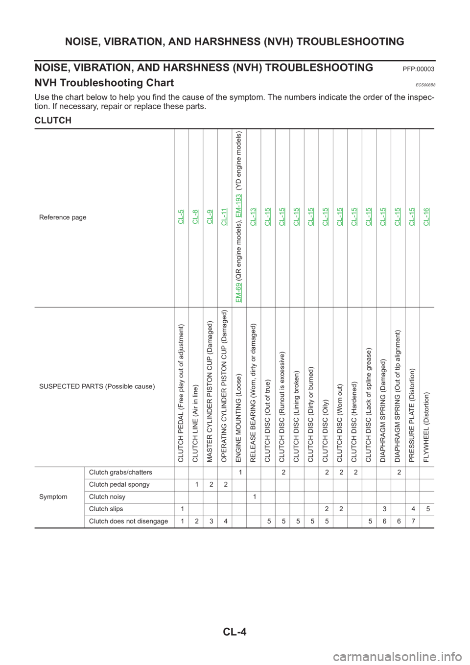
Use the chart below to help you find the cause of the symptom. The numbers indicate the order of the inspec-
tion. If necessary, repair or replace these parts.
CLUTCH
Reference pageCL-5CL-8CL-9CL-11
EM-69
(QR engine models), EM-193
(YD engine models)
CL-13
CL-15CL-15CL-15CL-15CL-15CL-15CL-15CL-15CL-15CL-15CL-15CL-16
SUSPECTED PARTS (Possible cause)
CLUTCH PEDAL (Free play out of adjustment)
CLUTCH LINE (Air in line)
MASTER CYLINDER PISTON CUP (Damaged)
OPERATING CYLINDER PISTON CUP (Damaged)
ENGINE MOUNTING (Loose)
RELEASE BEARING (Worn, dirty or damaged)
CLUTCH DISC (Out of true)
CLUTCH DISC (Runout is excessive)
CLUTCH DISC (Lining broken)
CLUTCH DISC (Dirty or burned)
CLUTCH DISC (Oily)
CLUTCH DISC (Worn out)
CLUTCH DISC (Hardened)
CLUTCH DISC (Lack of spline grease)
DIAPHRAGM SPRING (Damaged)
DIAPHRAGM SPRING (Out of tip alignment)
PRESSURE PLATE (Distortion)
FLYWHEEL (Distortion)
SymptomClutch grabs/chatters 1 2 2 2 2 2
Clutch pedal spongy 1 2 2
Clutch noisy 1
Clutch slips 1 2 2 3 4 5
Clutch does not disengage 1 2 3 4 5 5 5 5 5 5 6 6 7
Page 1974 of 3833

CL-16
CLUTCH DISC, CLUTCH COVER AND FLYWHEEL
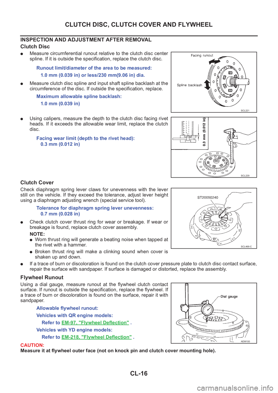
INSPECTION AND ADJUSTMENT AFTER REMOVAL
Clutch Disc
●Measure circumferential runout relative to the clutch disc center
spline. If it is outside the specification, replace the clutch disc.
●Measure clutch disc spline and input shaft spline backlash at the
circumference of the disc. If outside the specification, replace.
●Using calipers, measure the depth to the clutch disc facing rivet
heads. If it exceeds the allowable wear limit, replace the clutch
disc.
Clutch Cover
Check diaphragm spring lever claws for unevenness with the lever
still on the vehicle. If they exceed the tolerance, adjust lever height
using a diaphragm adjusting wrench (special service tool).
●Check clutch cover thrust ring for wear or breakage. If wear or
breakage is found, replace clutch cover assembly.
NOTE:
●Worn thrust ring will generate a beating noise when tapped at
the rivet with a hammer.
●Broken thrust ring will make a clinking sound when cover is
shaken up and down.
●If a trace of burn or discoloration is found on the clutch cover pressure plate to clutch disc contact surface,
repair the surface with sandpaper. If surface is damaged or distorted, replace the assembly.
Flywheel Runout
Using a dial gauge, measure runout at the flywheel clutch contact
surface. If runout is outside the specification, replace the flywheel. If
a trace of burn or discoloration is found on the surface, repair it with
sandpaper.
CAUTION:
Measure it at flywheel outer face (not on knock pin and clutch cover mounting hole). Runout limit/diameter of the area to be measured:
1.0 mm (0.039 in) or less/230 mm(9.06 in) dia.
Maximum allowable spline backlash:
1.0 mm (0.039 in)
SCL221
Facing wear limit (depth to the rivet head):
0.3 mm (0.012 in)
SCL229
Tolerance for diaphragm spring lever unevenness:
0.7 mm (0.028 in)
SCL466-C
Allowable flywheel runout:
Vehicles with QR engine models:
Refer to EM-97, "
Flywheel Deflection" .
Vehicles with YD engine models:
Refer to EM-218, "
Flywheel Deflection" .AEM100