2001 NISSAN X-TRAIL wheel torque
[x] Cancel search: wheel torquePage 2844 of 3833
![NISSAN X-TRAIL 2001 Service Repair Manual BRC-60
[ESP/TCS/ABS]
GENERAL INFORMATION
●When starting the engine, or just after starting the vehicle, the brake pedal may vibrate or the
motor operating noise may be heard from the engin](/manual-img/5/57405/w960_57405-2843.png "NISSAN X-TRAIL 2001 Service Repair Manual BRC-60
[ESP/TCS/ABS]
GENERAL INFORMATION
●When starting the engine, or just after starting the vehicle, the brake pedal may vibrate or the
motor operating noise may be heard from the engin")
BRC-60
[ESP/TCS/ABS]
GENERAL INFORMATION
●When starting the engine, or just after starting the vehicle, the brake pedal may vibrate or the
motor operating noise may be heard from the engine compartment. This is a normal status of the
operation check.
●The stopping distance may be longer than that of vehicles without ABS when the vehicle drives on
rough, gravel, or snowy (fresh deep snow) road.
TCS FunctionsEFS0019V
1. With the wheel sensor signals from 4 wheels, the ESP/TCS/ABS control unit detects a wheel spin. If a
wheel spins, the control unit controls brake fluid pressure to the spinning wheel, and cuts the fuel to the
engine. It also closes the throttle valve to reduce the engine torque. Furthermore, throttle position is con-
trolled to the appropriate engine torque.
2. If a wheel spins, the TCS system works and function by applying brake fluid pressure to the spinning
wheel.
3. During TCS operation, it informs a driver of system operation by flashing SLIP indicator lamp.
CAUTION:
●During TCS operation, the body and the brake pedal lightly vibrate and the mechanical noise may
be heard. This is a normal condition.
●Depending on road circumstances, the driver may have a sluggish feel. This is not abnormal,
because the optimum traction has the highest priority by TCS operation.
●When the vehicle is passing through a road where the surface friction coefficient varies, down-
shifting or depressing the accelerator pedal fully may activate TCS temporarily.
ESP FunctionsEFS0019W
1. The Electronic Stability Program is called the ESP for short.
The ESP is indicated as the VDC (the Vehicle Dynamics Control) on the CONSULT-II screen.
2. In addition to the ABS/TCS function, ESP detects the driver's steering operation amount and brake opera-
tion amount from the steering wheel angle sensor and pressure sensor. Using the information from the
yaw rate and side G sensor and wheel sensors, ESP judges the driving condition (conditions of under-
steer and oversteer) to improve the stability by controlling the brake on 4 wheels and engine output.
3. During ESP operation, the SLIP indicator lamp flashes to inform the driver of the operation.
CAUTION:
●During ESP operation, the body and the brake pedal lightly vibrate and their mechanical noise
may be heard. This is a normal condition.
●If the vehicle is rotated on a turn table, or rolled and rocked on a ship, the ABS warning lamp,
ESP OFF indicator lamp, and SLIP indicator lamp may turn ON. In this case, start the engine on a
normal road again. If the ABS warning lamp, ESP OFF indicator lamp, and SLIP indicator lamp
turn OFF after the restart, it is normal.
●When driving in a steep slope such as a bank, the ABS warning lamp, ESP OFF indicator lamp,
and SLIP indicator lamp may turn ON. In this case, start the engine on a normal road again. If the
ABS warning lamp, ESP OFF indicator lamp, and SLIP indicator lamp turn OFF after the restart, it
is normal.
Page 2875 of 3833
![NISSAN X-TRAIL 2001 Service Repair Manual TROUBLE DIAGNOSIS
BRC-91
[ESP/TCS/ABS]
C
D
E
G
H
I
J
K
L
MA
B
BRC
ABS Warning Lamp, ESP OFF Indicator Lamp, SLIP Indicator Lamp ON/OFF Timing
×:ON –: Lamp OFF
×: Applicable
–: Not applicable
Ba](/manual-img/5/57405/w960_57405-2874.png "NISSAN X-TRAIL 2001 Service Repair Manual TROUBLE DIAGNOSIS
BRC-91
[ESP/TCS/ABS]
C
D
E
G
H
I
J
K
L
MA
B
BRC
ABS Warning Lamp, ESP OFF Indicator Lamp, SLIP Indicator Lamp ON/OFF Timing
×:ON –: Lamp OFF
×: Applicable
–: Not applicable
Ba")
TROUBLE DIAGNOSIS
BRC-91
[ESP/TCS/ABS]
C
D
E
G
H
I
J
K
L
MA
B
BRC
ABS Warning Lamp, ESP OFF Indicator Lamp, SLIP Indicator Lamp ON/OFF Timing
×:ON –: Lamp OFF
×: Applicable
–: Not applicable
Basic InspectionEFS001A9
PRELIMINARY CHECK 1: (BRAKE FLUID LEVEL AND LEAK INSPECTION)
1. Check the fluid level in the brake reservoir tank. If the fluid level is low, refill the brake fluid.
2. Check the area around the brake piping, ESP actuator for leaks. If a leak or oozing is detected, check as
follows:
●If the connections at the ESP actuator are loose, tighten the piping to the specified torque. Then check
again for leaks, and make sure that there is no fluid leak.
●If the flare nuts at the connections and the threads of the ESP actuator are damaged, replace the dam-
aged parts. Then check again for leaks, and make sure that there is no fluid leak.
●If a leak or oozing is detected on other parts than the ESP actuator connections, wipe the applicable
part with a clean cloth. Then check again for leaks, and if there is still a leak or oozing, replace the dam-
aged part.
ESP/TCS operation
(SLIP lamp ON)When the vehicle is passing through a road where the surface friction
coefficient varies or the wheel speed changes suddenly by downshifting
or depressing of the accelerator pedal fully, TCS may be activated tem-
porarily.
Normal
Cancel the ESP/TCS
function for the
inspection on a chas-
sis dynamometer. Before the speedometer inspection, turn ESP OFF switch off to cancel
the ESP/TCS function.
When the accelerator pedal is depressed on a chassis dynamometer,
the vehicle speed will not increase. This is not malfunction, because
TCS is activated by the wheel speed difference between front and rear.
The warning lamp may also illuminate to show “sensor system failure” in
this case. This is not malfunction either, because the stationary front
wheels are detected. Restart the engine, and drive the vehicle at 30 km/
h or higher to check that the warning lamp no longer illuminates.
ABS operation (Longer stop-
ping distance)The stopping distance may be longer for the vehicles with ABS when the
vehicle is driver on snowy and rough road. When driving on the road like
that, slow down the speed.Normal
Sluggish feelDepending on road circumstances, the driver may have a sluggish feel.
This is not abnormal, because the optimum traction has the highest pri-
ority (safety first) by TCS operation. Sometimes the driver has a slight
sluggish feel against the substantial accelerator pedal operation.Normal Symptom Symptom description Result
Condition ABS warning lampESP OFF
indicator lampSLIP indicator lamp Remarks
When the ignition switch is
OFF––– —
After the ignition switch is
turned ON
For Approx. 0.5 seconds×××—
Ignition switch ON
Approx. 0.5 seconds later––– —
When the ESP OFF switch
turns ON (ESP/TCS function
OFF).–×–Lamp goes off after Approx. 2
seconds when the engine re-start.
ESP/TCS/ABS
malfunction×××—
××–When the ESP/TCS/ABS control
unit is abnormal (power supply or
ground malfunction).
When the ESP/TCS ism
abnormal.–××—
Page 2876 of 3833
![NISSAN X-TRAIL 2001 Service Repair Manual BRC-92
[ESP/TCS/ABS]
TROUBLE DIAGNOSIS
●If a leak or oozing is detected on the ESP actuator body, wipe the applicable part with a clean cloth.
Then check again for leaks, and if th](/manual-img/5/57405/w960_57405-2875.png "NISSAN X-TRAIL 2001 Service Repair Manual BRC-92
[ESP/TCS/ABS]
TROUBLE DIAGNOSIS
●If a leak or oozing is detected on the ESP actuator body, wipe the applicable part with a clean cloth.
Then check again for leaks, and if th")
BRC-92
[ESP/TCS/ABS]
TROUBLE DIAGNOSIS
●If a leak or oozing is detected on the ESP actuator body, wipe the applicable part with a clean cloth.
Then check again for leaks, and if there is still a leak or oozing, replace the ESP actuator body.
CAUTION:
Do not disassemble the actuator body.
3. Check the brake disc rotor and pads.
PRELIMINARY CHECK 2: (INSPECTION FOR LOOSE POWER SUPPLY TERMINAL)
Check the battery for looseness on the battery positive/negative terminals and ground connection. If loose-
ness is detected, tighten the piping to the specified torque. Check that the battery voltage does not drop and
the alternator is normal.
PRELIMINARY CHECK 3: (INSPECTION FOR ABS WARNING LAMP, ESP OFF INDICATOR
LAMP, AND SLIP INDICATOR LAMP)
1. Check that the ABS warning lamp is ON for Approx. 0.5 seconds when the ignition switch is turned ON. If
it does not turn on, check the ABS warning lamp and the circuit, and the combination meter.
2. Check that ESP OFF indicator lamp is ON for Approx. 0.5 seconds when the ignition switch is turned ON.
If it does not turn ON, check the ESP OFF indicator lamp and the circuit, and the combination meter.
3. Check that the SLIP indicator lamp is ON for Approx. 0.5 seconds when the ignition switch is turned ON. If
it does not turn ON, check the SLIP indicator lamp and the circuit.
4. With the engine running, check the ESP OFF indicator lamp turns ON and OFF when the ESP OFF
switch turns ON and OFF. If it dose not operate in accordance with the switch, check the ESP OFF switch
and the circuit.
5. Check that the ESP OFF indicator lamp turns OFF after Approx. 2 seconds delay when the ESP OFF
switch turned ON (The ESP/TCS system was not operated). If the ESP OFF indicator lamp does not turn
OFF in 10 seconds from the engine start, perform the self-diagnosis of ESP/TCS/ABS control unit.
Inspection 1 Wheel Sensor and CircuitEFS001AB
Inspection procedure
1. SELF-DIAGNOSIS RESULT CHECK 1
Check the self-diagnosis results.
Are any self-diagnosis result items above indicated?
>> GO TO 2.
2. CHECK THE CONNECTOR
Remove connectors of the wheel sensor which is malfunctioning and the ESP/TCS/ABS control unit. Check
whether the deformation of terminal, or incorporate connection of connectors. Then, connect connectors. In
addition, check if the wheel sensor cable is damaged due to friction.
Does ABS warning lamp is out when driving 30 km/h (19 MPH) for Approx. One minute?
YES >> Check is completed.
NO >> GO TO 3.
Self-diagnosis results
CONSULT-II indication item
ABS SENSOR [ABNORMAL SIGNAL]
FR RH SENSOR – 1
FR RH SENSOR – 2
FR LH SENSOR – 1
FR LH SENSOR – 2
RR RH SENSOR – 1
RR RH SENSOR – 2
RR LH SENSOR – 1
RR LH SENSOR – 2
Page 2905 of 3833
![NISSAN X-TRAIL 2001 Service Repair Manual WHEEL SPEED SENSORS
BRC-121
[ESP/TCS/ABS]
C
D
E
G
H
I
J
K
L
MA
B
BRC
WHEEL SPEED SENSORSPFP:47910
Removal and InstallationEFS001CD
CAUTION:
●Be careful not to damage sensor edge and rotor t](/manual-img/5/57405/w960_57405-2904.png "NISSAN X-TRAIL 2001 Service Repair Manual WHEEL SPEED SENSORS
BRC-121
[ESP/TCS/ABS]
C
D
E
G
H
I
J
K
L
MA
B
BRC
WHEEL SPEED SENSORSPFP:47910
Removal and InstallationEFS001CD
CAUTION:
●Be careful not to damage sensor edge and rotor t")
WHEEL SPEED SENSORS
BRC-121
[ESP/TCS/ABS]
C
D
E
G
H
I
J
K
L
MA
B
BRC
WHEEL SPEED SENSORSPFP:47910
Removal and InstallationEFS001CD
CAUTION:
●Be careful not to damage sensor edge and rotor tooth. Before removing front or rear wheel hub,
remove wheel sensor to avoid sensor wiring damage. Otherwise, sensor may be deactivated.
●When removing sensor, avoid rotating it as much as possible. Do not forcibly pull sensor harness.
●When installing, check sensor pick-up and mounting hole for foreign material such as iron chips.
Check no foreign material has been caught in sensor rotor. Remove any foreign material found.
Tighten mounting bolts and nuts to the specified torque.
SFIA0926E
Page 2911 of 3833
PS-1
POWER STEERING SYSTEM
G STEERING
CONTENTS
C
D
E
F
H
I
J
K
L
M
SECTION
A
B
PS
POWER STEERING SYSTEM
PRECAUTIONS .......................................................... 2
Precautions for Supplemental Restraint System
(SRS) “AIR BAG” and “SEAT BELT PRE-TEN-
SIONER” .................................................................. 2
Caution ..................................................................... 2
PREPARATION ........................................................... 3
Special Service Tools ............................................... 3
NOISE, VIBRATION, AND HARSHNESS (NVH)
TROUBLESHOOTING ................................................ 4
NVH Trouble shooting Chart .................................... 4
POWER STEERING FLUID ........................................ 5
Checking Fluid Level ........................................... ..... 5
Checking Fluid Leak ............................................ ..... 5
Bleeding Hydraulic System ...................................... 5
STEERING WHEEL .................................................... 6
On-Vehicle Inspection and Service .......................... 6
PLAY INSPECTION .............................................. 6
NEUTRAL POSITION INSPECTION .................... 6
STEERING TORQUE CHECK .............................. 6
STEERING ANGLE INSPECTION ........................ 6
Removal and Installation .......................................... 7
REMOVAL ............................................................. 7
INSTALLATION ..................................................... 7
STEERING COLUMN ................................................. 9
Removal and Installation .......................................... 9
REMOVAL OF LOWER JOINT AND HOLE
COVER ................................................................. 9
INSTALLATION OF LOWER JOINT AND HOLE
COVER ................................................................. 9
REMOVAL OF STEERING COLUMN ASSEM-
BLY ...................................................................... 10
INSTALLING STEERING COLUMN ASSEMBLY ... 10
Disassembly and Assembly .................................... 11
DISASSEMBLY .................................................... 11
INSPECTION AFTER DISASSEMBLY. ............... 11
ASSEMBLY .......................................................... 11
POWER STEERING GEAR AND LINKAGE ............ 12
Removal and Installation ........................................ 12
REMOVAL ........................................................... 12INSTALLATION ................................................... 12
Components ........................................................... 14
MODEL PR24AD ................................................. 14
Disassembly and Assembly .................................... 15
DISASSEMBLY ................................................... 15
INSPECTION AFTER DISASSEMBLY ................ 16
ASSEMBLY ......................................................... 17
POWER STEERING OIL PUMP ............................... 24
On-Vehicle Inspection and Service ......................... 24
OIL PUMP PULLEY HYDRAULIC PRESSURE
INSPECTION ...................................................... 24
Removal and Installation (QR20DE and QR25DE
engine models) ....................................................... 24
REMOVAL ........................................................... 24
INSTALLATION ................................................... 24
Disassembly and Assembly(QR20DE and
QR25DE engine models) ........................................ 25
INSPECTION BEFORE DISASSEMBLY ............. 25
DISASSEMBLY ................................................... 25
INSPECTION AFTER DISASSEMBLY ................ 26
ASSEMBLY ......................................................... 26
Removal and Installation (YD22DDTi engine
model) ..................................................................... 29
Disassembly and Assembly (YD22DDTi engine
model) ..................................................................... 30
INSPECTION BEFORE DISASSEMBLY ............. 30
DISASSEMBLY ................................................... 31
INSPECTION AFTER DISASSEMBLY ................ 32
ASSEMBLY ......................................................... 32
HYDRAULIC LINE .................................................
... 34
Removal and Installation ........................................ 34
SERVICE DATA AND SPECIFICATIONS (SDS) ...... 36
Wheel ..................................................................... 36
Steering Angle ........................................................ 36
Steering Column ..................................................... 36
Steering Linkage ..................................................... 36
Steering Gear ......................................................... 37
Oil Pump ................................................................. 37
Steering Fluid .......................................................... 37
Page 2913 of 3833
PREPARATION
PS-3
C
D
E
F
H
I
J
K
L
MA
B
PS
PREPARATIONPFP:00002
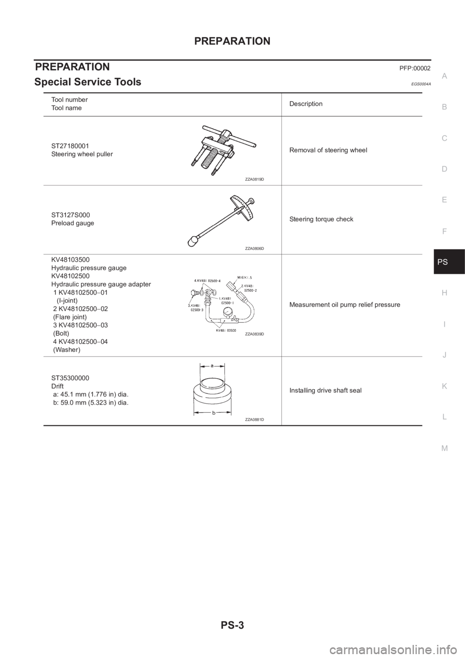
Special Service ToolsEGS0004A
Tool number
Tool nameDescription
ST27180001
Steering wheel pullerRemoval of steering wheel
ST3127S000
Preload gaugeSteering torque check
KV48103500
Hydraulic pressure gauge
KV48102500
Hydraulic pressure gauge adapter
1 KV48102500−01
(I-joint)
2 KV48102500−02
(Flare joint)
3 KV48102500−03
(Bolt)
4 KV48102500−04
(Washer)Measurement oil pump relief pressure
ST35300000
Drift
a: 45.1 mm (1.776 in) dia.
b: 59.0 mm (5.323 in) dia.Installing drive shaft seal
ZZA0819D
ZZA0806D
ZZA0839D
ZZA0881D
Page 2914 of 3833

PS-4
NOISE, VIBRATION, AND HARSHNESS (NVH) TROUBLESHOOTING
NOISE, VIBRATION, AND HARSHNESS (NVH) TROUBLESHOOTING
PFP:00003
NVH Trouble shooting ChartEGS000A9
Use the chart below to help you find the cause of the symptom. If necessary, repair or replace these parts.
×: ApplicableReference page
PS-5PS-5PS-16PS-16PS-16PS-5PS-6–
EM-12
.
–
PS-11
–
PS-9PS-9PS-12
NVH in PR section
NVH in RFD section
NVH in FAX, RAX, FSU, RSU section
NVH in WT section
NVH in WT section
NVH in RAX section
NVH in BR section
Possible cause and SUSPECTED PARTS
Fluid level
Air in hydraulic system
Tie-rod ball joint swinging force
Tie-rod ball joint rotating torque
Tie-rod ball joint end play
Steering gear fluid leakage
Steering wheel play
Steering gear rack sliding force
Drive belt looseness
Improper steering wheel
Improper installation or looseness or tilt lock lever
Mounting rubber deterioration
Steering column deformation or damage
Improper installation or looseness of steering column
Steering linkage looseness
PROPELLER SHAFT
DIFFERENTIAL
AXLE AND SUSPENSION
TIRES
ROAD WHEEL
DRIVE SHAFT
BRAKES
Symptom STEERINGNoise× × ××××× × × ×××××× ×
Shake××× × ×××× ×
Vibration××××× × ×× ×
Shimmy××× × ××× ×
Judder× × ××× ×
Page 2916 of 3833
PS-6
STEERING WHEEL
STEERING WHEEL
PFP:48430
On-Vehicle Inspection and ServiceEGS0004E
PLAY INSPECTION
1. Turn steering wheel to straight-ahead position. Start engine and lightly turn steering wheel clockwise and
counter clockwise until front wheels start moving. Measure travel to starting point on circumference of
steering wheel.
2. If play is outside specifications, check following parts for proper installation: steering gear assembly, front
suspension, axles, and steering column
●Check steering wheel for vertical, horizontal, or axial play.
●Lift vehicle and check steering gear mounting bolts and nuts for looseness.
NEUTRAL POSITION INSPECTION
●After the wheel alignment inspection, carry out the neutral position inspection. Refer to FSU-6, "Wheel
Alignment" .
●Before removing steering wheel, check steering gear neutral position.
1. Set vehicle to straight-ahead position, and check that steering wheel is in neutral position.
2. If it is not in neutral position, remove steering wheel, and install again in properly.
3. If it is not adjusted within two teeth from center of gear, loosen tie rod lock nut. Then turn it to opposite
direction to adjust until amount of left and right becomes equal.
STEERING TORQUE CHECK
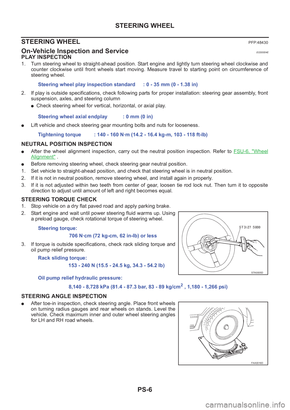
1. Stop vehicle on a dry flat paved road and apply parking brake.
2. Start engine and wait until power steering fluid warms up. Using
a preload gauge, check rotational torque of steering wheel.
3. If torque is outside specifications, check rack sliding torque and
oil pump relief pressure.
STEERING ANGLE INSPECTION
●After toe-in inspection, check steering angle. Place front wheels
on turning radius gauges and rear wheels on stands. Level the
vehicle. Check maximum inner and outer wheel steering angles
for LH and RH road wheels.Steering wheel play inspection standard : 0 - 35 mm (0 - 1.38 in)
Steering wheel axial endplay : 0 mm (0 in)
Tightening torque : 140 - 160 N·m (14.2 - 16.4 kg-m, 103 - 118 ft-lb)
Steering torque:
706 N·cm (72 kg-cm, 62 in-lb) or less
Rack sliding torque:
153 - 240 N (15.5 - 24.5 kg, 34.3 - 54.2 lb)
Oil pump relief hydraulic pressure:
8,140 - 8,728 kPa (81.4 - 87.3 bar, 83 - 89 kg/cm
2 , 1,180 - 1,266 psi)
STA0005D
FAA0016D