2001 NISSAN X-TRAIL oil
[x] Cancel search: oilPage 1918 of 3833
![NISSAN X-TRAIL 2001 Service Repair Manual EC-1568
[YD]
POWER STEERING OIL PRESSURE SWITCH
POWER STEERING OIL PRESSURE SWITCH
PFP:49761
Component DescriptionEBS003PS
The power steering oil pressure switch is attached to the power
ste NISSAN X-TRAIL 2001 Service Repair Manual EC-1568
[YD]
POWER STEERING OIL PRESSURE SWITCH
POWER STEERING OIL PRESSURE SWITCH
PFP:49761
Component DescriptionEBS003PS
The power steering oil pressure switch is attached to the power
ste](/manual-img/5/57405/w960_57405-1917.png)
EC-1568
[YD]
POWER STEERING OIL PRESSURE SWITCH
POWER STEERING OIL PRESSURE SWITCH
PFP:49761
Component DescriptionEBS003PS
The power steering oil pressure switch is attached to the power
steering high-pressure tube and detects a power steering load.
When a power steering load is detected, it signals the ECM. The
ECM adjusts the fuel injector pulse width to increase the idle speed
and adjust for the increased load.
CONSULT-II Reference Value in Data Monitor ModeEBS003PT
Specification data are reference values.
ECM Terminals and Reference ValueEBS003PZ
Specification data are reference values, and are measured between each terminal and ground.
CAUTION:
Do not use ECM ground terminals when measuring input/output voltage. Doing so may result in dam-
age to the ECM's transistor. Use a ground other than ECM terminals, such as the ground.
PBIB0375E
MONITOR ITEM CONDITION SPECIFICATION
PW/ST SIGNAL
●Engine: After warming up, idle the
engineSteering wheel is in neutral position.
(Forward direction)OFF
Steering wheel is turned. ON
TER-
MINAL
NO.WIRE
COLORITEM CONDITION DATA (DC Voltage)
E12 P/BPower steering oil pressure
switch[Engine is running]
●Steering wheel is being turnedApproximately 0V
[Engine is running]
●Steering wheel is not being turnedBATTERY VOLTAGE
(11 - 14V)
Page 1919 of 3833
![NISSAN X-TRAIL 2001 Service Repair Manual POWER STEERING OIL PRESSURE SWITCH
EC-1569
[YD]
C
D
E
F
G
H
I
J
K
L
MA
EC
Wiring DiagramEBS003PU
TBWA0115E NISSAN X-TRAIL 2001 Service Repair Manual POWER STEERING OIL PRESSURE SWITCH
EC-1569
[YD]
C
D
E
F
G
H
I
J
K
L
MA
EC
Wiring DiagramEBS003PU
TBWA0115E](/manual-img/5/57405/w960_57405-1918.png)
POWER STEERING OIL PRESSURE SWITCH
EC-1569
[YD]
C
D
E
F
G
H
I
J
K
L
MA
EC
Wiring DiagramEBS003PU
TBWA0115E
Page 1920 of 3833
![NISSAN X-TRAIL 2001 Service Repair Manual EC-1570
[YD]
POWER STEERING OIL PRESSURE SWITCH
Diagnostic Procedure
EBS003PV
1. CHECK OVERALL FUNCTION
With CONSULT-II
1. Start engine.
2. Check “PW/ST SIGNAL” in “DATA MONITOR” mode with CON NISSAN X-TRAIL 2001 Service Repair Manual EC-1570
[YD]
POWER STEERING OIL PRESSURE SWITCH
Diagnostic Procedure
EBS003PV
1. CHECK OVERALL FUNCTION
With CONSULT-II
1. Start engine.
2. Check “PW/ST SIGNAL” in “DATA MONITOR” mode with CON](/manual-img/5/57405/w960_57405-1919.png)
EC-1570
[YD]
POWER STEERING OIL PRESSURE SWITCH
Diagnostic Procedure
EBS003PV
1. CHECK OVERALL FUNCTION
With CONSULT-II
1. Start engine.
2. Check “PW/ST SIGNAL” in “DATA MONITOR” mode with CON-
SULT-II under the following conditions.
OK or NG
OK >>INSPECTION END
NG >> GO TO 2.
2. CHECK POWER STEERING OIL PRESSURE SWITCH GROUND CIRCUIT FOR OPEN AND SHORT
1. Turn ignition switch “OFF”.
2. Disconnect power steering oil pressure switch harness connec-
tor.
3. Check harness continuity between power steering oil pressure
switch terminal 2 and engine ground. Refer to Wiring Diagram.
4. Also check harness for short to power.
OK or NG
OK >> GO TO 3.
NG >> Repair open circuit or short to power in harness or con-
nectors.
3. CHECK POWER STEERING OIL PRESSURE SWITCH INPUT SIGNAL CIRCUIT FOR OPEN AND
SHORT
1. Disconnect ECM harness connector.
2. Check harness continuity between ECM terminal E12 and power steering oil pressure switch terminal 1.
Refer to Wiring Diagram.
3. Also check harness for short to ground and short to power.
OK or NG
OK >> GO TO 4.
NG >> Repair open circuit or short to ground or short to power in harness or connectors.
4. CHECK POWER STEERING OIL PRESSURE SWITCH
Refer to EC-1571, "
Component Inspection" .
OK or NG
OK >> GO TO 5.
NG >> Replace power steering oil pressure switch.
Conditions PW/ST SIGNAL
Steering in neutral position OFF
Steering is turned ON
PBIB0434E
Continuity should exist.
PBIB0375E
Continuity should exist.
Page 1921 of 3833
![NISSAN X-TRAIL 2001 Service Repair Manual POWER STEERING OIL PRESSURE SWITCH
EC-1571
[YD]
C
D
E
F
G
H
I
J
K
L
MA
EC
5.CHECK INTERMITTENT INCIDENT
Refer to EC-1441, "
TROUBLE DIAGNOSIS FOR INTERMITTENT INCIDENT" .
>>INSPECTION END
Comp NISSAN X-TRAIL 2001 Service Repair Manual POWER STEERING OIL PRESSURE SWITCH
EC-1571
[YD]
C
D
E
F
G
H
I
J
K
L
MA
EC
5.CHECK INTERMITTENT INCIDENT
Refer to EC-1441, "
TROUBLE DIAGNOSIS FOR INTERMITTENT INCIDENT" .
>>INSPECTION END
Comp](/manual-img/5/57405/w960_57405-1920.png)
POWER STEERING OIL PRESSURE SWITCH
EC-1571
[YD]
C
D
E
F
G
H
I
J
K
L
MA
EC
5.CHECK INTERMITTENT INCIDENT
Refer to EC-1441, "
TROUBLE DIAGNOSIS FOR INTERMITTENT INCIDENT" .
>>INSPECTION END
Component InspectionEBS003PW
POWER STEERING OIL PRESSURE SWITCH
1. Disconnect power steering oil pressure switch harness connector and then start engine.
2. Check continuity between power steering oil pressure switch ter-
minal 1 and 2 under the following conditions.
Removal and InstallationEBS008ZH
POWER STEERING OIL PRESSURE SWITCH
Refer to PS-34, "HYDRAULIC LINE" .
Conditions Continuity
Steering wheel is being fully turned. Yes
Steering wheel is not being turned. No
PBIB0435E
Page 1932 of 3833
![NISSAN X-TRAIL 2001 Service Repair Manual FL-8
[QR]
FUEL LEVEL SENSOR UNIT, FUEL FILTER AND FUEL PUMP ASSEMBLY
3. Separate the fuel filter and fuel level sensor unit.
a. Fit a used O-ring into space between fuel level sensor unit and
fuel NISSAN X-TRAIL 2001 Service Repair Manual FL-8
[QR]
FUEL LEVEL SENSOR UNIT, FUEL FILTER AND FUEL PUMP ASSEMBLY
3. Separate the fuel filter and fuel level sensor unit.
a. Fit a used O-ring into space between fuel level sensor unit and
fuel](/manual-img/5/57405/w960_57405-1931.png)
FL-8
[QR]
FUEL LEVEL SENSOR UNIT, FUEL FILTER AND FUEL PUMP ASSEMBLY
3. Separate the fuel filter and fuel level sensor unit.
a. Fit a used O-ring into space between fuel level sensor unit and
fuel filter. Undo catches and separate fuel level sensor unit and
fuel filter.
●For reference when reassembling, put a mating mark on outer
edges of fuel level sensor unit and fuel filter with some means
which cannot be erased by fuel.
b. Insert blade end screwdriver to the gap between the fuel filter
and fuel level sensor unit to separate them.
CAUTION:
Put cloth or similar one on the edge of screwdriver not to
damage the inserted portion.
4. Remove pressure regulator from fuel filter.
a. Open and remove the clip.
b. Pull the pressure regulator straight out during removal.
CAUTION:
●Avoid impacts such as falling during removal.
●Do not disassemble or adjust.
ASSEMBLY
Install in the reverse order of removal paying attention to the following.
●Install the fuel filter and fuel pump with the tabs aligned, Make sure a click sound of secure engagement is
heard.
●Securely connect the harness connector of the fuel pump.
●Install the pressure regulator O-ring as follows.
CAUTION:
●When replacing, always use a new O-ring.
●Handle it with bare hands. (Do not use gloves.)
●Visually check the O-ring, mounting parts and mating parts for foreign materials and flaws.
●Before installing, apply new engine oil.
●To avid damage, do not apply an excessive force (pulling or starching).
●Install the pressure regulator as follows.
1. Insert the clip to the groove of the pressure regulator.
2. With the clip installed, insert the pressure regulator straight by
matching the fuel filter protrusion and the clip notch.
3. Make sure that the fuel filter protrusion and clip notch are
securely engaged.
PBIC0244E
PBIC0245E
Page 1960 of 3833

CL-2
PRECAUTIONS
PRECAUTIONS
PFP:00001
CautionECS004JW
●Recommended fluid is brake fluid “DOT 3” or “DOT 4”.
●Never reuse drained brake fluid.
●Be careful not to splash brake fluid on painted areas.
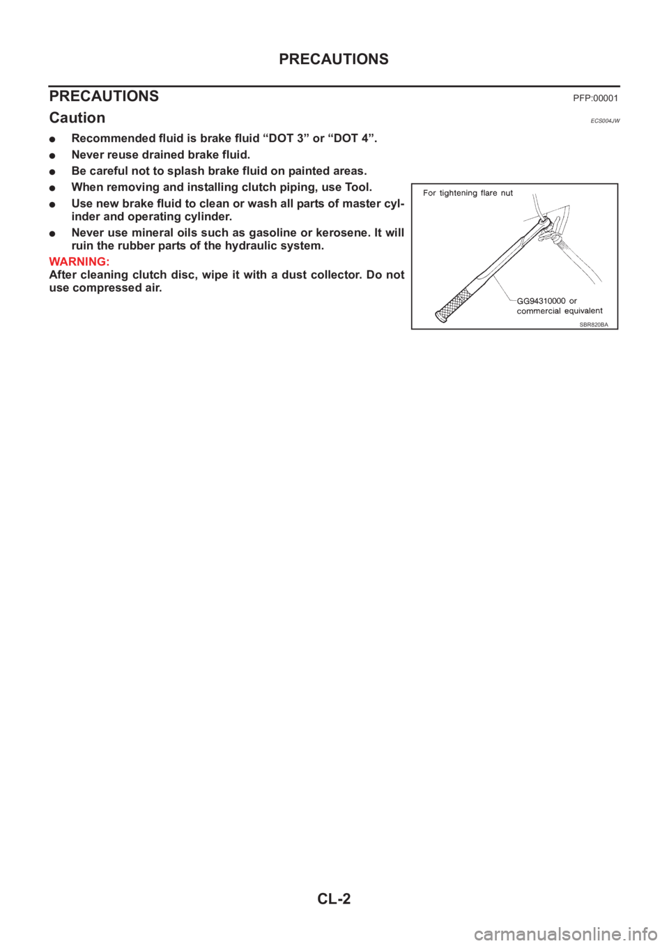
●When removing and installing clutch piping, use Tool.
●Use new brake fluid to clean or wash all parts of master cyl-
inder and operating cylinder.
●Never use mineral oils such as gasoline or kerosene. It will
ruin the rubber parts of the hydraulic system.
WARNING:
After cleaning clutch disc, wipe it with a dust collector. Do not
use compressed air.
SBR820BA
Page 1962 of 3833

CL-4
NOISE, VIBRATION, AND HARSHNESS (NVH) TROUBLESHOOTING
NOISE, VIBRATION, AND HARSHNESS (NVH) TROUBLESHOOTING
PFP:00003
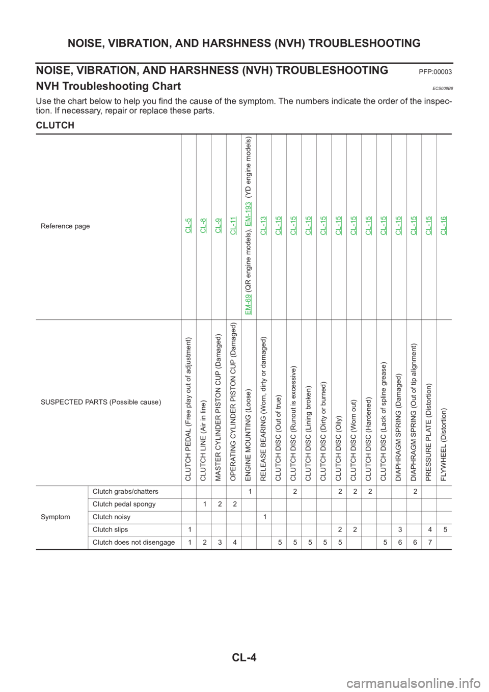
NVH Troubleshooting ChartECS008B8
Use the chart below to help you find the cause of the symptom. The numbers indicate the order of the inspec-
tion. If necessary, repair or replace these parts.
CLUTCH
Reference pageCL-5CL-8CL-9CL-11
EM-69
(QR engine models), EM-193
(YD engine models)
CL-13
CL-15CL-15CL-15CL-15CL-15CL-15CL-15CL-15CL-15CL-15CL-15CL-16
SUSPECTED PARTS (Possible cause)
CLUTCH PEDAL (Free play out of adjustment)
CLUTCH LINE (Air in line)
MASTER CYLINDER PISTON CUP (Damaged)
OPERATING CYLINDER PISTON CUP (Damaged)
ENGINE MOUNTING (Loose)
RELEASE BEARING (Worn, dirty or damaged)
CLUTCH DISC (Out of true)
CLUTCH DISC (Runout is excessive)
CLUTCH DISC (Lining broken)
CLUTCH DISC (Dirty or burned)
CLUTCH DISC (Oily)
CLUTCH DISC (Worn out)
CLUTCH DISC (Hardened)
CLUTCH DISC (Lack of spline grease)
DIAPHRAGM SPRING (Damaged)
DIAPHRAGM SPRING (Out of tip alignment)
PRESSURE PLATE (Distortion)
FLYWHEEL (Distortion)
SymptomClutch grabs/chatters 1 2 2 2 2 2
Clutch pedal spongy 1 2 2
Clutch noisy 1
Clutch slips 1 2 2 3 4 5
Clutch does not disengage 1 2 3 4 5 5 5 5 5 5 6 6 7
Page 1977 of 3833

MT-1
MANUAL TRANSAXLE
C TRANSMISSION/TRANSAXLE
CONTENTS
D
E
F
G
H
I
J
K
L
M
SECTION
A
B
MT
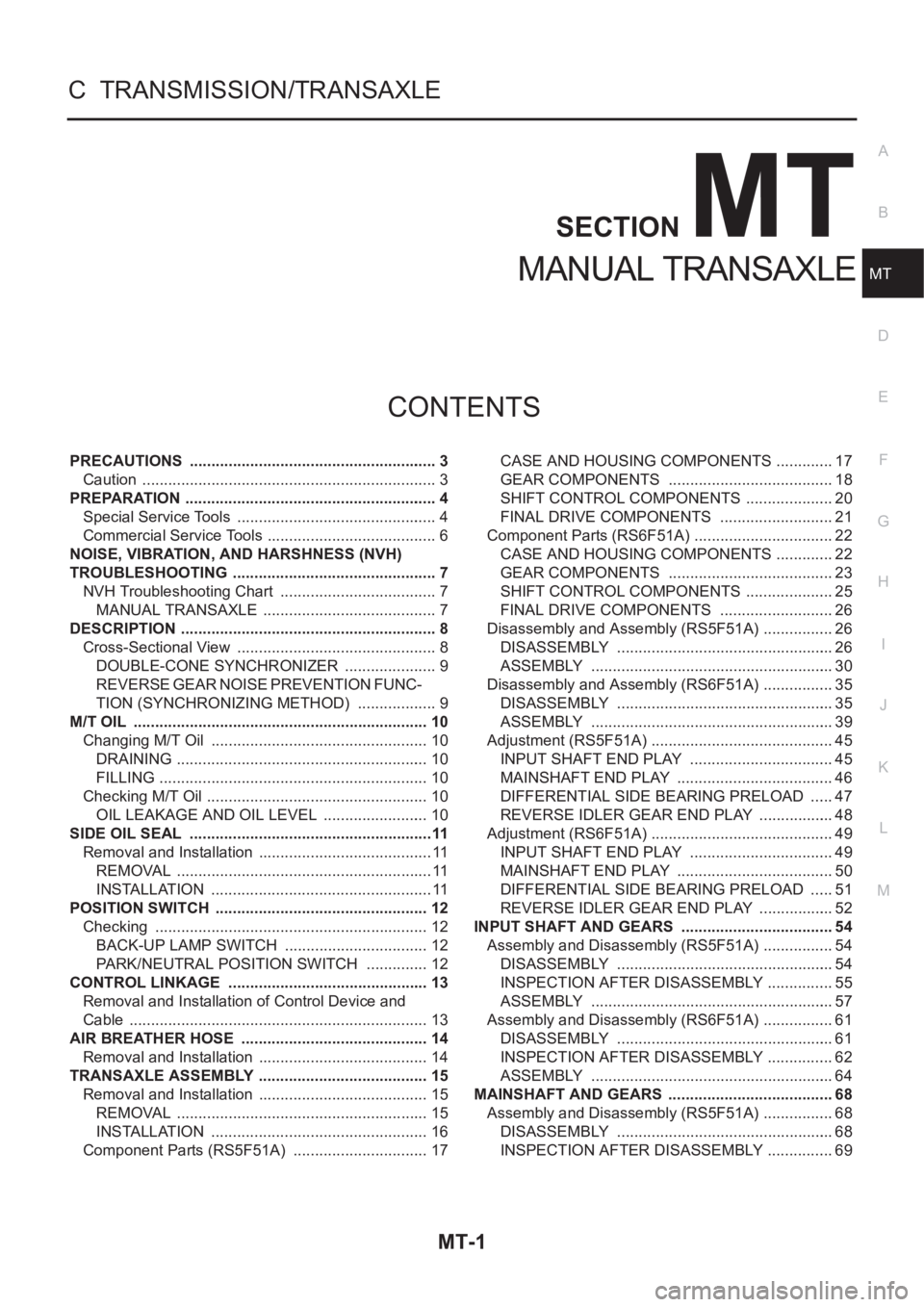
MANUAL TRANSAXLE
PRECAUTIONS .......................................................... 3
Caution ..................................................................... 3
PREPARATION ........................................................... 4
Special Service Tools ............................................... 4
Commercial Service Tools ........................................ 6
NOISE, VIBRATION, AND HARSHNESS (NVH)
TROUBLESHOOTING ................................................ 7
NVH Troubleshooting Chart ..................................... 7
MANUAL TRANSAXLE ......................................... 7
DESCRIPTION ............................................................ 8
Cross-Sectional View ............................................... 8
DOUBLE-CONE SYNCHRONIZER ...................... 9
REVERSE GEAR NOISE PREVENTION FUNC-
TION (SYNCHRONIZING METHOD) ................... 9
M/T OIL ..................................................................... 10
Changing M/T Oil ................................................... 10
DRAINING ........................................................... 10
FILLING ............................................................... 10
Checking M/T Oil .................................................... 10
OIL LEAKAGE AND OIL LEVEL ......................... 10
SIDE OIL SEAL .........................................................11
Removal and Installation ......................................... 11
REMOVAL ............................................................ 11
INSTALLATION .................................................... 11
POSITION SWITCH .................................................. 12
Checking ................................................................ 12
BACK-UP LAMP SWITCH .................................. 12
PARK/NEUTRAL POSITION SWITCH ............... 12
CONTROL LINKAGE ............................................... 13
Removal and Installation of Control Device and
Cable ...................................................................... 13
AIR BREATHER HOSE ............................................ 14
Removal and Installation ........................................ 14
TRANSAXLE ASSEMBLY ........................................ 15
Removal and Installation ........................................ 15
REMOVAL ........................................................... 15
INSTALLATION ................................................... 16
Component Parts (RS5F51A) ................................ 17CASE AND HOUSING COMPONENTS .............. 17
GEAR COMPONENTS ....................................... 18
SHIFT CONTROL COMPONENTS ..................... 20
FINAL DRIVE COMPONENTS ........................... 21
Component Parts (RS6F51A) ................................. 22
CASE AND HOUSING COMPONENTS .............. 22
GEAR COMPONENTS ....................................... 23
SHIFT CONTROL COMPONENTS ..................... 25
FINAL DRIVE COMPONENTS ........................... 26
Disassembly and Assembly (RS5F51A) ................. 26
DISASSEMBLY ................................................... 26
ASSEMBLY ......................................................... 30
Disassembly and Assembly (RS6F51A) ................. 35
DISASSEMBLY ................................................... 35
ASSEMBLY ......................................................... 39
Adjustment (RS5F51A) ........................................... 45
INPUT SHAFT END PLAY .................................. 45
MAINSHAFT END PLAY ..................................... 46
DIFFERENTIAL SIDE BEARING PRELOAD ...... 47
REVERSE IDLER GEAR END PLAY .................. 48
Adjustment (RS6F51A) ........................................... 49
INPUT SHAFT END PLAY .................................. 49
MAINSHAFT END PLAY ..................................... 50
DIFFERENTIAL SIDE BEARING PRELOAD ...... 51
REVERSE IDLER GEAR END PLAY .................. 52
INPUT SHAFT AND GEARS .................................... 54
Assembly and Disassembly (RS5F51A) ................. 54
DISASSEMBLY ................................................... 54
INSPECTION AFTER DISASSEMBLY ................ 55
ASSEMBLY ......................................................... 57
Assembly and Disassembly (RS6F51A) ................. 61
DISASSEMBLY ................................................... 61
INSPECTION AFTER DISASSEMBLY ................ 62
ASSEMBLY ......................................................... 64
MAINSHAFT AND GEARS ....................................... 68
Assembly and Disassembly (RS5F51A) ................. 68
DISASSEMBLY ................................................... 68
INSPECTION AFTER DISASSEMBLY ................ 69