2001 NISSAN X-TRAIL stop start
[x] Cancel search: stop startPage 3504 of 3833
LT-14
HEADLAMP - DAYTIME LIGHT SYSTEM -
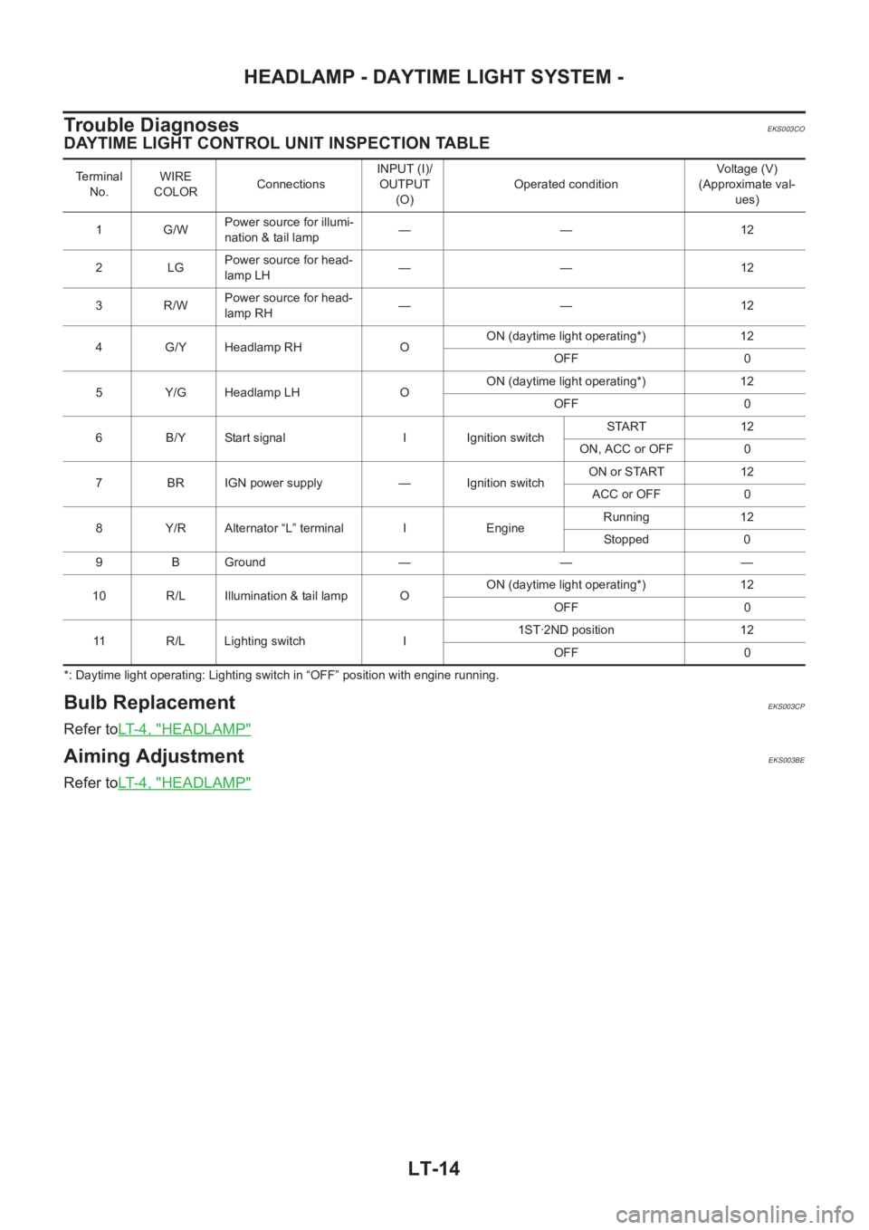
Trouble Diagnoses
EKS003CO
DAYTIME LIGHT CONTROL UNIT INSPECTION TABLE
*: Daytime light operating: Lighting switch in “OFF” position with engine running.
Bulb ReplacementEKS003CP
Refer toLT-4, "HEADLAMP"
Aiming AdjustmentEKS003BE
Refer toLT-4, "HEADLAMP"
Terminal
No.WIRE
COLORConnectionsINPUT (I)/
OUTPUT
(O)Operated conditionVoltage (V)
(Approximate val-
ues)
1 G/WPower source for illumi-
nation & tail lamp—— 12
2LGPower source for head-
lamp LH—— 12
3R/WPower source for head-
lamp RH—— 12
4 G/Y Headlamp RH OON (daytime light operating*) 12
OFF 0
5 Y/G Headlamp LH OON (daytime light operating*) 12
OFF 0
6 B/Y Start signal I Ignition switchSTART 12
ON, ACC or OFF 0
7 BR IGN power supply — Ignition switchON or START 12
ACC or OFF 0
8 Y/R Alternator “L” terminal I EngineRunning 12
Stopped 0
9 B Ground — — —
10 R/L Illumination & tail lamp OON (daytime light operating*) 12
OFF 0
11 R/L Lighting switch I1ST·2ND position 12
OFF 0
Page 3632 of 3833
WW-4
FRONT WIPER AND WASHER SYSTEM
FRONT WIPER AND WASHER SYSTEM
PFP:28810
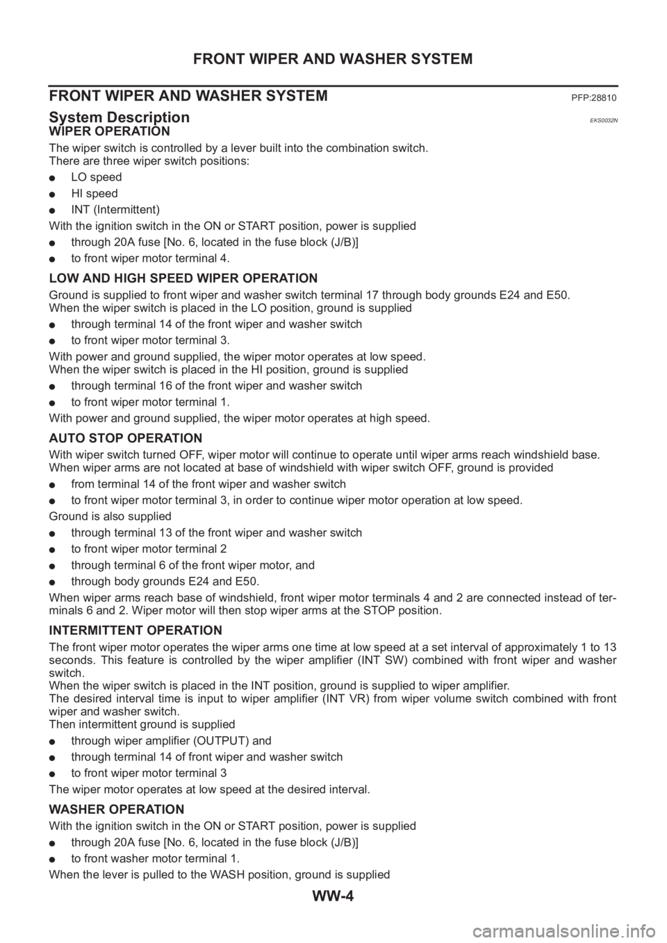
System DescriptionEKS0032N
WIPER OPERATION
The wiper switch is controlled by a lever built into the combination switch.
There are three wiper switch positions:
●LO speed
●HI speed
●INT (Intermittent)
With the ignition switch in the ON or START position, power is supplied
●through 20A fuse [No. 6, located in the fuse block (J/B)]
●to front wiper motor terminal 4.
LOW AND HIGH SPEED WIPER OPERATION
Ground is supplied to front wiper and washer switch terminal 17 through body grounds E24 and E50.
When the wiper switch is placed in the LO position, ground is supplied
●through terminal 14 of the front wiper and washer switch
●to front wiper motor terminal 3.
With power and ground supplied, the wiper motor operates at low speed.
When the wiper switch is placed in the HI position, ground is supplied
●through terminal 16 of the front wiper and washer switch
●to front wiper motor terminal 1.
With power and ground supplied, the wiper motor operates at high speed.
AUTO STOP OPERATION
With wiper switch turned OFF, wiper motor will continue to operate until wiper arms reach windshield base.
When wiper arms are not located at base of windshield with wiper switch OFF, ground is provided
●from terminal 14 of the front wiper and washer switch
●to front wiper motor terminal 3, in order to continue wiper motor operation at low speed.
Ground is also supplied
●through terminal 13 of the front wiper and washer switch
●to front wiper motor terminal 2
●through terminal 6 of the front wiper motor, and
●through body grounds E24 and E50.
When wiper arms reach base of windshield, front wiper motor terminals 4 and 2 are connected instead of ter-
minals 6 and 2. Wiper motor will then stop wiper arms at the STOP position.
INTERMITTENT OPERATION
The front wiper motor operates the wiper arms one time at low speed at a set interval of approximately 1 to 13
seconds. This feature is controlled by the wiper amplifier (INT SW) combined with front wiper and washer
switch.
When the wiper switch is placed in the INT position, ground is supplied to wiper amplifier.
The desired interval time is input to wiper amplifier (INT VR) from wiper volume switch combined with front
wiper and washer switch.
Then intermittent ground is supplied
●through wiper amplifier (OUTPUT) and
●through terminal 14 of front wiper and washer switch
●to front wiper motor terminal 3
The wiper motor operates at low speed at the desired interval.
WASHER OPERATION
With the ignition switch in the ON or START position, power is supplied
●through 20A fuse [No. 6, located in the fuse block (J/B)]
●to front washer motor terminal 1.
When the lever is pulled to the WASH position, ground is supplied
Page 3766 of 3833
PG-62
HARNESS
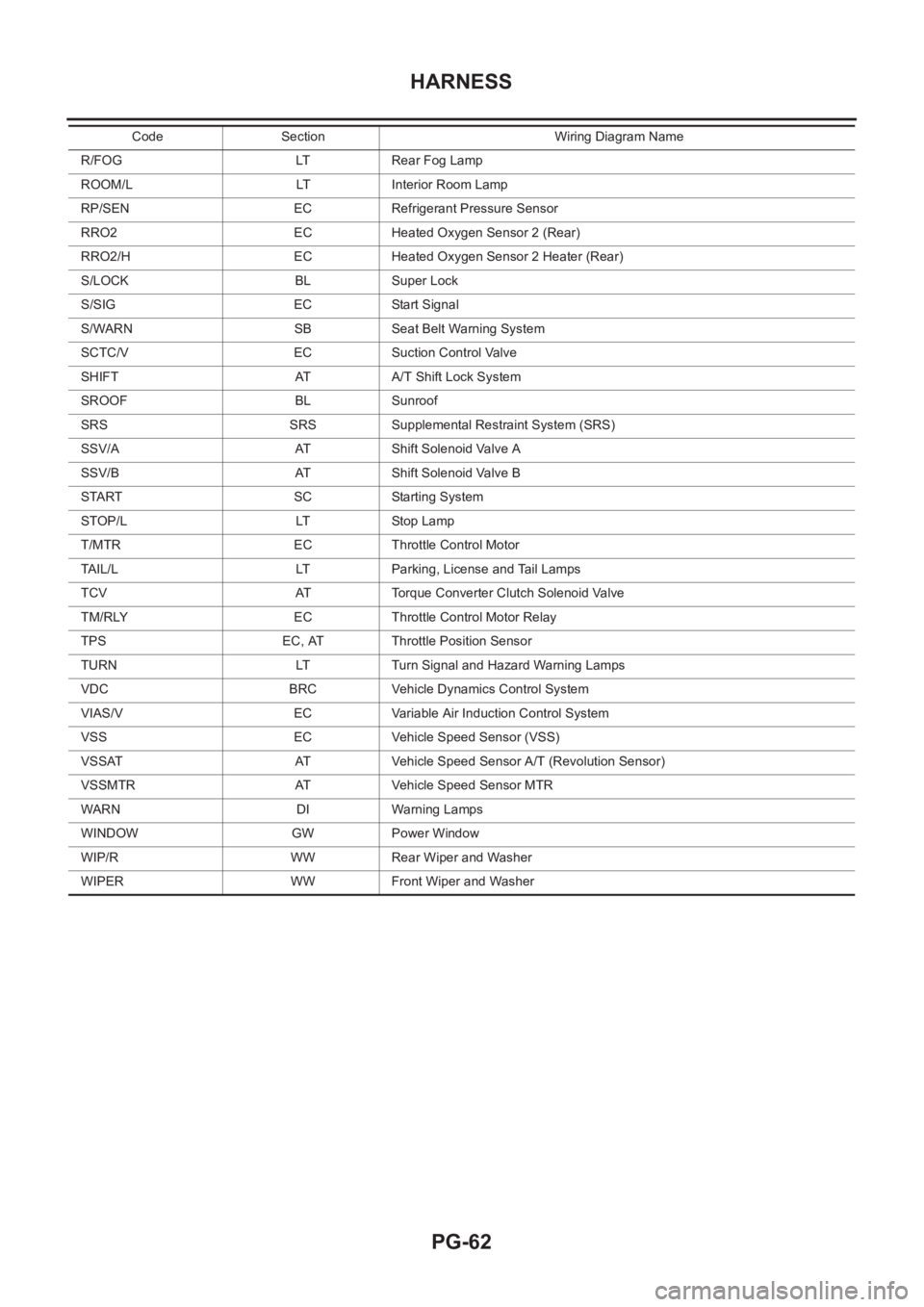
R/FOG LT Rear Fog Lamp
ROOM/L LT Interior Room Lamp
RP/SEN EC Refrigerant Pressure Sensor
RRO2 EC Heated Oxygen Sensor 2 (Rear)
RRO2/H EC Heated Oxygen Sensor 2 Heater (Rear)
S/LOCK BL Super Lock
S/SIG EC Start Signal
S/WARN SB Seat Belt Warning System
SCTC/V EC Suction Control Valve
SHIFT AT A/T Shift Lock System
SROOF BL Sunroof
SRS SRS Supplemental Restraint System (SRS)
SSV/A AT Shift Solenoid Valve A
SSV/B AT Shift Solenoid Valve B
START SC Starting System
STOP/L LT Stop Lamp
T/MTR EC Throttle Control Motor
TAIL/L LT Parking, License and Tail Lamps
TCV AT Torque Converter Clutch Solenoid Valve
TM/RLY EC Throttle Control Motor Relay
TPS EC, AT Throttle Position Sensor
TURN LT Turn Signal and Hazard Warning Lamps
VDC BRC Vehicle Dynamics Control System
VIAS/V EC Variable Air Induction Control System
VSS EC Vehicle Speed Sensor (VSS)
VSSAT AT Vehicle Speed Sensor A/T (Revolution Sensor)
VSSMTR AT Vehicle Speed Sensor MTR
WARN DI Warning Lamps
WINDOW GW Power Window
WIP/R WW Rear Wiper and Washer
WIPER WW Front Wiper and WasherCode Section Wiring Diagram Name
Page 3816 of 3833
MA-36
CHASSIS AND BODY MAINTENANCE
CAUTION:
Do not reuse gasket.
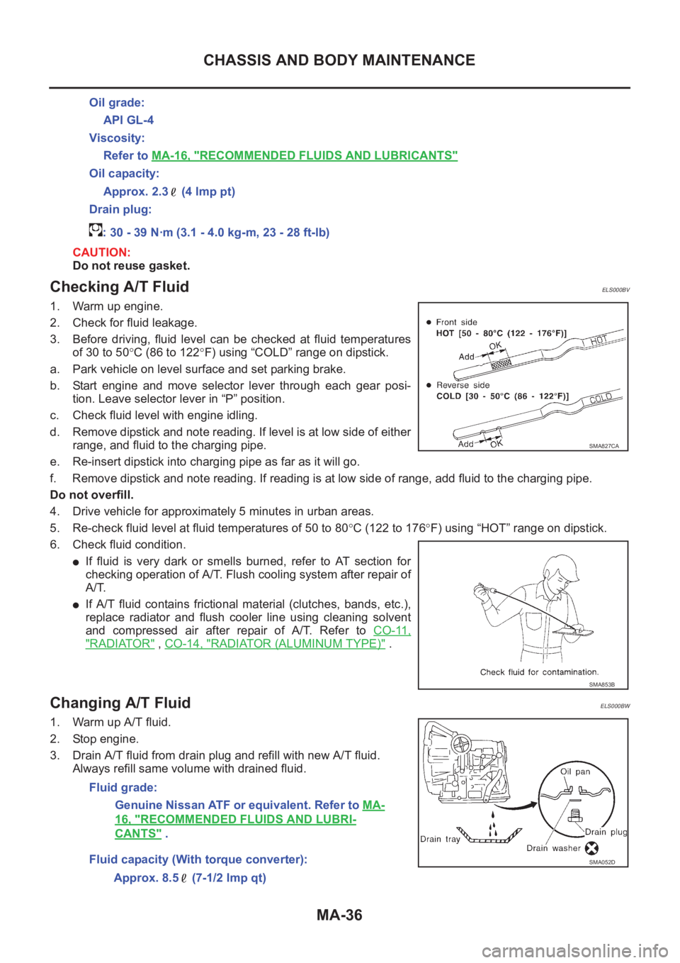
Checking A/T FluidELS000BV
1. Warm up engine.
2. Check for fluid leakage.
3. Before driving, fluid level can be checked at fluid temperatures
of 30 to 50°C (86 to 122°F) using “COLD” range on dipstick.
a. Park vehicle on level surface and set parking brake.
b. Start engine and move selector lever through each gear posi-
tion. Leave selector lever in “P” position.
c. Check fluid level with engine idling.
d. Remove dipstick and note reading. If level is at low side of either
range, and fluid to the charging pipe.
e. Re-insert dipstick into charging pipe as far as it will go.
f. Remove dipstick and note reading. If reading is at low side of range, add fluid to the charging pipe.
Do not overfill.
4. Drive vehicle for approximately 5 minutes in urban areas.
5. Re-check fluid level at fluid temperatures of 50 to 80°C (122 to 176°F) using “HOT” range on dipstick.
6. Check fluid condition.
●If fluid is very dark or smells burned, refer to AT section for
checking operation of A/T. Flush cooling system after repair of
A/T.
●If A/T fluid contains frictional material (clutches, bands, etc.),
replace radiator and flush cooler line using cleaning solvent
and compressed air after repair of A/T. Refer to CO-11,
"RADIATOR" , CO-14, "RADIATOR (ALUMINUM TYPE)" .
Changing A/T FluidELS000BW
1. Warm up A/T fluid.
2. Stop engine.
3. Drain A/T fluid from drain plug and refill with new A/T fluid.
Always refill same volume with drained fluid.Oil grade:
API GL-4
Viscosity:
Refer to MA-16, "
RECOMMENDED FLUIDS AND LUBRICANTS"
Oil capacity:
Approx. 2.3 (4 lmp pt)
Drain plug:
: 30 - 39 N·m (3.1 - 4.0 kg-m, 23 - 28 ft-lb)
SMA827CA
SMA853B
Fluid grade:
Genuine Nissan ATF or equivalent. Refer to MA-
16, "RECOMMENDED FLUIDS AND LUBRI-
CANTS" .
Fluid capacity (With torque converter):
Approx. 8.5 (7-1/2 lmp qt)
SMA052D
Page 3832 of 3833

IDX-8
ALPHABETICAL INDEX
Rear side window ............................................... GW-6
Rear suspension ............................................... RSU-5
Rear washer .................................................... WW-13
Rear window defogger ...................................... GW-10
Rear wiper ....................................................... WW-13
Refrigerant connection precaution ..................... ATC-5
Refrigerant discharging evacuating charging ATC-129
Refrigerant general precaution .......................... ATC-5
Refrigerant lines ............................................. ATC-129
Refrigerant pressure sensor ............. EC-412,EC-733,
EC-1099
,EC-1373,ATC-18,ATC-85,ATC-143
Refrigeration cycle ........................................... ATC-18
Release bearing (clutch) .................................... CL-13
Removal and installation (A/T) ......................... AT-418
Reverse idler shaft (M/T) ...................... MT-18,MT-23
Reverse lamp switch (M/T) - See Back-up lamp switch
(M/T) .................................................................. MT-12
Reverse main gear (M/T) ...................... MT-18,MT-23
Rocker cover(QR20DE•QR25DE) .................... EM-35
Rocker cover(YD22DDTi) ............................... EM-156
Room lamp ......................................................... LT-55
Room lamp - See Interior lamp ........................... LT-55
ROOM/L - Wiring diagram .................................. LT-55
RP/SEN - Wiring diagram EC-413,EC-734,EC-1100,
EC-1374
RRO2 - Wiring diagram ................... EC-678,EC-1327
RRO2/H - Wiring diagram ................ EC-663,EC-1313
S
S/LOCK - Wiring diagram ....................... BL-13
,BL-32
S/SIG - Wiring diagram .... EC-402,EC-723,EC-1089,
EC-1363
,EC-1566
SCTC/V - Wiring diagram .............................. EC-1522
Seat belt inspection .......................................... MA-42
Seat belt pre-tensioner disposal ..................... SRS-41
Seat belt, front ..................................................... SB-3
Seat belt, rear ...................................................... SB-4
Seat, front ............................................................ SE-7
Seat, rear ........................................................... SE-11
Self-diagnosis (Transfer) ................................... TF-45
SEN/PW - Wiring diagram ................. EC-342,EC-622
Sheft warning system ........................................ BL-76
SHIFT - Wiring diagram ................................... AT-407
Shift control components (M/T) ............. MT-20,MT-25
Shift fork (M/T) ...................................... MT-20,MT-25
Shift lever ........................................................... MT-13
Shift lock system .............................................. AT-406
Shift schedule .................................................. AT-521
Shift solenoid valve A (A/T) .. AT-131,AT-136,AT-148
Shift solenoid valve B (A/T) ............... AT-131,AT-136
Side air bag (satellite) sensor ......................... SRS-38
Side trim .............................................................. EI-26
Side window - See Rear side window ................. GW-6
Spark plug replacement(QR20DE•QR25DE) ... MA-24
Spark plug(QR20DE•QR25DE) ........................ EM-30
Specification value EC-111,EC-502,EC-843,EC-1188
Speedometer ............................................. DI-4,DI-24
Spiral cable ..................................................... SRS-33
Spot lamp ........................................................... LT-65
SROOF - Wiring diagram ..................................... RF-4
SRS - See Supplemental Restraint System ..... SRS-5
SRS - Wiring diagram/LHD ............................. SRS-10
SRS - Wiring diagram/RHD ............................ SRS-12
SRS Trouble diagnoses .................................... SRS-7
Stall test (A/T) ...................................... AT-64,AT-265
Standardized relay ............................................ PG-72
START - Wiring diagram ....................... SC-21,SC-22
Start signal ....... EC-401,EC-722,EC-1088,EC-1362,
EC-1566
Starter ................................................................ SC-20
Starting system .................................................. SC-20
Steering gear and linkage inspection ................ MA-40
Steering knuckle ................................................ FAX-7
Steering linkage ................................................. PS-12
Steering wheel and column ....................... PS-6,PS-9
Stop lamp ................................................ LT-26,LT-42
Stop lamp switch EC-349,EC-625,EC-1068,EC-1301
STOP/L - Wiring diagram ........................ LT-26,LT-42
Strut (rear) ........................................................ RSU-8
Suction control valve ...................................... EC-1519
Sunload sensor ............. ATC-105,ATC-107,ATC-114
Sunroof ................................................................ RF-3
Super lock .......................................................... BL-29
Supplemental Restraint System ....................... SRS-5
Supplemental restraint system - Wiring diagram/LHD ..
SRS-10
Supplemental restraint system - Wiring diagram/RHD .
SRS-12
Suspension ....................................................... MA-41
Symbols and abbreviations ........................ GI-9,GI-21
Symptom matrix chart .......... EC-77,EC-469,EC-809,
EC-1156
,EC-1416
Synchronizer (M/T) ............................... MT-18,MT-23
System readiness test (SRT) code ..... EC-48,EC-781
T
T/MTR - Wiring diagram ............... EC-1014
,EC-1277
Tachometer ................................................ DI-4,DI-24
Tail lamp ................................................. LT-30,LT-40
TAIL/L - Wiring diagram ..................................... LT-30
Tailgate lamp ..................................................... LT-30
TCM circuit diagram ........................................... AT-15
TCM inspection table ......................... AT-106,AT-306
THEFT - Wiring diagram .................................... BL-76
Thermal protector ........................................... ATC-85
Thermostat(QR20DE•QR25DE) ....................... CO-20
Thermostat(YD22DDTi) .................................... CO-42
Three way catalyst function .............. EC-239,EC-968
Three way catalyst precautions ............................ GI-5
Three way catalyst(QR20DE•QR25DE) ........... EM-24
Throttle control motor ........................ EC-290,EC-598
Throttle control motor relay EC-285,EC-593,EC-1018,
EC-1281
Throttle position sensor (TPS) ......... EC-154,EC-212,
EC-337
,EC-339,EC-367,EC-528,EC-540,EC-617,
EC-619
,EC-644,EC-886,EC-1214