2001 NISSAN X-TRAIL engine overheat
[x] Cancel search: engine overheatPage 358 of 3833
EC-8
Wiring Diagram .....................................................595
Diagnostic Procedure ...........................................596
Component Inspection ..........................................597
DTC P1128 THROTTLE CONTROL MOTOR .........598
Component Description ........................................598
ECM Terminals and Reference Value ...................598
On Board Diagnosis Logic ....................................598
DTC Confirmation Procedure ...............................598
Wiring Diagram .....................................................600
Diagnostic Procedure ...........................................601
Component Inspection ..........................................602
Remove and Installation .......................................602
DTC P1217 ENGINE OVER TEMPERATURE ........603
System Description ...............................................603
CONSULT-II Reference Value in Data Monitor Mode
.603
ECM Terminals and Reference Value ...................604
On Board Diagnosis Logic ....................................604
Overall Function Check ........................................605
Wiring Diagram .....................................................607
Diagnostic Procedure ...........................................608
Main 12 Causes of Overheating ...........................615
Component Inspection ..........................................616
DTC P1225 TP SENSOR ........................................617
Component Description ........................................617
On Board Diagnosis Logic ....................................617
DTC Confirmation Procedure ...............................617
Diagnostic Procedure ...........................................618
Remove and Installation .......................................618
DTC P1226 TP SENSOR ........................................619
Component Description ........................................619
On Board Diagnosis Logic ....................................619
DTC Confirmation Procedure ...............................619
Diagnostic Procedure ...........................................620
Remove and Installation .......................................620
DTC P1229 SENSOR POWER SUPPLY ................621
On Board Diagnosis Logic ....................................621
DTC Confirmation Procedure ...............................621
Wiring Diagram .....................................................622
Diagnostic Procedure ...........................................623
DTC P1805 BRAKE SWITCH .................................625
Description ............................................................625
CONSULT-II Reference Value in Data Monitor Mode
.625
ECM Terminals and Reference Value ...................625
On Board Diagnosis Logic ....................................625
DTC Confirmation Procedure ...............................625
Wiring Diagram .....................................................627
Diagnostic Procedure ...........................................628
Component Inspection ..........................................629
DTC P2122, P2123 APP SENSOR .........................631
Component Description ........................................631
CONSULT-II Reference Value in Data Monitor Mode
.631
ECM Terminals and Reference Value ...................631
On Board Diagnosis Logic ....................................632
DTC Confirmation Procedure ...............................632
Wiring Diagram .....................................................633
Diagnostic Procedure ...........................................634Component Inspection ..........................................636
Remove and Installation .......................................636
DTC P2127, P2128 APP SENSOR .........................637
Component Description ........................................637
CONSULT-II Reference Value in Data Monitor Mode
.637
ECM Terminals and Reference Value ...................637
On Board Diagnosis Logic ....................................638
DTC Confirmation Procedure ................................639
Wiring Diagram .....................................................640
Diagnostic Procedure ............................................641
Component Inspection ..........................................643
Remove and Installation .......................................643
DTC P2135 TP SENSOR ........................................644
Component Description ........................................644
CONSULT-II Reference Value in Data Monitor Mode
.644
ECM Terminals and Reference Value ...................644
On Board Diagnosis Logic ....................................645
DTC Confirmation Procedure ................................645
Wiring Diagram .....................................................647
Diagnostic Procedure ............................................648
Component Inspection ..........................................650
Remove and Installation .......................................650
DTC P2138 APP SENSOR ......................................651
Component Description ........................................651
CONSULT-II Reference Value in Data Monitor Mode
.651
ECM Terminals and Reference Value ...................651
On Board Diagnosis Logic ....................................652
DTC Confirmation Procedure ................................652
Wiring Diagram .....................................................653
Diagnostic Procedure ............................................654
Component Inspection ..........................................656
Remove and Installation .......................................656
HO2S1 HEATER ......................................................657
Description ............................................................657
CONSULT-II Reference Value in Data Monitor Mode
.657
ECM Terminals and Reference Value ...................657
Wiring Diagram ....................................................
.658
Diagnostic Procedure ............................................659
Component Inspection ..........................................661
Removal and Installation .......................................661
HO2S2 HEATER ......................................................662
Description ............................................................662
CONSULT-II Reference Value in Data Monitor Mode
.662
ECM Terminals and Reference Value ...................662
Wiring Diagram .....................................................663
Diagnostic Procedure ............................................664
Component Inspection ..........................................666
Removal and Installation .......................................666
IAT SENSOR ...........................................................667
Component Description ........................................667
Wiring Diagram .....................................................668
Diagnostic Procedure ............................................669
Component Inspection ..........................................670
Removal and Installation .......................................670
Page 363 of 3833
EC-13
C
D
E
F
G
H
I
J
K
L
M
ECA On Board Diagnosis Logic ..................................1018
DTC Confirmation Procedure ..............................1018
Wiring Diagram ...................................................1020
Diagnostic Procedure ..........................................1021
Component Inspection ........................................1022
DTC P1143 HO2S1 ................................................1023
Component Description .......................................1023
CONSULT-II Reference Value in Data Monitor Mode
1023
ECM Terminals and Reference Value .................1023
On Board Diagnosis Logic ..................................1024
DTC Confirmation Procedure ..............................1024
Overall Function Check .......................................1025
Diagnostic Procedure ..........................................1025
Component Inspection ........................................1027
Removal and Installation .....................................1028
DTC P1144 HO2S1 ................................................1029
Component Description .......................................1029
CONSULT-II Reference Value in Data Monitor Mode
1029
ECM Terminals and Reference Value .................1029
On Board Diagnosis Logic ..................................1030
DTC Confirmation Procedure ..............................1030
Overall Function Check .......................................1031
Diagnostic Procedure ..........................................1031
Component Inspection ........................................1033
Removal and Installation .....................................1034
DTC P1146 HO2S2 ................................................1035
Component Description .......................................1035
CONSULT-II Reference Value in Data Monitor Mode
1035
ECM Terminals and Reference Value .................1035
On Board Diagnosis Logic ..................................1035
DTC Confirmation Procedure ..............................1036
Overall Function Check .......................................1037
Wiring Diagram ...................................................1038
Diagnostic Procedure ..........................................1039
Component Inspection ........................................1040
Removal and Installation .....................................1041
DTC P1147 HO2S2 ................................................1042
Component Description .......................................1042
CONSULT-II Reference Value in Data Monitor Mode
1042
ECM Terminals and Reference Value .................1042
On Board Diagnosis Logic ..................................1042
DTC Confirmation Procedure ..............................1043
Overall Function Check .......................................1044
Wiring Diagram ...................................................1045
Diagnostic Procedure ..........................................1046
Component Inspection ........................................1047
Removal and Installation .....................................1048
DTC P1212 ESP/TCS/ABS COMMUNICATION
LINE .......................................................................1049
Description ..........................................................1049
On Board Diagnosis Logic ..................................1049
DTC Confirmation Procedure ..............................1049
Diagnostic Procedure ..........................................1049
DTC P1217 ENGINE OVER TEMPERATURE ......1050
System Description .............................................1050CONSULT-II Reference Value in Data Monitor Mode
1050
ECM Terminals and Reference Value ..................1051
On Board Diagnosis Logic ...................................1051
Overall Function Check .......................................1052
Wiring Diagram ....................................................1054
Diagnostic Procedure ..........................................1055
Main 12 Causes of Overheating ..........................1062
Component Inspection .........................................1063
DTC P1706 PNP SWITCH .....................................1064
Component Description .......................................1064
CONSULT-II Reference Value in Data Monitor Mode
1064
ECM Terminals and Reference Value ..................1064
On Board Diagnosis Logic ...................................1064
DTC Confirmation Procedure ..............................1064
Overall Function Check .......................................1065
Wiring Diagram ....................................................1066
Diagnostic Procedure ..........................................1067
DTC P1805 BRAKE SWITCH ................................1068
Description ...........................................................1068
CONSULT-II Reference Value in Data Monitor Mode
1068
ECM Terminals and Reference Value ..................1068
On Board Diagnosis Logic ...................................1068
DTC Confirmation Procedure ..............................1068
Wiring Diagram ....................................................1070
Diagnostic Procedure ..........................................1071
Component Inspection .........................................1072
IGNITION SIGNAL .................................................1074
Component Description .......................................1074
ECM Terminals and Reference Value ..................1074
Wiring Diagram ....................................................1075
Diagnostic Procedure ..........................................1077
Component Inspection .........................................1081
Removal and Installation .....................................1082
INJECTOR CIRCUIT ..............................................1083
Component Description .......................................1083
CONSULT-II Reference Value in Data Monitor Mode
1083
ECM Terminals and Reference Value ..................1083
Wiring Diagram ....................................................
1084
Diagnostic Procedure ..........................................1085
Component Inspection .........................................1087
Removal and Installation .....................................1087
START SIGNAL .....................................................1088
CONSULT-II Reference Value in Data Monitor Mode
1088
ECM Terminals and Reference Value ..................1088
Wiring Diagram ....................................................1089
Diagnostic Procedure ..........................................1090
FUEL PUMP CIRCUIT ...........................................1092
Description ...........................................................1092
CONSULT-II Reference Value in Data Monitor Mode
1092
ECM Terminals and Reference Value ..................1092
Wiring Diagram ....................................................1094
Diagnostic Procedure ..........................................1095
Page 366 of 3833
EC-16
On Board Diagnosis Logic ...................................1275
DTC Confirmation Procedure ..............................1276
Wiring Diagram ....................................................1277
Diagnostic Procedure ..........................................1278
Component Inspection .........................................1280
DTC P1123 THROTTLE CONTROL MOTOR RELAY 1281
Component Description .......................................1281
CONSULT-II Reference Value in Data Monitor Mode
1281
ECM Terminals and Reference Value ..................1281
On Board Diagnosis Logic ...................................1281
DTC Confirmation Procedure ..............................1281
Wiring Diagram ....................................................1283
Diagnostic Procedure ..........................................1284
Component Inspection .........................................1285
DTC P1212 ESP/TCS/ABS COMMUNICATION
LINE ........................................................................1286
Description ...........................................................1286
On Board Diagnosis Logic ...................................1286
DTC Confirmation Procedure ..............................1286
Diagnostic Procedure ..........................................1286
DTC P1217 ENGINE OVER TEMPERATURE .......1287
System Description ..............................................1287
CONSULT-II Reference Value in Data Monitor Mode
1287
ECM Terminals and Reference Value ..................1288
On Board Diagnosis Logic ...................................1288
Overall Function Check .......................................1289
Wiring Diagram ....................................................1291
Diagnostic Procedure ..........................................1292
Main 12 Causes of Overheating ..........................1299
Component Inspection .........................................1300
DTC P1805 BRAKE SWITCH ................................1301
Description ...........................................................1301
CONSULT-II Reference Value in Data Monitor Mode
1301
ECM Terminals and Reference Value ..................1301
On Board Diagnosis Logic ...................................1301
FAIL-SAFE MODE ...............................................1301
DTC Confirmation Procedure ..............................1301
Wiring Diagram ....................................................1303
Diagnostic Procedure ..........................................1304
Component Inspection .........................................1305
HO2S1 HEATER ....................................................1307
Description ...........................................................1307
CONSULT-II Reference Value in Data Monitor Mode
1307
ECM Terminals and Reference Value ..................1307
Wiring Diagram ....................................................1308
Diagnostic Procedure ..........................................1309
Component Inspection .........................................1311
Removal and Installation .....................................1311
HO2S2 HEATER ....................................................1312
Description ...........................................................1312
CONSULT-II Reference Value in Data Monitor Mode
1312
ECM Terminals and Reference Value ..................1312
Wiring Diagram ....................................................1313
Diagnostic Procedure ..........................................1314Component Inspection .........................................1315
Removal and Installation ......................................1315
IAT SENSOR ..........................................................1316
Component Description .......................................1316
Wiring Diagram ....................................................1317
Diagnostic Procedure ........................................... 1318
Component Inspection .........................................1319
Removal and Installation ......................................1319
HO2S1 ....................................................................1320
Component Description .......................................1320
CONSULT-II Reference Value in Data Monitor Mode
1320
ECM Terminals and Reference Value ..................1320
Wiring Diagram ....................................................1321
Diagnostic Procedure ........................................... 1322
Component Inspection .........................................1323
Removal and Installation ......................................1325
HO2S2 ....................................................................1326
Component Description .......................................1326
CONSULT-II Reference Value in Data Monitor Mode
1326
ECM Terminals and Reference Value ..................1326
Wiring Diagram ....................................................1327
Diagnostic Procedure ........................................... 1328
Component Inspection .........................................1329
Removal and Installation ......................................1330
IGNITION SIGNAL .................................................1331
Component Description .......................................1331
ECM Terminals and Reference Value ..................1331
Wiring Diagram ....................................................1332
Diagnostic Procedure ........................................... 1334
Component Inspection .........................................1338
Removal and Installation ......................................1339
EVAP CANISTER PURGE VOLUME CONTROL
SOLENOID VALVE ................................................. 1340
Description ...........................................................1340
CONSULT-II Reference Value in Data Monitor Mode
1340
ECM Terminals and Reference Value ..................1340
Wiring Diagram ....................................................1342
Diagnostic Procedure ........................................... 1343
Component Inspection .........................................1346
Removal and Installation ......................................1346
IVT CONTROL SOLENOID VALVE .......................1347
Description ...........................................................1347
CONSULT-II Reference Value in Data Monitor Mode
1347
ECM Terminals and Reference Value ..................1348
Wiring Diagram ....................................................1349
Diagnostic Procedure ........................................... 1350
Component Inspection .........................................1352
Removal and Installation ......................................1352
PNP SWITCH .........................................................1353
Component Description .......................................1353
CONSULT-II Reference Value in Data Monitor Mode
1353
ECM Terminals and Reference Value ..................1353
Wiring Diagram ....................................................1354
Diagnostic Procedure ........................................... 1355
Page 368 of 3833
EC-18
CONSULT-II Reference Value in Data Monitor Mode
1451
ECM Terminals and Reference Value ..................1451
On Board Diagnosis Logic ...................................1452
DTC Confirmation Procedure ..............................1452
Wiring Diagram ....................................................1453
Diagnostic Procedure ..........................................1454
Component Inspection .........................................1455
Removal and Installation .....................................1455
DTC P0115 ENGINE COOLANT TEMPERATURE
(ECT) SENSOR (CIRCUIT) ....................................1456
Description ...........................................................1456
On Board Diagnosis Logic ...................................1456
DTC Confirmation Procedure ..............................1456
Wiring Diagram ....................................................1457
Diagnostic Procedure ..........................................1458
Component Inspection .........................................1459
Removal and Installation .....................................1459
DTC P0120 ACCELERATOR PEDAL POSITION
SENSOR .................................................................1460
Description ...........................................................1460
CONSULT-II Reference Value in Data Monitor Mode
1460
ECM Terminals and Reference Value ..................1460
On Board Diagnosis Logic ...................................1461
DTC Confirmation Procedure ..............................1461
Wiring Diagram ....................................................1462
Diagnostic Procedure ..........................................1463
Component Inspection .........................................1466
Removal and Installation .....................................1467
DTC P0190 COMMON RAIL FUEL PRESSURE
SENSOR .................................................................1468
Description ...........................................................1468
CONSULT-II Reference Value in Data Monitor Mode
1468
ECM Terminals and Reference Value ..................1468
On Board Diagnosis Logic ...................................1468
DTC Confirmation Procedure ..............................1468
Wiring Diagram ....................................................1469
Diagnostic Procedure ..........................................1470
Component Inspection .........................................1471
Removal and Installation .....................................1471
DTC P0201 - P0204 FUEL INJECTOR ..................1472
Description ...........................................................1472
CONSULT-II Reference Value in Data Monitor Mode
1472
ECM Terminals and Reference Value ..................1472
On Board Diagnosis Logic ...................................1473
DTC Confirmation Procedure ..............................1474
Wiring Diagram ....................................................1475
Diagnostic Procedure ..........................................1477
Component Inspection .........................................
1478
Removal and Installation .....................................1478
DTC P0335 CRANKSHAFT POSISTION SENSOR
(TDC) ......................................................................1479
Description ...........................................................1479
CONSULT-II Reference Value in Data Monitor Mode
1479
ECM Terminals and Reference Value ..................1479On Board Diagnosis Logic ...................................1480
DTC Confirmation Procedure ...............................1480
Wiring Diagram ....................................................1481
Diagnostic Procedure ........................................... 1482
Component Inspection .........................................1482
Removal and Installation ......................................1483
DTC P0340 CAMSHAFT POSITION SENSOR ......1484
Description ...........................................................1484
ECM Terminals and Reference Value ..................1484
On Board Diagnosis Logic ...................................1484
DTC Confirmation Procedure ...............................1484
Wiring Diagram ....................................................1486
Diagnostic Procedure ........................................... 1487
Component Inspection .........................................1487
Removal and Installation ......................................1488
DTC P0500 VEHICLE SPEED SENSOR (VSS) .....1489
Description ...........................................................1489
ECM Terminals and Reference Value ..................1489
On Board Diagnosis Logic ...................................1489
Overall Function Check ........................................1489
Wiring Diagram ....................................................1490
Diagnostic Procedure ........................................... 1492
DTC P1107 ABSOLUTE PRESSURE SENSOR ....1494
Description ...........................................................1494
On Board Diagnosis Logic ...................................1494
DTC Confirmation Procedure ...............................1494
Diagnostic Procedure ........................................... 1494
DTC P1180 FUEL TEMPERATURE SENSOR .......1496
Description ...........................................................1496
CONSULT-II Reference Value in Data Monitor Mode
1496
ECM Terminals and Reference Value ..................1496
On Board Diagnosis Logic ...................................1496
DTC Confirmation Procedure ...............................1496
Wiring Diagram ....................................................1497
Diagnostic Procedure ........................................... 1498
Removal and Installation ......................................1498
DTC P1211 TCS CONTROL UNIT .........................1499
Description ...................................................
........1499
On Board Diagnosis Logic ...................................1499
DTC Confirmation Procedure ...............................1499
Diagnostic Procedure ........................................... 1499
DTC P1212 TCS COMMUNICATION LINE ............1500
Description ...........................................................1500
On Board Diagnosis Logic ...................................1500
DTC Confirmation Procedure ...............................1500
Diagnostic Procedure ........................................... 1500
DTC P1216 EDU .....................................................1501
Description ...........................................................1501
ECM Terminals and Reference Value ..................1501
On Board Diagnosis Logic ...................................1502
DTC Confirmation Procedure ...............................1502
Wiring Diagram ....................................................1503
Diagnostic Procedure ........................................... 1505
Removal and Installation ......................................1507
DTC P1217 OVERHEAT (COOLING SYSTEM) .....1508
Description ...........................................................1508
CONSULT-II Reference Value in Data Monitor Mode
1508
Page 369 of 3833
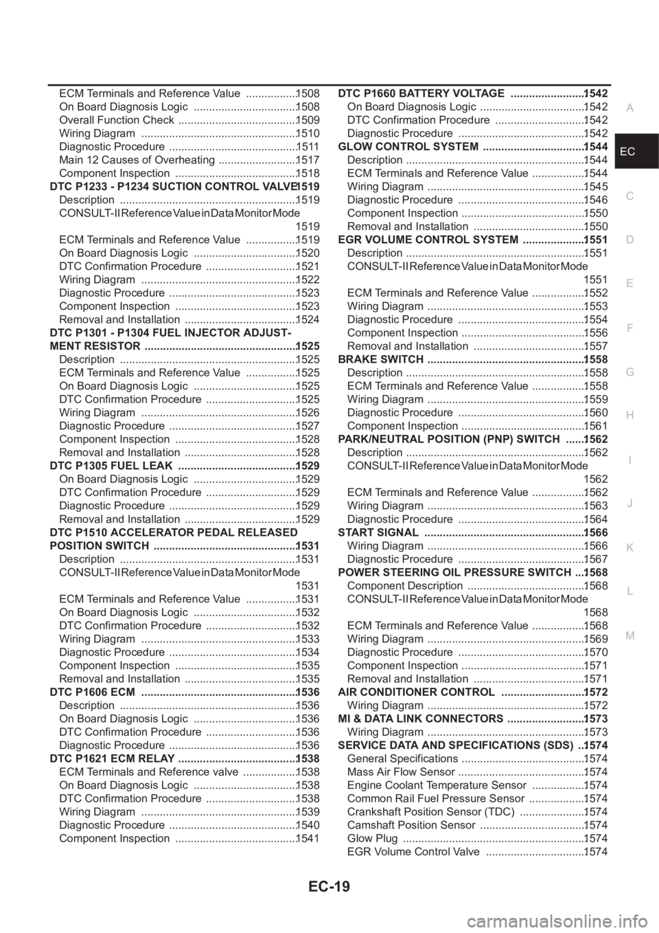
EC-19
C
D
E
F
G
H
I
J
K
L
M
ECA ECM Terminals and Reference Value .................1508
On Board Diagnosis Logic ..................................1508
Overall Function Check .......................................1509
Wiring Diagram ...................................................1510
Diagnostic Procedure ..........................................1511
Main 12 Causes of Overheating ..........................1517
Component Inspection ........................................1518
DTC P1233 - P1234 SUCTION CONTROL VALVE 1519
Description ..........................................................1519
CONSULT-II Reference Value in Data Monitor Mode
1519
ECM Terminals and Reference Value .................1519
On Board Diagnosis Logic ..................................1520
DTC Confirmation Procedure ..............................1521
Wiring Diagram ...................................................1522
Diagnostic Procedure ..........................................1523
Component Inspection ........................................1523
Removal and Installation .....................................1524
DTC P1301 - P1304 FUEL INJECTOR ADJUST-
MENT RESISTOR .................................................. 1525
Description ..........................................................1525
ECM Terminals and Reference Value .................1525
On Board Diagnosis Logic ..................................1525
DTC Confirmation Procedure ..............................1525
Wiring Diagram ...................................................1526
Diagnostic Procedure ..........................................1527
Component Inspection ........................................1528
Removal and Installation .....................................1528
DTC P1305 FUEL LEAK .......................................1529
On Board Diagnosis Logic ..................................1529
DTC Confirmation Procedure ..............................1529
Diagnostic Procedure ..........................................1529
Removal and Installation .....................................1529
DTC P1510 ACCELERATOR PEDAL RELEASED
POSITION SWITCH ...............................................1531
Description ..........................................................1531
CONSULT-II Reference Value in Data Monitor Mode
1531
ECM Terminals and Reference Value .................1531
On Board Diagnosis Logic ..................................1532
DTC Confirmation Procedure ..............................1532
Wiring Diagram ...................................................1533
Diagnostic Procedure ..........................................1534
Component Inspection ........................................1535
Removal and Installation .....................................1535
DTC P1606 ECM ...................................................1536
Description ..........................................................1536
On Board Diagnosis Logic ..................................1536
DTC Confirmation Procedure ..............................
1536
Diagnostic Procedure ..........................................1536
DTC P1621 ECM RELAY .......................................1538
ECM Terminals and Reference valve ..................1538
On Board Diagnosis Logic ..................................1538
DTC Confirmation Procedure ..............................1538
Wiring Diagram ...................................................1539
Diagnostic Procedure ..........................................1540
Component Inspection ........................................1541DTC P1660 BATTERY VOLTAGE .........................1542
On Board Diagnosis Logic ...................................1542
DTC Confirmation Procedure ..............................1542
Diagnostic Procedure ..........................................1542
GLOW CONTROL SYSTEM ..................................1544
Description ...........................................................1544
ECM Terminals and Reference Value ..................1544
Wiring Diagram ....................................................1545
Diagnostic Procedure ..........................................1546
Component Inspection .........................................1550
Removal and Installation .....................................1550
EGR VOLUME CONTROL SYSTEM .....................1551
Description ...........................................................1551
CONSULT-II Reference Value in Data Monitor Mode
1551
ECM Terminals and Reference Value ..................1552
Wiring Diagram ....................................................1553
Diagnostic Procedure ..........................................1554
Component Inspection .........................................1556
Removal and Installation .....................................1557
BRAKE SWITCH ....................................................1558
Description ...........................................................1558
ECM Terminals and Reference Value ..................1558
Wiring Diagram ....................................................1559
Diagnostic Procedure ..........................................1560
Component Inspection .........................................1561
PARK/NEUTRAL POSITION (PNP) SWITCH .......1562
Description ...........................................................1562
CONSULT-II Reference Value in Data Monitor Mode
1562
ECM Terminals and Reference Value ..................1562
Wiring Diagram ....................................................1563
Diagnostic Procedure ..........................................1564
START SIGNAL .....................................................1566
Wiring Diagram ....................................................1566
Diagnostic Procedure ..........................................1567
POWER STEERING OIL PRESSURE SWITCH ....1568
Component Description .......................................1568
CONSULT-II Reference Value in Data Monitor Mode
1568
ECM Terminals and Reference Value ..................1568
Wiring Diagram ....................................................1569
Diagnostic Procedure ..........................................1570
Component Inspection .........................................1571
Removal and Installation .....................................1571
AIR CONDITIONER CONTROL ............................1572
Wiring Diagram ....................................................1572
MI & DATA LINK CONNECTORS ..........................1573
Wiring Diagram ....................................................1573
SERVICE DATA AND SPECIFICATIONS (SDS) ...1574
General Specifications ......................................... 1574
Mass Air Flow Sensor ..........................................1574
Engine Coolant Temperature Sensor ..................1574
Common Rail Fuel Pressure Sensor ...................1574
Crankshaft Position Sensor (TDC) ......................1574
Camshaft Position Sensor ...................................1574
Glow Plug ............................................................1574
EGR Volume Control Valve .................................1574
Page 421 of 3833
![NISSAN X-TRAIL 2001 Service Repair Manual TROUBLE DIAGNOSIS
EC-71
[QR25(WITH EURO-OBD)]
C
D
E
F
G
H
I
J
K
L
MA
EC
Fail-safe ChartEBS00M0U
The ECM enters fail-safe mode, if any of the following malfunctions is detected due to the open or short NISSAN X-TRAIL 2001 Service Repair Manual TROUBLE DIAGNOSIS
EC-71
[QR25(WITH EURO-OBD)]
C
D
E
F
G
H
I
J
K
L
MA
EC
Fail-safe ChartEBS00M0U
The ECM enters fail-safe mode, if any of the following malfunctions is detected due to the open or short](/manual-img/5/57405/w960_57405-420.png)
TROUBLE DIAGNOSIS
EC-71
[QR25(WITH EURO-OBD)]
C
D
E
F
G
H
I
J
K
L
MA
EC
Fail-safe ChartEBS00M0U
The ECM enters fail-safe mode, if any of the following malfunctions is detected due to the open or short circuit.
When the ECM enters the fail-safe mode, the MI illuminates.
Priority Detected items (DTC)
1
●U1000 CAN communication line
●P0102 P0103 Mass air flow sensor
●P0112 P0113 P0127 Intake air temperature sensor
●P0117 P0118 Engine coolant temperature sensor
●P0122 P0123 P0222 P0223 P1225 P1226 P1229 P2135 Throttle position sensor
●P0327 P0328 Knock sensor
●P0335 Crankshaft position sensor (POS)
●P0340 Camshaft position sensor (PHASE)
●P0500 Vehicle speed sensor
●P0605 ECM
●P0705 Park/Neutral position (PNP) sensor
●P1706 Park/Neutral position (PNP) switch
●P2122 P2123 P2127 P2128 P2138 Accelerator pedal position sensor
2
●P0031 P0032 Heated oxygen sensor 1 heater
●P0037 P0038 Heated oxygen sensor 2 heater
●P0132 P0133 P0134 P1143 P1144 Heated oxygen sensor 1
●P0138 P0139 P1146 P1147 Heated oxygen sensor 2
●P0444 P0445 EVAP canister purge volume control solenoid valve
●P0550 Power steering pressure sensor
●P0650 MI
●P0710-P0725, P0740-P0755, P1705 P1760 A/T related sensors and solenoid valves
●P1065 ECM power supply
●P 1111 I n ta k e v a l v e t i m i n g c o n t r o l s o l e n o i d v a l v e
●P1122 Electric throttle control function
●P1124 P1126 P1128 Electric throttle control actuator
●P1805 Brake switch
3
●P0011 Intake valve timing control
●P0171 P0172 Fuel injection system function
●P0300 - P0304 Misfire
●P0420 Three way catalyst function
●P0731-P0734 A/T function
●P1121 Electric throttle control actuator
●P1217 Engine over temperature (OVERHEAT)
DTC No. Detected items Engine operating condition in fail-safe mode
P0102
P0103Mass air flow sensor circuit Engine speed will not rise more than 2,400 rpm due to the fuel cut.
Page 427 of 3833
![NISSAN X-TRAIL 2001 Service Repair Manual TROUBLE DIAGNOSIS
EC-77
[QR25(WITH EURO-OBD)]
C
D
E
F
G
H
I
J
K
L
MA
EC
16.CHECK TIMING CHAIN INSTALLATION
Check timing chain installation. Refer to EM-37, "
TIMING CHAIN" .
OK or NG
OK >> GO NISSAN X-TRAIL 2001 Service Repair Manual TROUBLE DIAGNOSIS
EC-77
[QR25(WITH EURO-OBD)]
C
D
E
F
G
H
I
J
K
L
MA
EC
16.CHECK TIMING CHAIN INSTALLATION
Check timing chain installation. Refer to EM-37, "
TIMING CHAIN" .
OK or NG
OK >> GO](/manual-img/5/57405/w960_57405-426.png)
TROUBLE DIAGNOSIS
EC-77
[QR25(WITH EURO-OBD)]
C
D
E
F
G
H
I
J
K
L
MA
EC
16.CHECK TIMING CHAIN INSTALLATION
Check timing chain installation. Refer to EM-37, "
TIMING CHAIN" .
OK or NG
OK >> GO TO 17.
NG >> 1. Repair the timing chain installation.
2. GO TO 4.
17.DETECT MALFUNCTIONING PART
Check the following.
●Check camshaft position sensor (PHASE) and circuit. Refer to EC-233 .
●Check crankshaft position sensor (POS) and circuit. Refer to EC-227 .
OK or NG
OK >> GO TO 18.
NG >> 1. Repair or replace.
2. GO TO 4.
18.CHECK ECM FUNCTION
1. Substitute another known-good ECM to check ECM function. (ECM may be the cause of an incident, but
this is the rarely the case.)
2. Perform initialization of NATS system and registration of NATS ignition key IDs. Refer to EC-58, "
NATS
(Nissan Anti-theft System)" .
>> GO TO 4.
Symptom Matrix ChartEBS00M0W
SYSTEM — BASIC ENGINE CONTROL SYSTEM
SYMPTOM
Reference
page
HARD/NO START/RESTART (EXCP. HA)
ENGINE STALL
HESITATION/SURGING/FLAT SPOT
SPARK KNOCK/DETONATION
LACK OF POWER/POOR ACCELERATION
HIGH IDLE/LOW IDLE
ROUGH IDLE/HUNTING
IDLING VIBRATION
SLOW/NO RETURN TO IDLE
OVERHEATS/WATER TEMPERATURE HIGH
EXCESSIVE FUEL CONSUMPTION
EXCESSIVE OIL CONSUMPTION
BATTERY DEAD (UNDER CHARGE)
Warranty symptom code AA AB AC AD AE AF AG AH AJ AK AL AM HA
Fuel Fuel pump circuit 11232 22 3 2EC-405
Fuel pressure regulator system334444444 4EC-42
Injector circuit 11232 22 2EC-388
Evaporative emission system334444444 4EC-425
Page 428 of 3833
![NISSAN X-TRAIL 2001 Service Repair Manual EC-78
[QR25(WITH EURO-OBD)]
TROUBLE DIAGNOSIS
1 - 6: The numbers refer to the order of inspection.Air Positive crankcase ventilation sys-
tem334444444 41EC-428
Incorrect idle speed adjustment 33 1111 NISSAN X-TRAIL 2001 Service Repair Manual EC-78
[QR25(WITH EURO-OBD)]
TROUBLE DIAGNOSIS
1 - 6: The numbers refer to the order of inspection.Air Positive crankcase ventilation sys-
tem334444444 41EC-428
Incorrect idle speed adjustment 33 1111](/manual-img/5/57405/w960_57405-427.png)
EC-78
[QR25(WITH EURO-OBD)]
TROUBLE DIAGNOSIS
1 - 6: The numbers refer to the order of inspection.Air Positive crankcase ventilation sys-
tem334444444 41EC-428
Incorrect idle speed adjustment 33 1111 1EC-73
Electric throttle control actuator 112332222 2 2EC-276
,
EC-278
,
EC-1018
IgnitionIncorrect ignition timing adjustment33111 11 1EC-73
Ignition circuit 11222 22 2EC-379
Main power supply and ground circuit 22333 33 23EC-116
Mass air flow sensor circuit 11222 22 2EC-138,
EC-999
Engine coolant temperature sensor circuit 11222322312EC-149
Throttle position sensor circuit 12 22222 2EC-886
Accelerator pedal position sensor circuit3212 2EC-893
Heated oxygen sensor 1 circuit 1232 22 2EC-163
,
EC-169
,
EC-178
,
EC-295
,
EC-301
Knock sensor circuit 2 2 3EC-222
Crankshaft position sensor (POS) circuit 2 2EC-227
Camshaft position sensor (PHASE) circuit 2 2EC-233
Vehicle speed signal circuit 2 3 3 3EC-250
Power steering pressure sensor circuit 2 3333EC-255
ECM 22333333333EC-260,
EC-267
Intake valve timing control solenoid valve cir-
cuit332 13223 3EC-125,
EC-271
VIAS control solenoid valve circuit 1
PNP switch circuit 3 3 3 3 3 3 3EC-345
Start signal circuit 2EC-401
Refrigerant pressure sensor circuit 2 3333 4EC-412
Electrical load signal circuit3333EC-416
Air conditioner circuit 223333333 3 2AT C - 3 3
SYMPTOM
Reference
page
HARD/NO START/RESTART (EXCP. HA)
ENGINE STALL
HESITATION/SURGING/FLAT SPOT
SPARK KNOCK/DETONATION
LACK OF POWER/POOR ACCELERATION
HIGH IDLE/LOW IDLE
ROUGH IDLE/HUNTING
IDLING VIBRATION
SLOW/NO RETURN TO IDLE
OVERHEATS/WATER TEMPERATURE HIGH
EXCESSIVE FUEL CONSUMPTION
EXCESSIVE OIL CONSUMPTION
BATTERY DEAD (UNDER CHARGE)
Warranty symptom code AA AB AC AD AE AF AG AH AJ AK AL AM HA