2001 NISSAN X-TRAIL Driver Information
[x] Cancel search: Driver InformationPage 1494 of 3833
![NISSAN X-TRAIL 2001 Service Repair Manual EC-1144
[QR20(WITHOUT EURO-OBD)]
ON BOARD DIAGNOSTIC (OBD) SYSTEM
Malfunction Indicator (MI)
EBS00N3V
DESCRIPTION
The MI is located on the instrument panel.
1. The MI will light up when the ignition s NISSAN X-TRAIL 2001 Service Repair Manual EC-1144
[QR20(WITHOUT EURO-OBD)]
ON BOARD DIAGNOSTIC (OBD) SYSTEM
Malfunction Indicator (MI)
EBS00N3V
DESCRIPTION
The MI is located on the instrument panel.
1. The MI will light up when the ignition s](/manual-img/5/57405/w960_57405-1493.png)
EC-1144
[QR20(WITHOUT EURO-OBD)]
ON BOARD DIAGNOSTIC (OBD) SYSTEM
Malfunction Indicator (MI)
EBS00N3V
DESCRIPTION
The MI is located on the instrument panel.
1. The MI will light up when the ignition switch is turned ON without
the engine running. This is a bulb check.
●If the MI does not light up, refer to DI-43, "WARNING LAMPS" ,
or see EC-1265
.
2. When the engine is started, the MI should go off.
If the MI remains on, the on board diagnostic system has
detected an engine system malfunction.
ON BOARD DIAGNOSTIC SYSTEM FUNCTION
The on board diagnostic system has the following four functions.
MI Flashing without DTC
If the ECM is in Diagnostic Test Mode II, MI may flash when engine is running. In this case, check ECM diag-
nostic test mode. EC-1145, "
HOW TO SWITCH DIAGNOSTIC TEST MODE" .
How to switch the diagnostic test (function) modes, and details of the above functions are described later EC-
11 4 5 .
The following emission-related diagnostic information is cleared when the ECM memory is erased.
1. Diagnostic trouble codes
2. 1st trip diagnostic trouble codes
3. Freeze frame data
SAT652J
Diagnostic Test
ModeKEY and ENG.
Sta tusFunction Explanation of Function
Mode I Ignition switch in
“ON” position
Engine stoppedBULB CHECK This function checks the MI bulb for damage (blown, open
circuit, etc.).
If the MI does not come on, check MI circuit.
Engine running MALFUNCTION
WARNINGThis is a usual driving condition. When a malfunction is
detected twice in two consecutive driving cycles (two trip
detection logic), the MI will light up to inform the driver that
a malfunction has been detected.
The following malfunctions will light up the MI in the 1st
trip.
●“One trip detection diagnoses”
Mode II Ignition switch in
“ON” position
Engine stoppedSELF-DIAGNOSTIC
RESULTSThis function allows DTCs and 1st trip DTCs to be read.
Engine running HEATED OXYGEN SENSOR 1
MONITORThis function allows the fuel mixture condition (lean or
rich), monitored by heated oxygen sensor 1, to be read.
Page 1745 of 3833
![NISSAN X-TRAIL 2001 Service Repair Manual PRECAUTIONS
EC-1395
[YD]
C
D
E
F
G
H
I
J
K
L
MA
EC
PRECAUTIONSPFP:00001
Precautions for Supplemental Restraint System (SRS) “AIR BAG” and “SEAT
BELT PRE-TENSIONER”
EBS00NBT
The Supplemental NISSAN X-TRAIL 2001 Service Repair Manual PRECAUTIONS
EC-1395
[YD]
C
D
E
F
G
H
I
J
K
L
MA
EC
PRECAUTIONSPFP:00001
Precautions for Supplemental Restraint System (SRS) “AIR BAG” and “SEAT
BELT PRE-TENSIONER”
EBS00NBT
The Supplemental](/manual-img/5/57405/w960_57405-1744.png)
PRECAUTIONS
EC-1395
[YD]
C
D
E
F
G
H
I
J
K
L
MA
EC
PRECAUTIONSPFP:00001
Precautions for Supplemental Restraint System (SRS) “AIR BAG” and “SEAT
BELT PRE-TENSIONER”
EBS00NBT
The Supplemental Restraint System such as “AIR BAG” and “SEAT BELT PRE-TENSIONER”, used along
with a front seat belt, helps to reduce the risk or severity of injury to the driver and front passenger for certain
types of collision. Information necessary to service the system safely is included in the SRS and SB section of
this Service Manual.
WARNING:
●To avoid rendering the SRS inoperative, which could increase the risk of personal injury or death
in the event of a collision which would result in air bag inflation, all maintenance must be per-
formed by an authorized NISSAN/INFINITI dealer.
●Improper maintenance, including incorrect removal and installation of the SRS, can lead to per-
sonal injury caused by unintentional activation of the system. For removal of Spiral Cable and Air
Bag Module, see the SRS section.
●Do not use electrical test equipment on any circuit related to the SRS unless instructed to in this
Service Manual. SRS wiring harnesses can be identified by yellow and/or orange harness connec-
tors.
PrecautionsEBS00317
●Before connecting or disconnecting the ECM harness con-
nector, turn ignition switch OFF and disconnect negative
battery terminal. Failure to do so may damage the ECM
because battery voltage is applied to ECM even if ignition
switch is turned off.
●Do not disassemble ECM.
●When connecting or disconnecting pin connectors into or
from ECM, take care not to damage pin terminals (bend or
break).
Make sure that there are not any bends or breaks on ECM
pin terminal, when connecting pin connectors.
●Securely connect ECM harness connectors.
A poor connection can cause an extremely high (surge)
voltage to develop in coil and condenser, thus resulting in
damage to IC's.
●Keep engine control system harness at least 10cm (4 in)
away from adjacent harness, to prevent engine control sys-
tem malfunctions due to receiving external noise, degraded
operation of IC's, etc.
●Keep engine control system parts and harness dry.
SEF289H
PBIB0378E
SEF291H
Page 2083 of 3833

PRECAUTIONS
AT-5
D
E
F
G
H
I
J
K
L
MA
B
AT
PRECAUTIONSPFP:00001
Precautions for Supplemental Restraint System (SRS) “AIR BAG” and “SEAT
BELT PRE-TENSIONER”
ECS004Q0
The Supplemental Restraint System such as “AIR BAG” and “SEAT BELT PRE-TENSIONER”, used along
with a front seat belt, helps to reduce the risk or severity of injury to the driver and front passenger for certain
types of collision. Information necessary to service the system safely is included in the SRS and SB section of
this Service Manual.
WARNING:
●To avoid rendering the SRS inoperative, which could increase the risk of personal injury or death
in the event of a collision which would result in air bag inflation, all maintenance must be per-
formed by an authorized NISSAN/INFINITI dealer.
●Improper maintenance, including incorrect removal and installation of the SRS, can lead to per-
sonal injury caused by unintentional activation of the system. For removal of Spiral Cable and Air
Bag Module, see the SRS section.
●Do not use electrical test equipment on any circuit related to the SRS unless instructed to in this
Service Manual. SRS wiring harnesses can be identified by yellow and/or orange harness connec-
tors.
Precautions for On Board Diagnostic (EURO-OBD) System of A/T and Engine —
Euro-OBD —
ECS004Q1
The ECM has an on board diagnostic system. It will light up the malfunction indicator lamp (MIL) to warn the
driver of a malfunction causing emission deterioration.
CAUTION:
●Be sure to turn the ignition switch “OFF” and disconnect the negative battery terminal before any
repair or inspection work. The open/short circuit of related switches, sensors, solenoid valves,
etc. will cause the MIL to light up.
●Be sure to connect and lock the connectors securely after work. A loose (unlocked) connector will
cause the MIL to light up due to an open circuit. (Be sure the connector is free from water, grease,
dirt, bent terminals, etc.)
●Be sure to route and secure the harnesses properly after work. Interference of the harness with a
bracket, etc. may cause the MIL to light up due to a short circuit.
●Be sure to connect rubber tubes properly after work. A misconnected or disconnected rubber tube
may cause the MIL to light up due to a malfunction of the EGR system or fuel injection system, etc.
●Be sure to erase the unnecessary malfunction information (repairs completed) from the TCM and
ECM before returning the vehicle to the customer.
Precautions for Trouble DiagnosisECS004VN
CAN SYSTEM
●Do not apply voltage of 7.0V or higher to the measurement terminals.
●Use the tester with its open terminal voltage being 7.0V or less.
Precautions for Harness RepairECS004VO
CAN SYSTEM
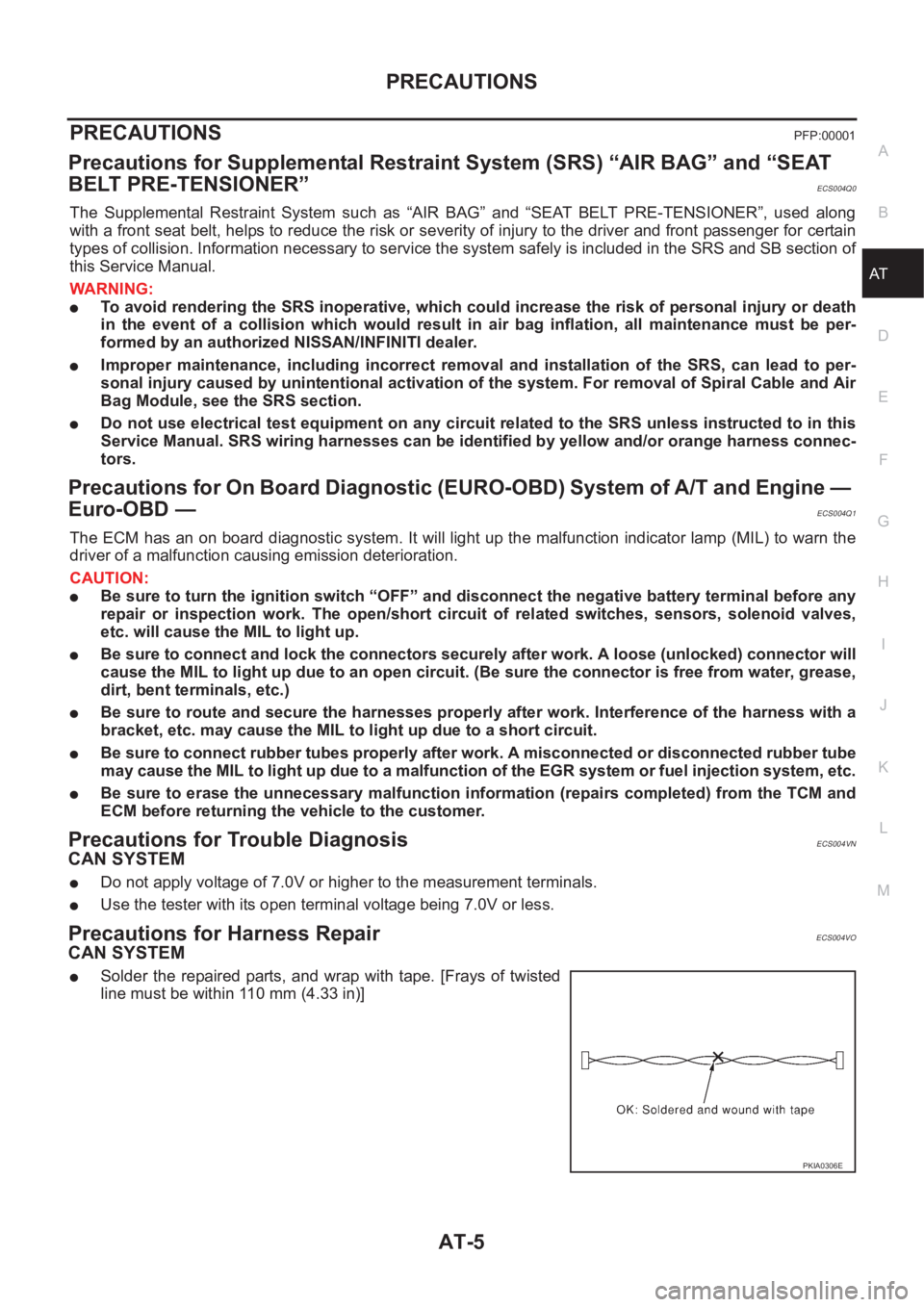
●Solder the repaired parts, and wrap with tape. [Frays of twisted
line must be within 110 mm (4.33 in)]
PKIA0306E
Page 2642 of 3833

TF-32
ALL MODE 4X4 SYSTEM
FAIL- SAFE FUNCTION
●If a malfunction occurs in 4WD electrical system, and control unit detects the malfunction, 4WD warning
lamp on gauge turns ON to inform driver of system malfunction.
●When 4WD warning lamp is ON, vehicle is in 2WD.
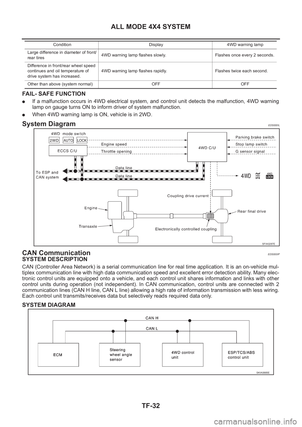
System DiagramEDS000IL
CAN CommunicationEDS000IP
SYSTEM DESCRIPTION
CAN (Controller Area Network) is a serial communication line for real time application. It is an on-vehicle mul-
tiplex communication line with high data communication speed and excellent error detection ability. Many elec-
tronic control units are equipped onto a vehicle, and each control unit shares information and links with other
control units during operation (not independent). In CAN communication, control units are connected with 2
communication lines (CAN H line, CAN L line) allowing a high rate of information transmission with less wiring.
Each control unit transmits/receives data but selectively reads required data only.
SYSTEM DIAGRAM
Large difference in diameter of front/
rear tires4WD warning lamp flashes slowly. Flashes once every 2 seconds.
Difference in front/rear wheel speed
continues and oil temperature of
drive system has increased.4WD warning lamp flashes rapidly. Flashes twice each second.
Other than above (system normal) OFF OFFCondition Display 4WD warning lamp
SFIA0287E
SKIA0885E
Page 2743 of 3833

PRECAUTIONS
BR-3
C
D
E
G
H
I
J
K
L
MA
B
BR
PRECAUTIONSPFP:00001
Precautions for Supplemental Restraint System (SRS) “AIR BAG” and “SEAT
BELT PRE-TENSIONER”
EFS002F9
The Supplemental Restraint System such as “AIR BAG” and “SEAT BELT PRE-TENSIONER”, used along
with a front seat belt, helps to reduce the risk or severity of injury to the driver and front passenger for certain
types of collision. Information necessary to service the system safely is included in the SRS and SB section of
this Service Manual.
WARNING:
●To avoid rendering the SRS inoperative, which could increase the risk of personal injury or death
in the event of a collision which would result in air bag inflation, all maintenance must be per-
formed by an authorized NISSAN/INFINITI dealer.
●Improper maintenance, including incorrect removal and installation of the SRS, can lead to per-
sonal injury caused by unintentional activation of the system. For removal of Spiral Cable and Air
Bag Module, see the SRS section.
●Do not use electrical test equipment on any circuit related to the SRS unless instructed to in this
Service Manual. SRS wiring harnesses can be identified by yellow and/or orange harness connec-
tors.
Precautions for Brake SystemEFS000BZ
●Clean dust on brake pads, shoes, drums, and back plates with a vacuum dust collector. Do not blow with
compressed air.
●Recommended fluid is brake fluid “DOT 3” or “DOT 4”.
●Never reuse drained brake fluid.
●Be careful not to splash brake fluid on painted areas such as the body. If brake fluid is splashed or spilled
on paint, wipe it off and flush the area with water immediately.
●Use only clean brake fluid when cleaning master cylinder and disc brake components.
●Never use mineral oils such as gasoline or kerosene to clean. They will ruin the rubber parts and cause
improper operation.
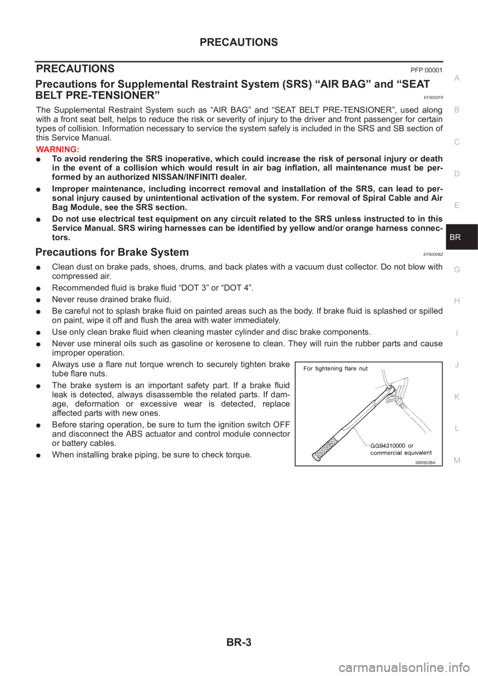
●Always use a flare nut torque wrench to securely tighten brake
tube flare nuts.
●The brake system is an important safety part. If a brake fluid
leak is detected, always disassemble the related parts. If dam-
age, deformation or excessive wear is detected, replace
affected parts with new ones.
●Before staring operation, be sure to turn the ignition switch OFF
and disconnect the ABS actuator and control module connector
or battery cables.
●When installing brake piping, be sure to check torque.SBR820BA
Page 2791 of 3833
![NISSAN X-TRAIL 2001 Service Repair Manual TROUBLE DIAGNOSIS
BRC-7
[4WD/ABS]
C
D
E
G
H
I
J
K
L
MA
B
BRC
TROUBLE DIAGNOSISPFP:00004
Fail-safe FunctionEFS001BB
●If a malfunction occurs in 4WD/ABS electrical system, and control unit NISSAN X-TRAIL 2001 Service Repair Manual TROUBLE DIAGNOSIS
BRC-7
[4WD/ABS]
C
D
E
G
H
I
J
K
L
MA
B
BRC
TROUBLE DIAGNOSISPFP:00004
Fail-safe FunctionEFS001BB
●If a malfunction occurs in 4WD/ABS electrical system, and control unit](/manual-img/5/57405/w960_57405-2790.png)
TROUBLE DIAGNOSIS
BRC-7
[4WD/ABS]
C
D
E
G
H
I
J
K
L
MA
B
BRC
TROUBLE DIAGNOSISPFP:00004
Fail-safe FunctionEFS001BB
●If a malfunction occurs in 4WD/ABS electrical system, and control unit detects the malfunction, 4WD
warning light on gauge turns ON to inform driver of system malfunction.
●When 4WD and ABS warning lamp is ON, vehicle is in 2WD.
How to Proceed with Trouble DiagnosisEFS001BC
BASIC CONCEPT
●The most important point to perform trouble diagnosis is to understand vehicle systems (control and
mechanism) thoroughly.
●It is also important to clarify customer complaints before inspec-
tion.
First of all, reproduce symptom, and understand it fully.
Ask customer about his/her complaints carefully. In some cases,
it will be necessary to check symptoms by driving vehicle with
customer.
CAUTION:
Customers are not professional. It is dangerous to make an
easy guess like “maybe the customer means that...,” or
“maybe the customer mentions this symptom”.
●It is essential to check symptoms right from the beginning in
order to repair a malfunction completely.
For intermittent malfunction, reproduce symptom based on inter-
view with customer and past examples. Do not perform inspec-
tion on ad hoc basis. Most intermittent malfunctions are caused
by poor contacts. In this case, it will be effective to shake sus-
pected harness or connector by hand. When repairing without
any symptom diagnosis, you can not judge if malfunction has
actually been eliminated.
●After completing diagnosis, always erase diagnostic memory.
Refer to BRC-24, "
Operation Procedure" .
●For intermittent malfunction, move harness or harness connector by hand. Then check poor contact or
false open circuit.
●Always read “GI General Information” to check general to confirm general precautions.
SEF234G
SEF233G
Page 2844 of 3833
![NISSAN X-TRAIL 2001 Service Repair Manual BRC-60
[ESP/TCS/ABS]
GENERAL INFORMATION
●When starting the engine, or just after starting the vehicle, the brake pedal may vibrate or the
motor operating noise may be heard from the engin NISSAN X-TRAIL 2001 Service Repair Manual BRC-60
[ESP/TCS/ABS]
GENERAL INFORMATION
●When starting the engine, or just after starting the vehicle, the brake pedal may vibrate or the
motor operating noise may be heard from the engin](/manual-img/5/57405/w960_57405-2843.png)
BRC-60
[ESP/TCS/ABS]
GENERAL INFORMATION
●When starting the engine, or just after starting the vehicle, the brake pedal may vibrate or the
motor operating noise may be heard from the engine compartment. This is a normal status of the
operation check.
●The stopping distance may be longer than that of vehicles without ABS when the vehicle drives on
rough, gravel, or snowy (fresh deep snow) road.
TCS FunctionsEFS0019V
1. With the wheel sensor signals from 4 wheels, the ESP/TCS/ABS control unit detects a wheel spin. If a
wheel spins, the control unit controls brake fluid pressure to the spinning wheel, and cuts the fuel to the
engine. It also closes the throttle valve to reduce the engine torque. Furthermore, throttle position is con-
trolled to the appropriate engine torque.
2. If a wheel spins, the TCS system works and function by applying brake fluid pressure to the spinning
wheel.
3. During TCS operation, it informs a driver of system operation by flashing SLIP indicator lamp.
CAUTION:
●During TCS operation, the body and the brake pedal lightly vibrate and the mechanical noise may
be heard. This is a normal condition.
●Depending on road circumstances, the driver may have a sluggish feel. This is not abnormal,
because the optimum traction has the highest priority by TCS operation.
●When the vehicle is passing through a road where the surface friction coefficient varies, down-
shifting or depressing the accelerator pedal fully may activate TCS temporarily.
ESP FunctionsEFS0019W
1. The Electronic Stability Program is called the ESP for short.
The ESP is indicated as the VDC (the Vehicle Dynamics Control) on the CONSULT-II screen.
2. In addition to the ABS/TCS function, ESP detects the driver's steering operation amount and brake opera-
tion amount from the steering wheel angle sensor and pressure sensor. Using the information from the
yaw rate and side G sensor and wheel sensors, ESP judges the driving condition (conditions of under-
steer and oversteer) to improve the stability by controlling the brake on 4 wheels and engine output.
3. During ESP operation, the SLIP indicator lamp flashes to inform the driver of the operation.
CAUTION:
●During ESP operation, the body and the brake pedal lightly vibrate and their mechanical noise
may be heard. This is a normal condition.
●If the vehicle is rotated on a turn table, or rolled and rocked on a ship, the ABS warning lamp,
ESP OFF indicator lamp, and SLIP indicator lamp may turn ON. In this case, start the engine on a
normal road again. If the ABS warning lamp, ESP OFF indicator lamp, and SLIP indicator lamp
turn OFF after the restart, it is normal.
●When driving in a steep slope such as a bank, the ABS warning lamp, ESP OFF indicator lamp,
and SLIP indicator lamp may turn ON. In this case, start the engine on a normal road again. If the
ABS warning lamp, ESP OFF indicator lamp, and SLIP indicator lamp turn OFF after the restart, it
is normal.
Page 2912 of 3833

PS-2
PRECAUTIONS
PRECAUTIONS
PFP:00001
Precautions for Supplemental Restraint System (SRS) “AIR BAG” and “SEAT
BELT PRE-TENSIONER”
EGS000IZ
The Supplemental Restraint System such as “AIR BAG” and “SEAT BELT PRE-TENSIONER”, used along
with a front seat belt, helps to reduce the risk or severity of injury to the driver and front passenger for certain
types of collision. Information necessary to service the system safely is included in the SRS and SB section of
this Service Manual.
WARNING:
●To avoid rendering the SRS inoperative, which could increase the risk of personal injury or death
in the event of a collision which would result in air bag inflation, all maintenance must be per-
formed by an authorized NISSAN/INFINITI dealer.
●Improper maintenance, including incorrect removal and installation of the SRS, can lead to per-
sonal injury caused by unintentional activation of the system. For removal of Spiral Cable and Air
Bag Module, see the SRS section.
●Do not use electrical test equipment on any circuit related to the SRS unless instructed to in this
Service Manual. SRS wiring harnesses can be identified by yellow and/or orange harness connec-
tors.
CautionEGS00049
●Always follow the warnings and the cautions below in disassembly procedures:
–Work in a clean, dust-free place. No dust proof device is necessary.
–Clean outside of unit before disassembly.
–Clean parts to be disassembled. Be careful not to allow any dirt or other foreign materials to enter or con-
tact with parts.
–Assemble disassembled parts properly, following order shown in manual. If work has been suspended in
the middle of assembly, place a clean cover over parts. This will prevent them from being contaminated.
–Use paper towels when removing dirt and other foreign materials. Cloth shop towels can leave lint on
cleaned parts that might affect operation of parts.
–Clean disassembled parts (except rubber parts) with kerosene. Drain oil by blowing with air or absorbing
with shop papers.
–Before assembling, apply Nissan power steering fluid to O-rings and seals.
–Replace gaskets and O-rings with new ones. Be careful not to damage any O-rings, oil seals, and gaskets
during assembly.
●If following part is scratched after disassembly of steering pump, replace applicable part: case, rear body,
side plate, pulley, rotor, vane, or flow control valve
●Mark source of fluid leak with a white marker for identification.
● Seals and copper washers must not be reused.