2001 NISSAN X-TRAIL brake sensor
[x] Cancel search: brake sensorPage 2899 of 3833
![NISSAN X-TRAIL 2001 Service Repair Manual TROUBLE DIAGNOSIS
BRC-115
[ESP/TCS/ABS]
C
D
E
G
H
I
J
K
L
MA
B
BRC
2.PEDAL FORCE INSPECTION
Check that the brake is effective with the pedal depressed.
Is the pedal heavy, but effective?
YES >> Normal NISSAN X-TRAIL 2001 Service Repair Manual TROUBLE DIAGNOSIS
BRC-115
[ESP/TCS/ABS]
C
D
E
G
H
I
J
K
L
MA
B
BRC
2.PEDAL FORCE INSPECTION
Check that the brake is effective with the pedal depressed.
Is the pedal heavy, but effective?
YES >> Normal](/manual-img/5/57405/w960_57405-2898.png)
TROUBLE DIAGNOSIS
BRC-115
[ESP/TCS/ABS]
C
D
E
G
H
I
J
K
L
MA
B
BRC
2.PEDAL FORCE INSPECTION
Check that the brake is effective with the pedal depressed.
Is the pedal heavy, but effective?
YES >> Normal
NO >> GO TO 3.
3.CONNECTOR AND PERFORMANCE INSPECTION
Disconnect the actuator relay unit connector to deactivate the ABS function. Check that the brake is effective.
Is the brake effective?
YES >> GO TO 4.
NO >> Brake line inspection
4.ABS WARNING LAMP INDICATOR INSPECTION
Check that the ABS warning lamp illuminates.
Does the ABS warning lamp illuminate?
YES >> Perform the self-diagnosis.
NO >> GO TO 5.
5.WHEEL SENSOR INSPECTION
Check the wheel sensor system.
●Sensor mounting inspection
●Sensor pick-up inspection for iron chips
●Sensor rotor inspection (e.g. Number of teeth, damaged teeth)
●Sensor connector engagement inspection
Is inspection result OK?
YES >> Normal
NO >> Wheel sensor and rotor lines repair
Symptom 3: Longer Stopping DistanceEFS001AU
Inspection procedure
1.INSPECTION START
Check that the stopping distance when braking becomes longer only on a snowy or gravel road.
Does the stopping distance when braking become longer only on a snowy or gravel road?
YES >> It may be longer than that of vehicle without ABS.
NO >> GO TO 2.
2.PERFORMANCE CHECK
Disconnect the actuator relay box to deactivate the ABS function.
Is the stopping distance still longer?
YES >>●Brake line air bleeding
●Brake line inspection
NO >> GO TO 3.
3.ABS WARNING LAMP INDICATOR INSPECTION
Check that the ABS warning lamp illuminates.
Does the ABS warning lamp illuminate?
YES >> Perform the self-diagnosis.
NO >> GO TO 4.
Page 2900 of 3833
![NISSAN X-TRAIL 2001 Service Repair Manual BRC-116
[ESP/TCS/ABS]
TROUBLE DIAGNOSIS
4. WHEEL SENSOR INSPECTION
Check the wheel sensor system.
●Sensor mounting inspection
●Sensor pick-up inspection for iron chips
●Sensor rotor inspection ( NISSAN X-TRAIL 2001 Service Repair Manual BRC-116
[ESP/TCS/ABS]
TROUBLE DIAGNOSIS
4. WHEEL SENSOR INSPECTION
Check the wheel sensor system.
●Sensor mounting inspection
●Sensor pick-up inspection for iron chips
●Sensor rotor inspection (](/manual-img/5/57405/w960_57405-2899.png)
BRC-116
[ESP/TCS/ABS]
TROUBLE DIAGNOSIS
4. WHEEL SENSOR INSPECTION
Check the wheel sensor system.
●Sensor mounting inspection
●Sensor pick-up inspection for iron chips
●Sensor rotor inspection (e.g. Number of teeth, damaged teeth)
●Sensor connector engagement inspection
Is inspection result OK?
YES >> Normal
NO >> Wheel sensor and rotor lines repair
Symptom 4: ABS Does Not Work.EFS001AV
Inspection procedure
1. ABS WARNING LAMP INDICATOR INSPECTION
Check that the ABS warning lamp illuminates.
Does the ABS warning lamp illuminate?
YES >> Perform the self-diagnosis.
NO >> GO TO 2.
2. WHEEL SENSOR INSPECTION
Check the wheel sensor system.
●Sensor mounting inspection
●Sensor pick-up inspection for iron chips
●Sensor rotor inspection (e.g. Number of teeth, damaged teeth)
●Sensor connector engagement inspection
Is inspection result OK?
YES >> Normal
NO >> Wheel sensor and rotor lines repair
Symptom 5: Pedal Vibration and NoiseEFS001AW
Inspection procedure
1. SYMPTOM CHECK
Check the brake system for pedal vibration or noise at the engine start.
Is inspection result OK?
YES >> Perform the self-diagnosis.
NO >> GO TO 2.
2. SYMPTOM CHECK 2
Check the brake system for pedal vibration or noise when the pedal depressed lightly (just put a foot on).
CAUTION:
Under the following driving conditions, the wheel speed will fluctuates, resulting in ABS activation.
●When shifting gears
●High speed cornering
●When a gust of wind
Is inspection result OK?
YES >> GO TO 3.
NO >> Normal
Page 2901 of 3833
![NISSAN X-TRAIL 2001 Service Repair Manual TROUBLE DIAGNOSIS
BRC-117
[ESP/TCS/ABS]
C
D
E
G
H
I
J
K
L
MA
B
BRC
3.SYMPTOM CHECK 3
Does the symptom appear during normal braking operation?
CAUTION:
ABS may work in following driving conditions even NISSAN X-TRAIL 2001 Service Repair Manual TROUBLE DIAGNOSIS
BRC-117
[ESP/TCS/ABS]
C
D
E
G
H
I
J
K
L
MA
B
BRC
3.SYMPTOM CHECK 3
Does the symptom appear during normal braking operation?
CAUTION:
ABS may work in following driving conditions even](/manual-img/5/57405/w960_57405-2900.png)
TROUBLE DIAGNOSIS
BRC-117
[ESP/TCS/ABS]
C
D
E
G
H
I
J
K
L
MA
B
BRC
3.SYMPTOM CHECK 3
Does the symptom appear during normal braking operation?
CAUTION:
ABS may work in following driving conditions even if there is no sudden brake.
●When road friction is low.
●High speed cornering
●When a gust of wind
Is inspection result OK?
YES >> GO TO 4.
NO >> Normal
4.SYMPTOM CHECK 4
Check that the symptom is reproduce when the engine speed is increased with the vehicle stopped.
Is inspection result OK?
YES >> GO TO 5.
NO >>
●Normal.
CAUTION:
This symptom may appear with vehicle stopped.
5.SYMPTOM CHECK 5
Check that the symptom is reproduce when any switch of electrical equipment is operated.
Is inspection result OK?
YES >> Check that there are no radio, antenna, and antenna lead-in wires (including wiring) near control
unit.
NO >> GO TO 6.
6.ABS WARNING LAMP INSPECTION
Check that the ABS warning lamp turns on.
Is inspection result OK?
YES >> Perform the self-diagnosis.
NO >> GO TO 7.
7.WHEEL SENSOR INSPECTION
Check the wheel sensor system.
●Sensor mounting inspection
●Sensor pick-up inspection for iron chips (e.g. Number of teeth, damaged teeth)
●Sensor connector engagement inspection
●Wheel sensor path harness and connector inspection
Is inspection result OK?
YES >> Normal
NO >> Wheel sensor and rotor lines repair
Symptom 6: ESP OFF Indicator Lamp Does Not IlluminateEFS001AX
Inspection procedure
1.ESP OFF INDICATOR LAMP INSPECTION
Disconnect the ESP/TCS/ABS control unit connector.
Does the ABS warning lamp and ESP OFF indicator lamp illuminate?
YES >> ESP/TCS/ABS control unit malfunction. Repair or replace the control unit.
NO >> Combination meter system malfunction. Check the combination meter.
Page 2955 of 3833
FRONT WHEEL HUB AND KNUCKLE
FAX-7
C
E
F
G
H
I
J
K
L
MA
B
FA X
FRONT WHEEL HUB AND KNUCKLEPFP:40202
On-Vehicle InspectionEDS0005R
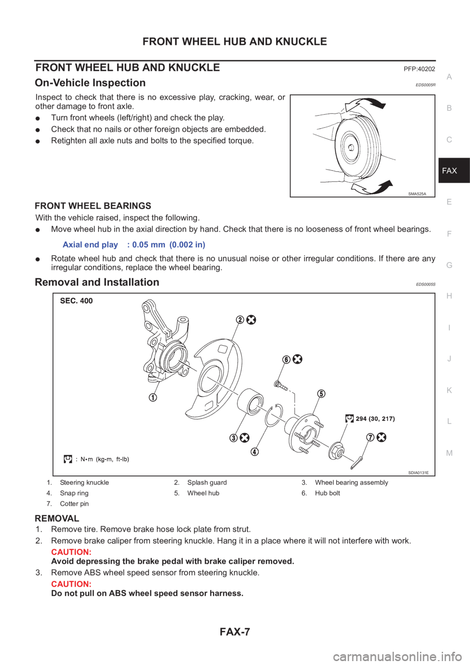
Inspect to check that there is no excessive play, cracking, wear, o r
other damage to front axle.
●Turn front wheels (left/right) and check the play.
●Check that no nails or other foreign objects are embedded.
●Retighten all axle nuts and bolts to the specified torque.
FRONT WHEEL BEARINGS
With the vehicle raised, inspect the following.
●Move wheel hub in the axial direction by hand. Check that there is no looseness of front wheel bearings.
●Rotate wheel hub and check that there is no unusual noise or other irregular conditions. If there are any
irregular conditions, replace the wheel bearing.
Removal and InstallationEDS0005S
REMOVAL
1. Remove tire. Remove brake hose lock plate from strut.
2. Remove brake caliper from steering knuckle. Hang it in a place where it will not interfere with work.
CAUTION:
Avoid depressing the brake pedal with brake caliper removed.
3. Remove ABS wheel speed sensor from steering knuckle.
CAUTION:
Do not pull on ABS wheel speed sensor harness.
SMA525A
Axial end play : 0.05 mm (0.002 in)
1. Steering knuckle 2. Splash guard 3. Wheel bearing assembly
4. Snap ring 5. Wheel hub 6. Hub bolt
7. Cotter pin
SDIA0131E
Page 2959 of 3833
FRONT DRIVE SHAFT
FAX-11
C
E
F
G
H
I
J
K
L
MA
B
FA X
FRONT DRIVE SHAFTPFP:39100
Removal and InstallationEDS0005U
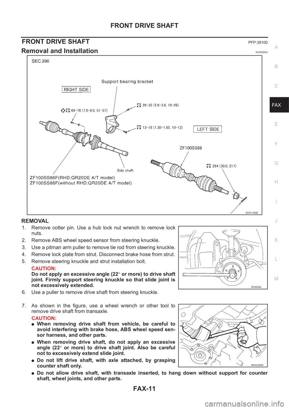
REMOVAL
1. Remove cotter pin. Use a hub lock nut wrench to remove lock
nuts.
2. Remove ABS wheel speed sensor from steering knuckle.
3. Use a pitman arm puller to remove tie rod from steering knuckle.
4. Remove lock plate from strut. Disconnect brake hose from strut.
5. Remove steering knuckle and strut installation bolt.
CAUTION:
Do not apply an excessive angle (22° or more) to drive shaft
joint. Firmly support steering knuckle so that slide joint is
not excessively extended.
6. Use a puller to remove drive shaft from steering knuckle.
7. As shown in the figure, use a wheel wrench or other tool to
remove drive shaft from transaxle.
CAUTION:
●When removing drive shaft from vehicle, be careful to
avoid interfering with brake hose, ABS wheel speed sen-
sor harness, and other parts.
●When removing drive shaft, do not apply an excessive
angle (22° or more) to drive shaft joint. Also be careful
not to excessively extend slide joint.
●Do not lift drive shaft, with axle attached, by grasping
counter shaft only.
●Do not allow drive shaft, with transaxle inserted, to hang down without support for counter
shaft, wheel joints, and other parts.
SDIA1390E
SFA649A
MAA0384D
Page 2960 of 3833
FAX-12
FRONT DRIVE SHAFT
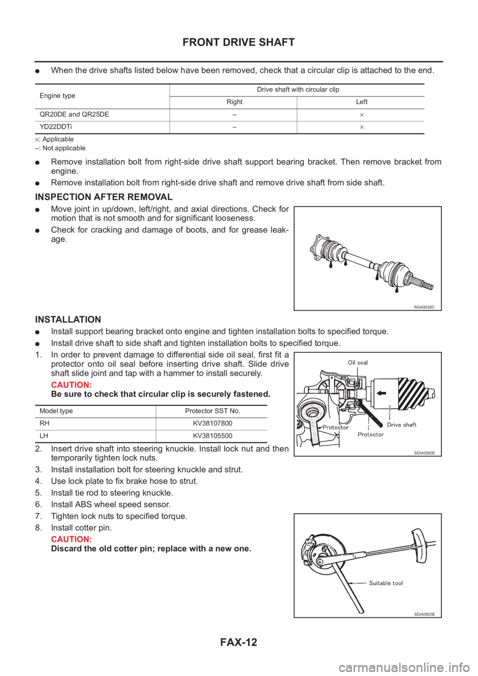
●When the drive shafts listed below have been removed, check that a circular clip is attached to the end.
×: Applicable
–: Not applicable
●Remove installation bolt from right-side drive shaft support bearing bracket. Then remove bracket from
engine.
●Remove installation bolt from right-side drive shaft and remove drive shaft from side shaft.
INSPECTION AFTER REMOVAL
●Move joint in up/down, left/right, and axial directions. Check for
motion that is not smooth and for significant looseness.
●Check for cracking and damage of boots, and for grease leak-
age.
INSTALLATION
●Install support bearing bracket onto engine and tighten installation bolts to specified torque.
●Install drive shaft to side shaft and tighten installation bolts to specified torque.
1. In order to prevent damage to differential side oil seal, first fit a
protector onto oil seal before inserting drive shaft. Slide drive
shaft slide joint and tap with a hammer to install securely.
CAUTION:
Be sure to check that circular clip is securely fastened.
2. Insert drive shaft into steering knuckle. Install lock nut and then
temporarily tighten lock nuts.
3. Install installation bolt for steering knuckle and strut.
4. Use lock plate to fix brake hose to strut.
5. Install tie rod to steering knuckle.
6. Install ABS wheel speed sensor.
7. Tighten lock nuts to specified torque.
8. Install cotter pin.
CAUTION:
Discard the old cotter pin; replace with a new one.
Engine typeDrive shaft with circular clip
Right Left
QR20DE and QR25DE –×
YD22DDTi –×
RAA0030D
Model type Protector SST No.
RH KV38107800
LH KV38105500
SDIA0593E
SDIA0603E
Page 2973 of 3833
WHEEL HUB (4WD)
RAX-7
C
E
F
G
H
I
J
K
L
MA
B
RAX
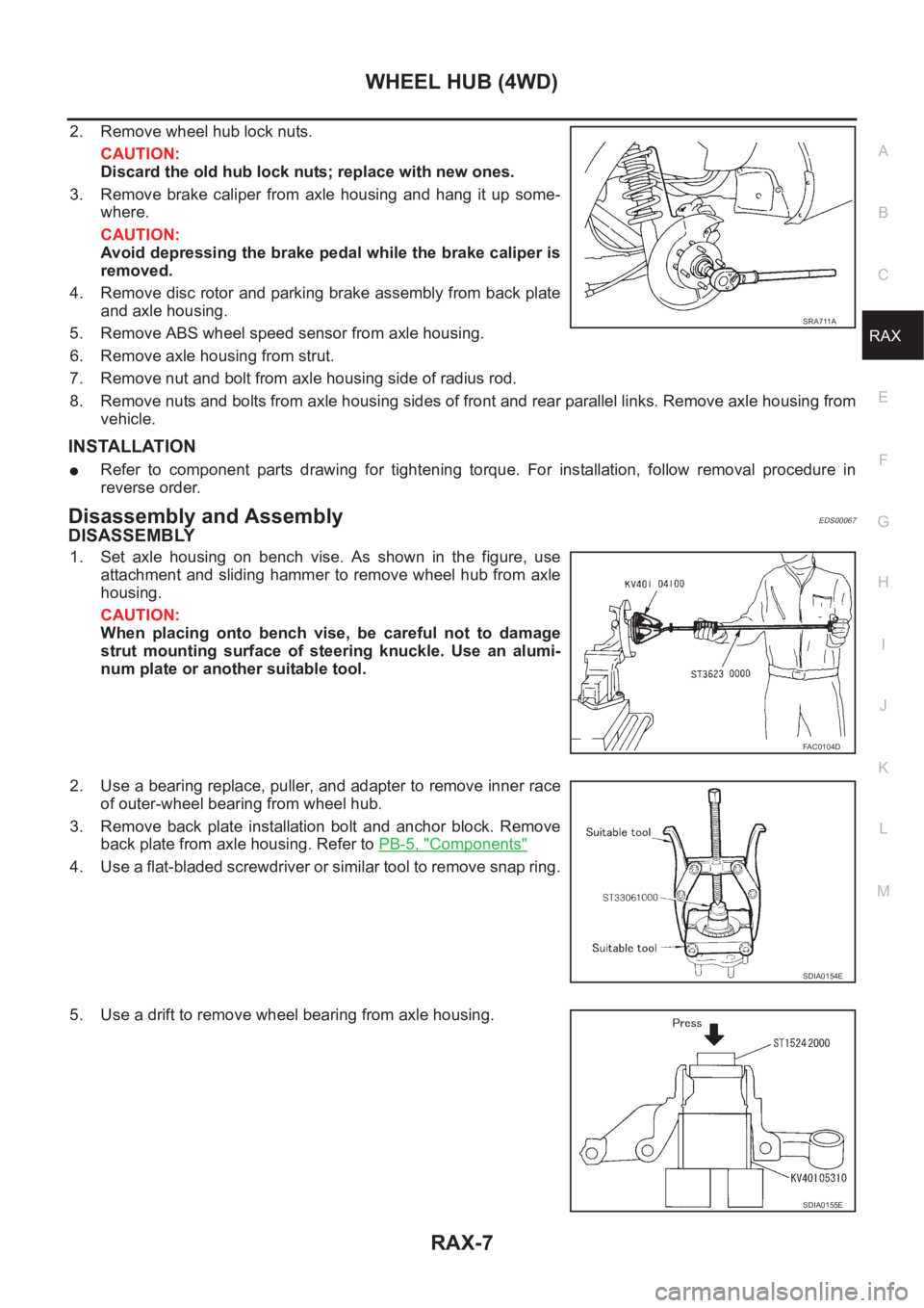
2. Remove wheel hub lock nuts.
CAUTION:
Discard the old hub lock nuts; replace with new ones.
3. Remove brake caliper from axle housing and hang it up some-
where.
CAUTION:
Avoid depressing the brake pedal while the brake caliper is
removed.
4. Remove disc rotor and parking brake assembly from back plate
and axle housing.
5. Remove ABS wheel speed sensor from axle housing.
6. Remove axle housing from strut.
7. Remove nut and bolt from axle housing side of radius rod.
8. Remove nuts and bolts from axle housing sides of front and rear parallel links. Remove axle housing from
vehicle.
INSTALLATION
●Refer to component parts drawing for tightening torque. For installation, follow removal procedure in
reverse order.
Disassembly and AssemblyEDS00067
DISASSEMBLY
1. Set axle housing on bench vise. As shown in the figure, use
attachment and sliding hammer to remove wheel hub from axle
housing.
CAUTION:
When placing onto bench vise, be careful not to damage
strut mounting surface of steering knuckle. Use an alumi-
num plate or another suitable tool.
2. Use a bearing replace, puller, and adapter to remove inner race
of outer-wheel bearing from wheel hub.
3. Remove back plate installation bolt and anchor block. Remove
back plate from axle housing. Refer to PB-5, "
Components"
4. Use a flat-bladed screwdriver or similar tool to remove snap ring.
5. Use a drift to remove wheel bearing from axle housing.
SRA711A
FAC0104D
SDIA0154E
SDIA0155E
Page 3764 of 3833
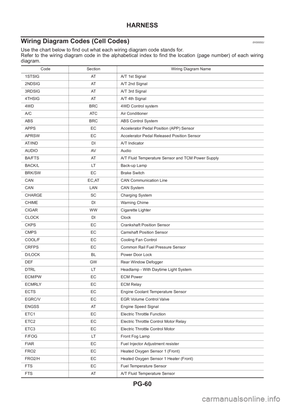
PG-60
HARNESS
Wiring Diagram Codes (Cell Codes)
EKS0032J
Use the chart below to find out what each wiring diagram code stands for.
Refer to the wiring diagram code in the alphabetical index to find the location (page number) of each wiring
diagram.
Code Section Wiring Diagram Name
1STSIG AT A/T 1st Signal
2NDSIG AT A/T 2nd Signal
3RDSIG AT A/T 3rd Signal
4THSIG AT A/T 4th Signal
4WD BRC 4WD Control system
A/C ATC Air Conditioner
ABS BRC ABS Control System
APPS EC Accelerator Pedal Position (APP) Sensor
APRSW EC Accelerator Pedal Released Position Sensor
AT/IND DI A/T Indicator
AUDIO AV Audio
BA/FTS AT A/T Fluid Temperature Sensor and TCM Power Supply
BACK/L LT Back-up Lamp
BRK/SW EC Brake Switch
CAN EC,AT CAN Communication Line
CAN LAN CAN System
CHARGE SC Charging System
CHIME DI Warning Chime
CIGAR WW Cigarette Lighter
CLOCK DI Clock
CKPS EC Crankshaft Position Sensor
CMPS EC Camshaft Position Sensor
COOL/F EC Cooling Fan Control
CRFPS EC Common Rail Fuel Pressure Sensor
D/LOCK BL Power Door Lock
DEF GW Rear Window Defogger
DTRL LT Headlamp - With Daytime Light System
ECM/PW EC ECM Power
ECMRLY EC ECM Relay
ECTS EC Engine Coolant Temperature Sensor
EGRC/V EC EGR Volume Control Valve
ENGSS AT Engine Speed Signal
ETC1 EC Electric Throttle Function
ETC2 EC Electric Throttle Control Motor Relay
ETC3 EC Electric Throttle Control Motor
F/FOG LT Front Fog Lamp
FIAR EC Fuel Injector Adjustment resister
FRO2 EC Heated Oxygen Sensor 1 (Front)
FRO2/H EC Heated Oxygen Sensor 1 Heater (Front)
FTS EC Fuel Temperature Sensor
FTS AT A/T Fluid Temperature Sensor