Page 366 of 1306
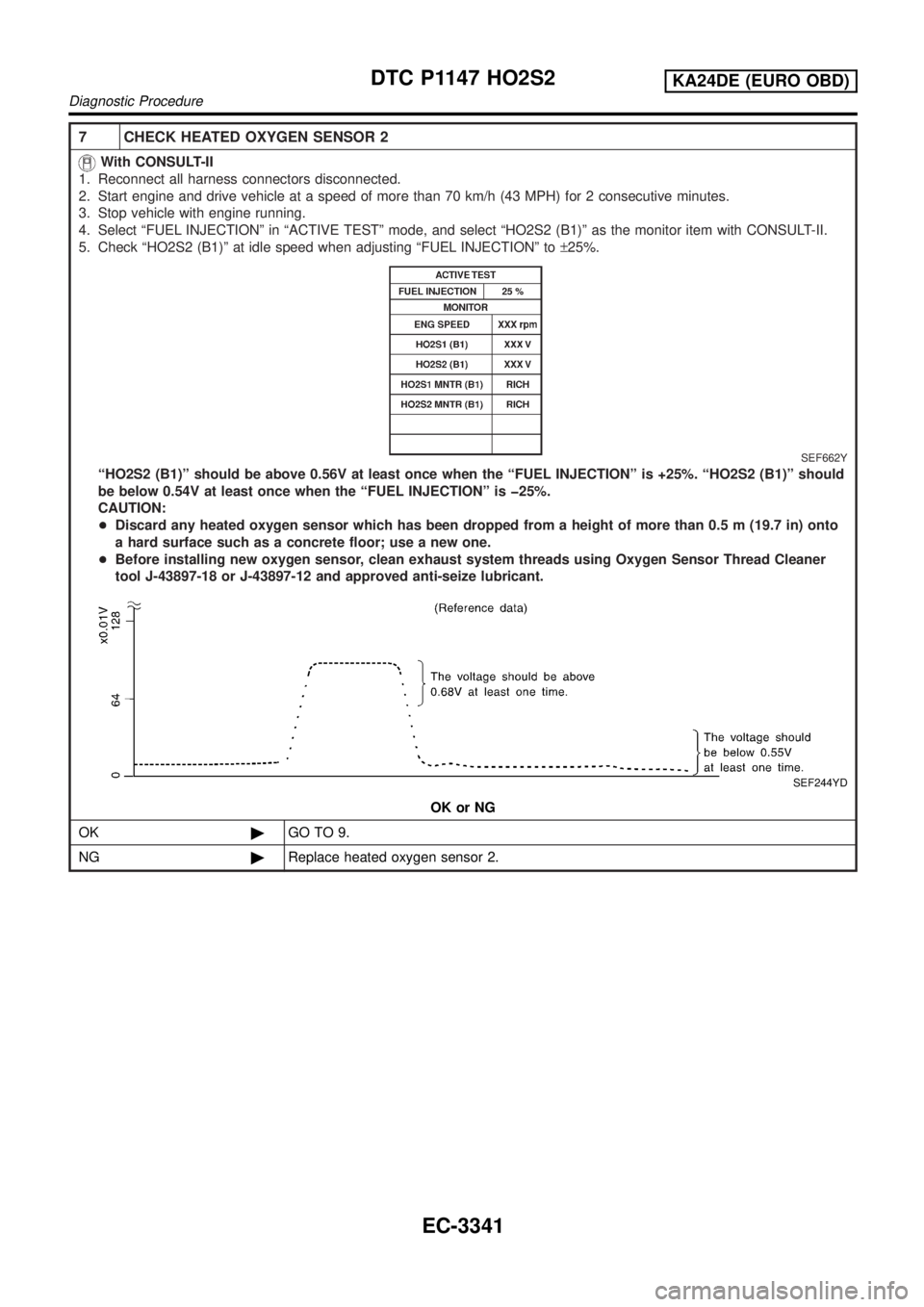
7 CHECK HEATED OXYGEN SENSOR 2
With CONSULT-II
1. Reconnect all harness connectors disconnected.
2. Start engine and drive vehicle at a speed of more than 70 km/h (43 MPH) for 2 consecutive minutes.
3. Stop vehicle with engine running.
4. Select ªFUEL INJECTIONº in ªACTIVE TESTº mode, and select ªHO2S2 (B1)º as the monitor item with CONSULT-II.
5. Check ªHO2S2 (B1)º at idle speed when adjusting ªFUEL INJECTIONº to±25%.
SEF662Y
ªHO2S2 (B1)º should be above 0.56V at least once when the ªFUEL INJECTIONº is +25%. ªHO2S2 (B1)º should
be below 0.54V at least once when the ªFUEL INJECTIONº is þ25%.
CAUTION:
+Discard any heated oxygen sensor which has been dropped from a height of more than 0.5 m (19.7 in) onto
a hard surface such as a concrete floor; use a new one.
+Before installing new oxygen sensor, clean exhaust system threads using Oxygen Sensor Thread Cleaner
tool J-43897-18 or J-43897-12 and approved anti-seize lubricant.
SEF244YD
OK or NG
OK©GO TO 9.
NG©Replace heated oxygen sensor 2.
DTC P1147 HO2S2KA24DE (EURO OBD)
Diagnostic Procedure
EC-3341
Page 367 of 1306
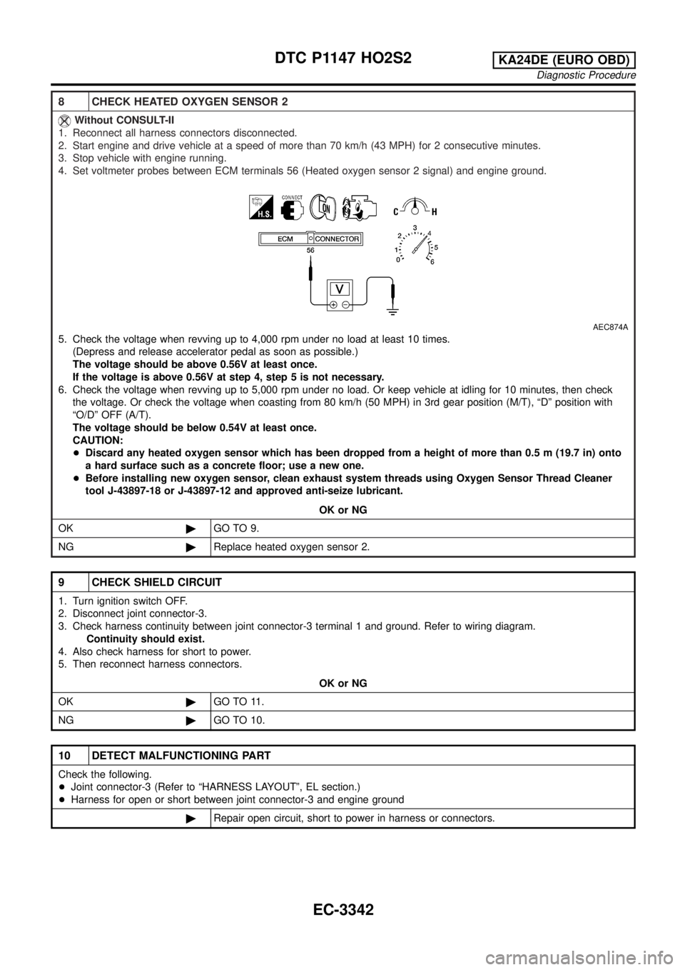
8 CHECK HEATED OXYGEN SENSOR 2
Without CONSULT-II
1. Reconnect all harness connectors disconnected.
2. Start engine and drive vehicle at a speed of more than 70 km/h (43 MPH) for 2 consecutive minutes.
3. Stop vehicle with engine running.
4. Set voltmeter probes between ECM terminals 56 (Heated oxygen sensor 2 signal) and engine ground.
AEC874A
5. Check the voltage when revving up to 4,000 rpm under no load at least 10 times.
(Depress and release accelerator pedal as soon as possible.)
The voltage should be above 0.56V at least once.
If the voltage is above 0.56V at step 4, step 5 is not necessary.
6. Check the voltage when revving up to 5,000 rpm under no load. Or keep vehicle at idling for 10 minutes, then check
the voltage. Or check the voltage when coasting from 80 km/h (50 MPH) in 3rd gear position (M/T), ªDº position with
ªO/Dº OFF (A/T).
The voltage should be below 0.54V at least once.
CAUTION:
+Discard any heated oxygen sensor which has been dropped from a height of more than 0.5 m (19.7 in) onto
a hard surface such as a concrete floor; use a new one.
+Before installing new oxygen sensor, clean exhaust system threads using Oxygen Sensor Thread Cleaner
tool J-43897-18 or J-43897-12 and approved anti-seize lubricant.
OK or NG
OK©GO TO 9.
NG©Replace heated oxygen sensor 2.
9 CHECK SHIELD CIRCUIT
1. Turn ignition switch OFF.
2. Disconnect joint connector-3.
3. Check harness continuity between joint connector-3 terminal 1 and ground. Refer to wiring diagram.
Continuity should exist.
4. Also check harness for short to power.
5. Then reconnect harness connectors.
OK or NG
OK©GO TO 11.
NG©GO TO 10.
10 DETECT MALFUNCTIONING PART
Check the following.
+Joint connector-3 (Refer to ªHARNESS LAYOUTº, EL section.)
+Harness for open or short between joint connector-3 and engine ground
©Repair open circuit, short to power in harness or connectors.
DTC P1147 HO2S2KA24DE (EURO OBD)
Diagnostic Procedure
EC-3342
Page 654 of 1306
18 CHECK GLOW PLUG
1. Remove glow plug connecting plate.
2. Check glow plug resistance.
SEC253D
NOTE:
+Do not bump glow plug heating element. If it is bumped, replace glow plug with a new one.
+If glow plug is dropped from a height of 0.1 m (3.94 in) or higher, replace with a new one.
+If glow plug installation hole is contaminated with carbon, remove it with a reamer or suitable tool.
+Hand-tighten glow plug by turning it two or three times, then tighten using a tool to specified torque.
: 1.4 - 2.2 Nzm (0.15 - 0.22 kg-m, 13 - 19 in-lb)
OK or NG
OKcGO TO 19.
NGcReplace glow plug.
19 CHECK INTERMITTENT INCIDENT
Refer to ªTROUBLE DIAGNOSIS FOR INTERMITTENT INCIDENTº, EC-3469.
cINSPECTION END
GLOW CONTROL SYSTEMYD25DDTi
Diagnostic Procedure (Cont'd)
EC-3629
Page 692 of 1306
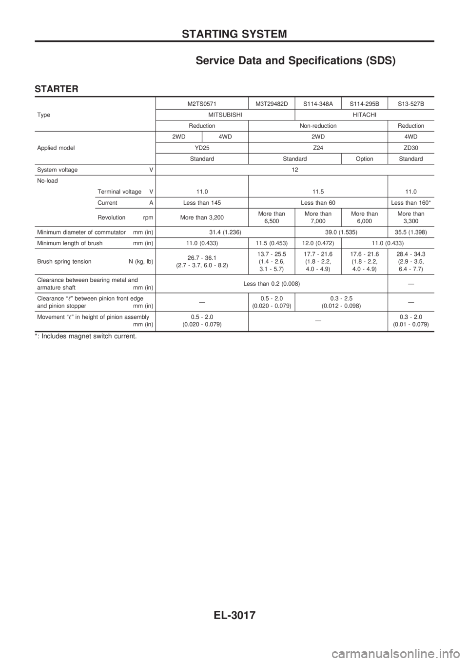
Service Data and Specifications (SDS)
STARTER
TypeM2TS0571 M3T29482D S114-348A S114-295B S13-527B
MITSUBISHI HITACHI
Reduction Non-reduction Reduction
Applied model2WD 4WD 2WD 4WD
YD25 Z24 ZD30
Standard Standard Option Standard
System voltage V 12
No-load
Terminal voltage V 11.0 11.5 11.0
Current A Less than 145 Less than 60 Less than 160*
Revolution rpm More than 3,200More than
6,500More than
7,000More than
6,000More than
3,300
Minimum diameter of commutator mm (in) 31.4 (1.236) 39.0 (1.535) 35.5 (1.398)
Minimum length of brush mm (in) 11.0 (0.433) 11.5 (0.453) 12.0 (0.472) 11.0 (0.433)
Brush spring tension N (kg, lb)26.7 - 36.1
(2.7 - 3.7, 6.0 - 8.2)13.7 - 25.5
(1.4 - 2.6,
3.1 - 5.7)17.7 - 21.6
(1.8 - 2.2,
4.0 - 4.9)17.6 - 21.6
(1.8 - 2.2,
4.0 - 4.9)28.4 - 34.3
(2.9 - 3.5,
6.4 - 7.7)
Clearance between bearing metal and
armature shaft mm (in)Less than 0.2 (0.008) Ð
Clearance ª!º between pinion front edge
and pinion stopper mm (in)Ð0.5 - 2.0
(0.020 - 0.079)0.3 - 2.5
(0.012 - 0.098)Ð
Movement ª!º in height of pinion assembly
mm (in)0.5 - 2.0
(0.020 - 0.079)Ð0.3 - 2.0
(0.01 - 0.079)
*: Includes magnet switch current.
STARTING SYSTEM
EL-3017
Page 927 of 1306
Amount of cylinder block resurfacing is ªBº.
The maximum limit:A+B=0.07 mm (0.0028 in)
After resurfacing cylinder head, check that camshaft rotates
freely by hand. If resistance is felt, cylinder head must be
replaced.
Nominal cylinder head height:
153.9 - 154.1 mm (6.059 - 6.067 in)
CAMSHAFT VISUAL CHECK
Check camshaft for scratches, seizure and wear.
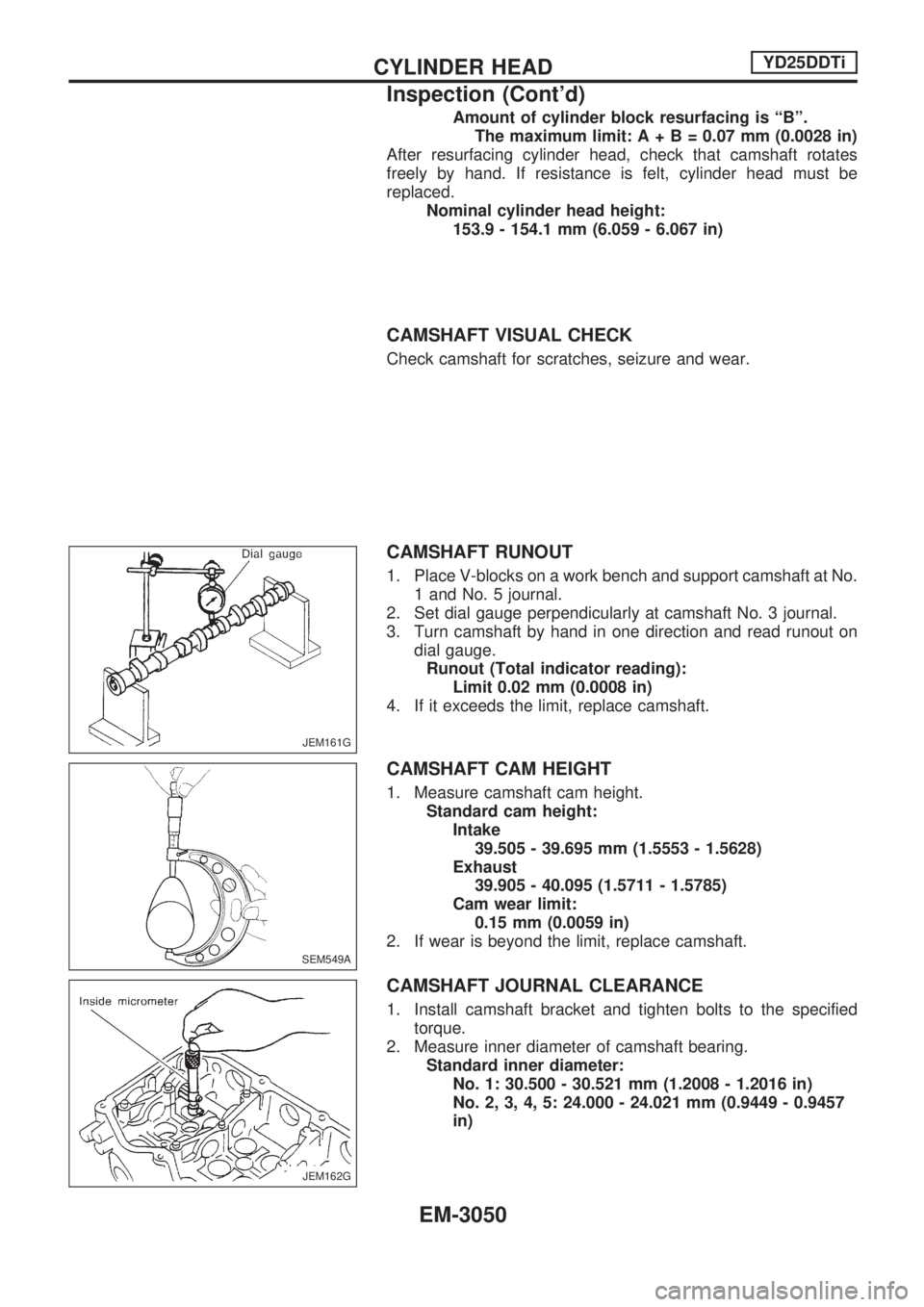
CAMSHAFT RUNOUT
1. Place V-blocks on a work bench and support camshaft at No.
1 and No. 5 journal.
2. Set dial gauge perpendicularly at camshaft No. 3 journal.
3. Turn camshaft by hand in one direction and read runout on
dial gauge.
Runout (Total indicator reading):
Limit 0.02 mm (0.0008 in)
4. If it exceeds the limit, replace camshaft.
CAMSHAFT CAM HEIGHT
1. Measure camshaft cam height.
Standard cam height:
Intake
39.505 - 39.695 mm (1.5553 - 1.5628)
Exhaust
39.905 - 40.095 (1.5711 - 1.5785)
Cam wear limit:
0.15 mm (0.0059 in)
2. If wear is beyond the limit, replace camshaft.
CAMSHAFT JOURNAL CLEARANCE
1. Install camshaft bracket and tighten bolts to the specified
torque.
2. Measure inner diameter of camshaft bearing.
Standard inner diameter:
No. 1: 30.500 - 30.521 mm (1.2008 - 1.2016 in)
No. 2, 3, 4, 5: 24.000 - 24.021 mm (0.9449 - 0.9457
in)
JEM161G
SEM549A
JEM162G
CYLINDER HEADYD25DDTi
Inspection (Cont'd)
EM-3050
Page 932 of 1306
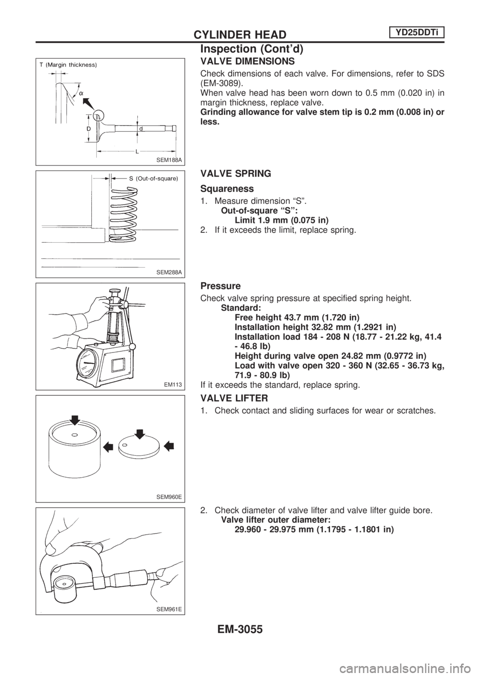
VALVE DIMENSIONS
Check dimensions of each valve. For dimensions, refer to SDS
(EM-3089).
When valve head has been worn down to 0.5 mm (0.020 in) in
margin thickness, replace valve.
Grinding allowance for valve stem tip is 0.2 mm (0.008 in) or
less.
VALVE SPRING
Squareness
1. Measure dimension ªSº.
Out-of-square ªSº:
Limit 1.9 mm (0.075 in)
2. If it exceeds the limit, replace spring.
Pressure
Check valve spring pressure at specified spring height.
Standard:
Free height 43.7 mm (1.720 in)
Installation height 32.82 mm (1.2921 in)
Installation load 184 - 208 N (18.77 - 21.22 kg, 41.4
- 46.8 lb)
Height during valve open 24.82 mm (0.9772 in)
Load with valve open 320 - 360 N (32.65 - 36.73 kg,
71.9 - 80.9 lb)
If it exceeds the standard, replace spring.
VALVE LIFTER
1. Check contact and sliding surfaces for wear or scratches.
2. Check diameter of valve lifter and valve lifter guide bore.
Valve lifter outer diameter:
29.960 - 29.975 mm (1.1795 - 1.1801 in)
SEM188A
SEM288A
EM113
SEM960E
SEM961E
CYLINDER HEADYD25DDTi
Inspection (Cont'd)
EM-3055
Page 949 of 1306
Refer to SDS (EM-3094).
+When replacing the piston, check the cylinder block surface
for scratches or seizure. If scratches or seizure is found,
hone or replace the cylinder block.
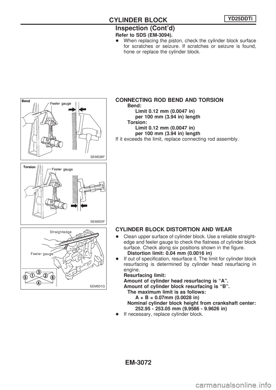
CONNECTING ROD BEND AND TORSION
Bend:
Limit 0.12 mm (0.0047 in)
per 100 mm (3.94 in) length
Torsion:
Limit 0.12 mm (0.0047 in)
per 100 mm (3.94 in) length
If it exceeds the limit, replace connecting rod assembly.
CYLINDER BLOCK DISTORTION AND WEAR
+Clean upper surface of cylinder block. Use a reliable straight-
edge and feeler gauge to check the flatness of cylinder block
surface. Check along six positions shown in the figure.
Distortion limit: 0.04 mm (0.0016 in)
+If out of specification, resurface it. The limit for cylinder block
resurfacing is determined by cylinder head resurfacing in
engine.
Resurfacing limit:
Amount of cylinder head resurfacing is ªAº.
Amount of cylinder block resurfacing is ªBº.
The maximum limit is as follows:
A+B=0.07mm (0.0028 in)
Nominal cylinder block height from crankshaft center:
252.95 - 253.05 mm (9.9586 - 9.9626 in)
+If necessary, replace cylinder block.
SEM038F
SEM003F
SEM501G
CYLINDER BLOCKYD25DDTi
Inspection (Cont'd)
EM-3072
Page 956 of 1306
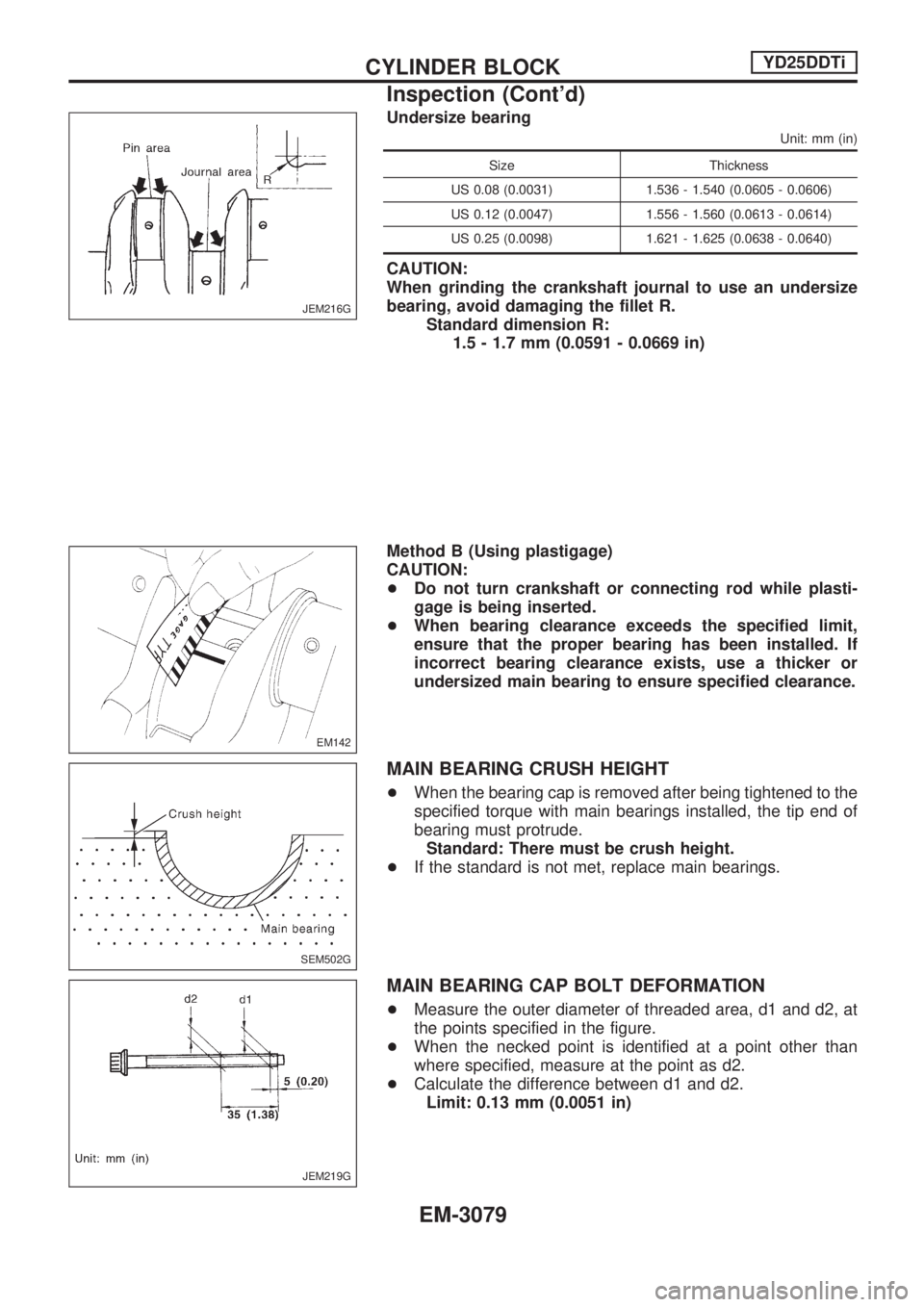
Undersize bearing
Unit: mm (in)
Size Thickness
US 0.08 (0.0031) 1.536 - 1.540 (0.0605 - 0.0606)
US 0.12 (0.0047) 1.556 - 1.560 (0.0613 - 0.0614)
US 0.25 (0.0098) 1.621 - 1.625 (0.0638 - 0.0640)
CAUTION:
When grinding the crankshaft journal to use an undersize
bearing, avoid damaging the fillet R.
Standard dimension R:
1.5 - 1.7 mm (0.0591 - 0.0669 in)
Method B (Using plastigage)
CAUTION:
+Do not turn crankshaft or connecting rod while plasti-
gage is being inserted.
+When bearing clearance exceeds the specified limit,
ensure that the proper bearing has been installed. If
incorrect bearing clearance exists, use a thicker or
undersized main bearing to ensure specified clearance.
MAIN BEARING CRUSH HEIGHT
+When the bearing cap is removed after being tightened to the
specified torque with main bearings installed, the tip end of
bearing must protrude.
Standard: There must be crush height.
+If the standard is not met, replace main bearings.
MAIN BEARING CAP BOLT DEFORMATION
+Measure the outer diameter of threaded area, d1 and d2, at
the points specified in the figure.
+When the necked point is identified at a point other than
where specified, measure at the point as d2.
+Calculate the difference between d1 and d2.
Limit: 0.13 mm (0.0051 in)
JEM216G
EM142
SEM502G
JEM219G
CYLINDER BLOCKYD25DDTi
Inspection (Cont'd)
EM-3079