Page 27 of 273

Body Front End
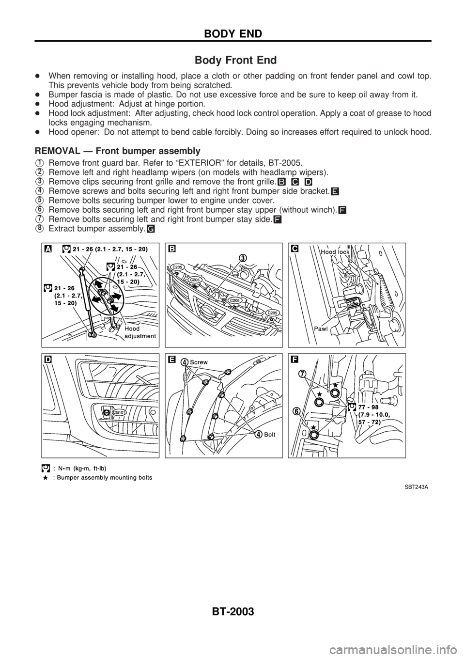
+When removing or installing hood, place a cloth or other padding on front fender panel and cowl top.
This prevents vehicle body from being scratched.
+Bumper fascia is made of plastic. Do not use excessive force and be sure to keep oil away from it.
+Hood adjustment: Adjust at hinge portion.
+Hood lock adjustment: After adjusting, check hood lock control operation. Apply a coat of grease to hood
locks engaging mechanism.
+Hood opener: Do not attempt to bend cable forcibly. Doing so increases effort required to unlock hood.
REMOVAL Ð Front bumper assembly
V1Remove front guard bar. Refer to ªEXTERIORº for details, BT-2005.
V2Remove left and right headlamp wipers (on models with headlamp wipers).
V3Remove clips securing front grille and remove the front grille.
V4Remove screws and bolts securing left and right front bumper side bracket.
V5Remove bolts securing bumper lower to engine under cover.
V6Remove bolts securing left and right front bumper stay upper (without winch).
V7Remove bolts securing left and right front bumper stay side.
V8Extract bumper assembly.
SBT243A
BODY END
BT-2003
Page 261 of 273

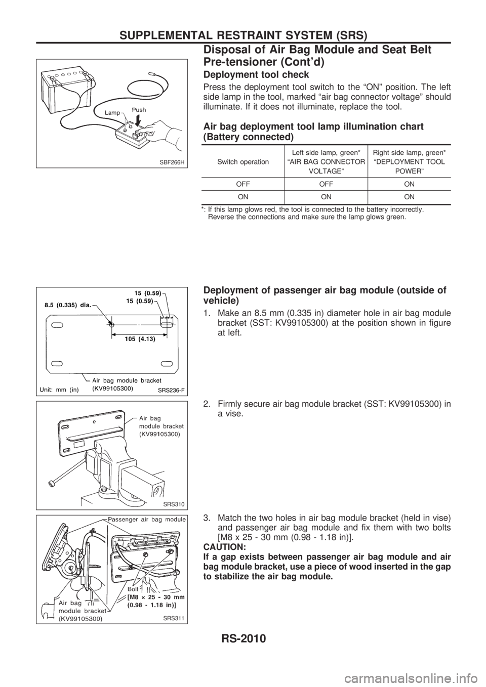
Deployment tool check
Press the deployment tool switch to the ªONº position. The left
side lamp in the tool, marked ªair bag connector voltageº should
illuminate. If it does not illuminate, replace the tool.
Air bag deployment tool lamp illumination chart
(Battery connected)
Switch operationLeft side lamp, green*
ªAIR BAG CONNECTOR
VOLTAGEºRight side lamp, green*
ªDEPLOYMENT TOOL
POWERº
OFF OFF ON
ON ON ON
*: If this lamp glows red, the tool is connected to the battery incorrectly.
Reverse the connections and make sure the lamp glows green.
Deployment of passenger air bag module (outside of
vehicle)
1. Make an 8.5 mm (0.335 in) diameter hole in air bag module
bracket (SST: KV99105300) at the position shown in figure
at left.
2. Firmly secure air bag module bracket (SST: KV99105300) in
a vise.
3. Match the two holes in air bag module bracket (held in vise)
and passenger air bag module and fix them with two bolts
[M8 x 25 - 30 mm (0.98 - 1.18 in)].
CAUTION:
If a gap exists between passenger air bag module and air
bag module bracket, use a piece of wood inserted in the gap
to stabilize the air bag module.
SBF266H
SRS236-F
SRS310
SRS311
SUPPLEMENTAL RESTRAINT SYSTEM (SRS)
Disposal of Air Bag Module and Seat Belt
Pre-tensioner (Cont'd)
RS-2010
Page 265 of 273

Trouble Diagnoses Introduction
CAUTION:
+Do not use electrical test equipment to check SRS harness connectors unless instructed to in
this Service Manual. SRS wiring harnesses can be identified by yellow harness connector.
+Do not attempt to repair, splice or modify the SRS wiring harness. If the harness is damaged,
replace it with a new one.
+Keep ground portion clean.
DIAGNOSIS FUNCTION
The SRS self-diagnosis results can be read by using ªAIR BAGº warning lamp and/or CONSULT-II. The
reading of these results is accomplished using one of two modes Ð ªUser modeº and ªDiagnosis modeº.
The User mode is exclusively prepared for the customer (driver). This mode warns the driver of a system
malfunction through the operation of the ªAIR BAGº warning lamp.
The Diagnosis mode allows the technician to locate and inspect the malfunctioning part.
The mode applications for the ªAIR BAGº warning lamp and CONSULT-II are as follows:
User mode Diagnosis mode Display type
ªAIR BAGº warning lamp X X ON-OFF operation
CONSULT-II Ð X Monitoring
DIAGNOSIS MODE FOR CONSULT-II
+ªSELF-DIAG [CURRENT]º
A current Self-diagnosis result (also indicated by the warning lamp flashes in the Diagnosis mode) is
displayed on the CONSULT-II screen in real time. This refers to a malfunctioning part requiring repairs.
+ªSELF-DIAG [PAST]º
Diagnosis results previously stored in the memory are displayed on the CONSULT-II screen. The stored
results are not erased until memory erasing is executed.
+ªTROUBLE DIAG RECORDº
With TROUBLE DIAG RECORD, diagnosis results previously erased by a reset operation can be dis-
played on the CONSULT-II screen.
+ªECU DISCRIMINATED NO.º
The diagnosis sensor unit for each vehicle model is assigned with its own, individual classification number.
This number will be displayed on the CONSULT-II screen, as shown at left. When replacing the diagnosis
sensor unit, refer to the part number for the compatibility. After installation, replacement with a correct unit
can be checked by confirming this classification number on the CONSULT-II screen. The diagnosis sensor
unit classification number varies depending on SRS configuration.
For NISSAN MODEL Y61, the diagnosis sensor unit classification numbers are as follows.
MODEL ECU DISCRIMINATED NO.
Model with dual air bags, side air bag and seat belt pre-tensioner 5A35
Model with dual air bags and side air bag 5A34
Model with dual air bags and seat belt pre-tensioner 5A33
Model with dual air bag5A32
Model with single air bag and pre-tensioner 5A31
Model with single air bag5A30
TROUBLE DIAGNOSES Ð Supplemental Restraint System (SRS)
RS-2014