2001 NISSAN PATROL warning
[x] Cancel search: warningPage 253 of 273
Supplemental Restraint System (SRS) ªAIR
BAGº and ªSEAT BELT PRE-TENSIONERº
The Supplemental Restraint System such as ªAIR BAGº and ªSEAT BELT PRE-TENSIONERº used along
with a seat belt, helps to reduce the risk or severity of injury to the driver and front passenger for certain
types of collision. The SRS composition which is available to NISSAN MODEL Y61 is as follows (The com-
position varies according to the destination and optional equipment.):
+For a frontal collision
The Supplemental Restraint System consists of driver air bag module (located in the center of the
steering wheel), front passenger air bag module (located on the instrument panel on passenger side),
seat belt pre-tensioners, a diagnosis sensor unit, warning lamp, wiring harness and spiral cable.
+For a side collision
The Supplemental Restraint System consists of front side air bag module (located in the outer side of
front seat), satellite sensor, diagnosis sensor unit (one of components of air bags for a frontal collision),
wiring harness, warning lamp (one of components of air bags for a frontal collision).
WARNING:
+To avoid rendering the SRS inoperative, which could increase the risk of personal injury or death
in the event of a collision which would result in air bag inflation, all maintenance should be per-
formed by an authorized NISSAN dealer.
+Improper maintenance, including incorrect removal and installation of the SRS, can lead to per-
sonal injury caused by unintentional activation of the system.
+Do not use electrical test equipment on any circuit related to the SRS unless instructed to in this
Service Manual. SRS wiring harnesses can be identified by yellow harness connector.
PRECAUTION
RS-2002
Page 259 of 273
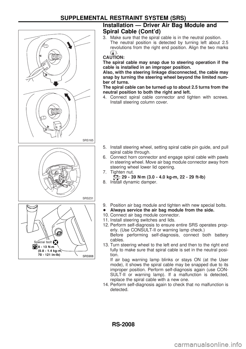
3. Make sure that the spiral cable is in the neutral position.
The neutral position is detected by turning left about 2.5
revolutions from the right end position. Align the two marks
(
,
m).
CAUTION:
The spiral cable may snap due to steering operation if the
cable is installed in an improper position.
Also, with the steering linkage disconnected, the cable may
snap by turning the steering wheel beyond the limited num-
ber of turns.
The spiral cable can be turned up to about 2.5 turns from the
neutral position to both the right and left.
4. Connect spiral cable connector and tighten with screws.
Install steering column cover.
5. Install steering wheel, setting spiral cable pin guide, and pull
spiral cable through.
6. Connect horn connector and engage spiral cable with pawls
in steering wheel. Move air bag module connector away from
steering wheel lower lid opening.
7. Tighten nut.
:29-39Nzm (3.0 - 4.0 kg-m, 22 - 29 ft-lb)
8. Install dynamic damper.
9. Position air bag module and tighten with new special bolts.
+Always service the air bag module from the side.
10. Connect air bag module connector.
11. Install steering switches and lids.
12. Perform self-diagnosis to ensure entire SRS operates prop-
erly. (Use CONSULT-II or warning lamp check.)
Before performing self-diagnosis, connect both battery
cables.
13. Turn steering wheel to the left end and then to the right end
fully to make sure that spiral cable is set in the neutral posi-
tion.
If air bag warning lamp blinks or stays ON (at the User
mode), it shows the spiral cable may be snapped due to its
improper position. Perform self-diagnosis again (use CON-
SULT-II or warning lamp). If a malfunction is detected,
replace the spiral cable with a new one.
14. Perform self-diagnosis again to check that no malfunction is
detected.
SRS165
SRS231
SRS908
SUPPLEMENTAL RESTRAINT SYSTEM (SRS)
Installation Ð Driver Air Bag Module and
Spiral Cable (Cont'd)
RS-2008
Page 265 of 273
Trouble Diagnoses Introduction
CAUTION:
+Do not use electrical test equipment to check SRS harness connectors unless instructed to in
this Service Manual. SRS wiring harnesses can be identified by yellow harness connector.
+Do not attempt to repair, splice or modify the SRS wiring harness. If the harness is damaged,
replace it with a new one.
+Keep ground portion clean.
DIAGNOSIS FUNCTION
The SRS self-diagnosis results can be read by using ªAIR BAGº warning lamp and/or CONSULT-II. The
reading of these results is accomplished using one of two modes Ð ªUser modeº and ªDiagnosis modeº.
The User mode is exclusively prepared for the customer (driver). This mode warns the driver of a system
malfunction through the operation of the ªAIR BAGº warning lamp.
The Diagnosis mode allows the technician to locate and inspect the malfunctioning part.
The mode applications for the ªAIR BAGº warning lamp and CONSULT-II are as follows:
User mode Diagnosis mode Display type
ªAIR BAGº warning lamp X X ON-OFF operation
CONSULT-II Ð X Monitoring
DIAGNOSIS MODE FOR CONSULT-II
+ªSELF-DIAG [CURRENT]º
A current Self-diagnosis result (also indicated by the warning lamp flashes in the Diagnosis mode) is
displayed on the CONSULT-II screen in real time. This refers to a malfunctioning part requiring repairs.
+ªSELF-DIAG [PAST]º
Diagnosis results previously stored in the memory are displayed on the CONSULT-II screen. The stored
results are not erased until memory erasing is executed.
+ªTROUBLE DIAG RECORDº
With TROUBLE DIAG RECORD, diagnosis results previously erased by a reset operation can be dis-
played on the CONSULT-II screen.
+ªECU DISCRIMINATED NO.º
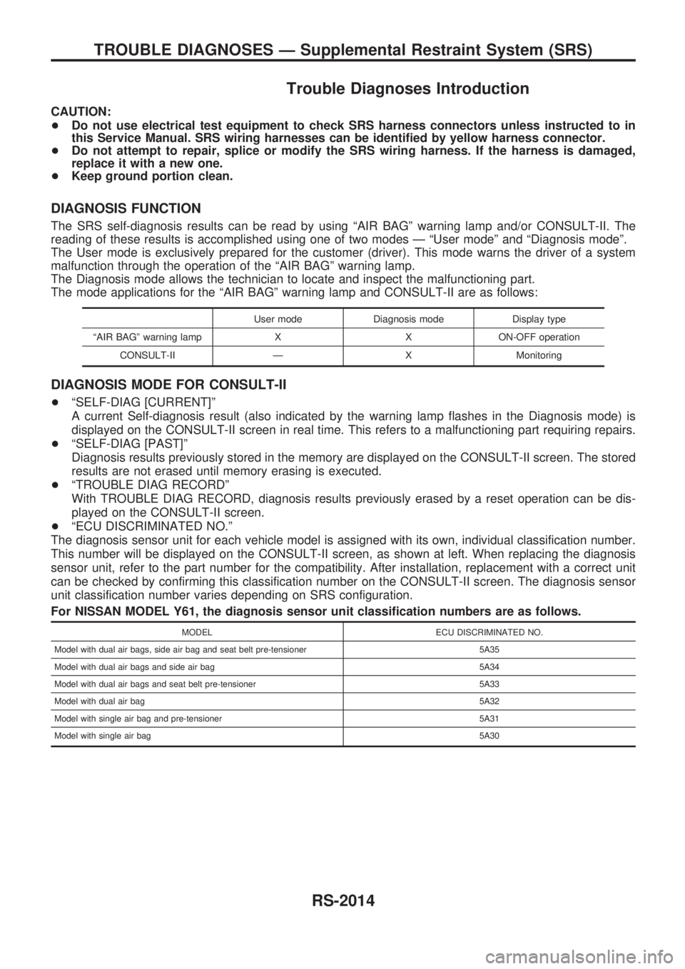
The diagnosis sensor unit for each vehicle model is assigned with its own, individual classification number.
This number will be displayed on the CONSULT-II screen, as shown at left. When replacing the diagnosis
sensor unit, refer to the part number for the compatibility. After installation, replacement with a correct unit
can be checked by confirming this classification number on the CONSULT-II screen. The diagnosis sensor
unit classification number varies depending on SRS configuration.
For NISSAN MODEL Y61, the diagnosis sensor unit classification numbers are as follows.
MODEL ECU DISCRIMINATED NO.
Model with dual air bags, side air bag and seat belt pre-tensioner 5A35
Model with dual air bags and side air bag 5A34
Model with dual air bags and seat belt pre-tensioner 5A33
Model with dual air bag5A32
Model with single air bag and pre-tensioner 5A31
Model with single air bag5A30
TROUBLE DIAGNOSES Ð Supplemental Restraint System (SRS)
RS-2014
Page 267 of 273
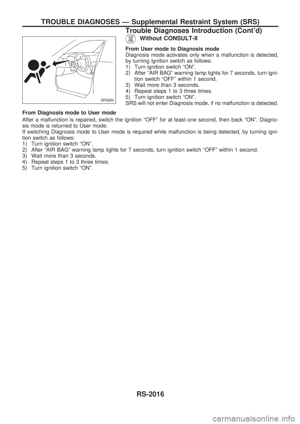
Without CONSULT-II
From User mode to Diagnosis mode
Diagnosis mode activates only when a malfunction is detected,
by turning ignition switch as follows:
1) Turn ignition switch ªONº.
2) After ªAIR BAGº warning lamp lights for 7 seconds, turn igni-
tion switch ªOFFº within 1 second.
3) Wait more than 3 seconds.
4) Repeat steps 1 to 3 three times.
5) Turn ignition switch ªONº.
SRS will not enter Diagnosis mode, if no malfunction is detected.
From Diagnosis mode to User mode
After a malfunction is repaired, switch the ignition ªOFFº for at least one second, then back ªONº. Diagno-
sis mode is returned to User mode.
If switching Diagnosis mode to User mode is required while malfunction is being detected, by turning igni-
tion switch as follows:
1) Turn ignition switch ªONº.
2) After ªAIR BAGº warning lamp lights for 7 seconds, turn ignition switch ªOFFº within 1 second.
3) Wait more than 3 seconds.
4) Repeat steps 1 to 3 three times.
5) Turn ignition switch ªONº.
SRS800
TROUBLE DIAGNOSES Ð Supplemental Restraint System (SRS)
Trouble Diagnoses Introduction (Cont'd)
RS-2016
Page 268 of 273
![NISSAN PATROL 2001 Electronic Repair Manual HOW TO ERASE SELF-DIAGNOSIS RESULTS
With CONSULT-II
+ªSELF-DIAG [CURRENT]º
A current Self-diagnosis result is displayed on the CON-
SULT-II screen in real time. After the malfunction is repaired
com NISSAN PATROL 2001 Electronic Repair Manual HOW TO ERASE SELF-DIAGNOSIS RESULTS
With CONSULT-II
+ªSELF-DIAG [CURRENT]º
A current Self-diagnosis result is displayed on the CON-
SULT-II screen in real time. After the malfunction is repaired
com](/manual-img/5/57366/w960_57366-267.png)
HOW TO ERASE SELF-DIAGNOSIS RESULTS
With CONSULT-II
+ªSELF-DIAG [CURRENT]º
A current Self-diagnosis result is displayed on the CON-
SULT-II screen in real time. After the malfunction is repaired
completely, no malfunction is detected on ªSELF-DIAG
[CURRENT]º.
+ªSELF-DIAG [PAST]º
Return to the ªSELF-DIAG [CURRENT]º CONSULT-II screen
by pushing ªBACKº key of CONSULT-II and select ªSELF-
DIAG [CURRENT]º in ªSELECT DIAG MODEº. Touch
ªERASEº in ªSELF-DIAG [CURRENT]º mode.
NOTE:
If the memory of the malfunction in ªSELF-DIAG [PAST]º is
not erased, the User mode shows the system malfunction by
the operation of the warning lamp even if the malfunction is
repaired completely.
+ªTROUBLE DIAG RECORDº
The memory of ªTROUBLE DIAG RECORDº cannot be
erased.
Without CONSULT-II
After a malfunction is repaired, return Diagnosis mode to User
mode by switching the ignition ªOFFº for at least 1 second, then
back ªONº. At that time, the self-diagnostic result is cleared.
How to Perform Trouble Diagnoses for Quick
and Accurate Repair
A good understanding of the malfunction conditions can make troubleshooting faster and more accurate.
In general, each customer feels differently about a malfunction. It is important to fully understand the symp-
toms or conditions for a customer complaint.
INFORMATION FROM CUSTOMER
WHAT ........ Vehicle model
WHEN ....... Date, Frequencies
WHERE ..... Road conditions
HOW .......... Operating conditions, Symptoms
PRELIMINARY CHECK
Check that the following parts are in good order.
+Battery [Refer to EL section (ªBATTERYº) of Service Manual.]
+Fuse [Refer to EL section (ªFuseº, ªPOWER SUPPLY ROUTINGº) of Service Manual.]
+System component-to-harness connections
SRS701
TROUBLE DIAGNOSES Ð Supplemental Restraint System (SRS)
Trouble Diagnoses Introduction (Cont'd)
RS-2017
Page 269 of 273
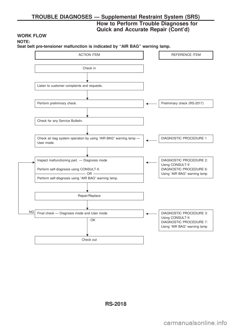
WORK FLOW
NOTE:
Seat belt pre-tensioner malfunction is indicated by ªAIR BAGº warning lamp.
ACTION ITEMREFERENCE ITEM
Check in
Listen to customer complaints and requests.
Perform preliminary check.bPreliminary check (RS-2017)
Check for any Service Bulletin.
Check air bag system operation by using ªAIR BAGº warning lamp Ð
User mode.bDIAGNOSTIC PROCEDURE 1
cInspect malfunctioning part. Ð Diagnosis mode
Perform self-diagnosis using CONSULT-II.
----------------------------------------------------------------------------------------------------------------------------------------------------------------------------------------------------------------------------------OR ----------------------------------------------------------------------------------------------------------------------------------------------------------------------------------------------------------------------------------
Perform self-diagnosis using ªAIR BAGº warning lamp.bDIAGNOSTIC PROCEDURE 2:
Using CONSULT-II
DIAGNOSTIC PROCEDURE 6:
Using ªAIR BAGº warning lamp
Repair/Replace
NGFinal check Ð Diagnosis mode and User mode
OK
bDIAGNOSTIC PROCEDURE 3:
Using CONSULT-II
DIAGNOSTIC PROCEDURE 7:
Using ªAIR BAGº warning lamp
Check out
.
.
.
.
.
.
.
.
TROUBLE DIAGNOSES Ð Supplemental Restraint System (SRS)
How to Perform Trouble Diagnoses for
Quick and Accurate Repair (Cont'd)
RS-2018