2001 NISSAN PATROL warning
[x] Cancel search: warningPage 152 of 273

TEL431M
WARNING LAMPS/WAGON AND HARDTOP MODELS
Wiring Diagram Ð WARN Ð (Cont'd)
EL-2075
Page 153 of 273

TEL432M
WARNING LAMPS/WAGON AND HARDTOP MODELS
Wiring Diagram Ð WARN Ð (Cont'd)
EL-2076
Page 154 of 273
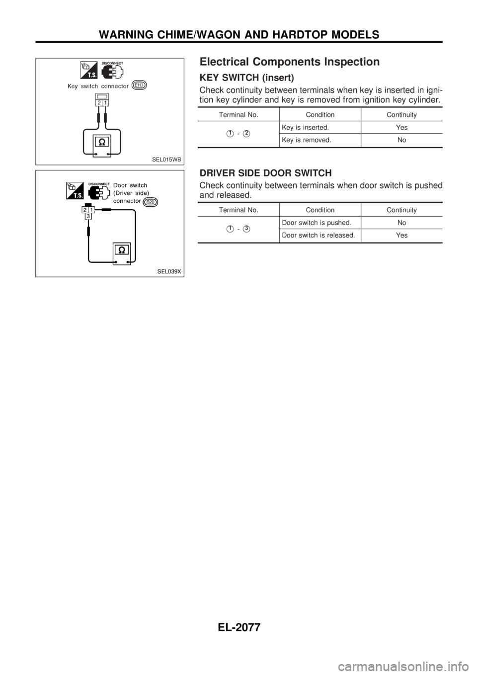
Electrical Components Inspection
KEY SWITCH (insert)
Check continuity between terminals when key is inserted in igni-
tion key cylinder and key is removed from ignition key cylinder.
Terminal No. Condition Continuity
V1-V2Key is inserted. Yes
Key is removed. No
DRIVER SIDE DOOR SWITCH
Check continuity between terminals when door switch is pushed
and released.
Terminal No. Condition Continuity
V1-V3Door switch is pushed. No
Door switch is released. Yes
SEL015WB
SEL039X
WARNING CHIME/WAGON AND HARDTOP MODELS
EL-2077
Page 209 of 273
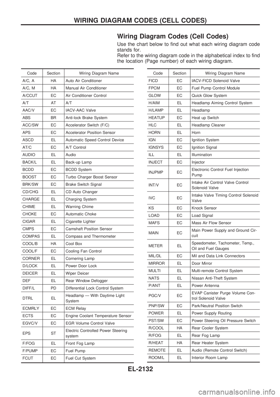
Wiring Diagram Codes (Cell Codes)
Use the chart below to find out what each wiring diagram code
stands for.
Refer to the wiring diagram code in the alphabetical index to find
the location (Page number) of each wiring diagram.
Code Section Wiring Diagram Name
A/C, A HA Auto Air Conditioner
A/C, M HA Manual Air Conditioner
A/CCUT EC Air Conditioner Control
A/T AT A/T
AAC/V EC IACV-AAC Valve
ABS BR Anti-lock Brake System
ACC/SW EC Accelerator Switch (F/C)
APS EC Accelerator Position Sensor
ASCD EL Automatic Speed Control Device
AT/C EC A/T Control
AUDIO EL Audio
BACK/L EL Back-up Lamp
BCDD EC BCDD System
BOOST EC Turbo Charger Boost Sensor
BRK/SW EC Brake Switch Signal
CD/CHG EL CD Auto Changer
CHARGE EL Charging System
CHIME EL Warning Chime
CHOKE EC Automatic Choke
CIGAR EL Cigarette Lighter
CMPS EC Camshaft Position Sensor
COMPAS EL Compass and Thermometer
COOL/B HA Cool Box
COOL/F EC Cooling Fan Control
CORNER EL Cornering Lamp
D/LOCK EL Power Door Lock
DEICER EL Wiper Deicer
DEF EL Rear Window Defogger
DIFF/L PD Differential Lock Control System
DTRL ELHeadlamp Ð With Daytime Light
System
ECMRLY EC ECM Relay
ECTS EC Engine Coolant Temperature Sensor
EGVC/V EC EGR Volume Control Valve
EPS STElectric Controlled Power Steering
system
F/FOG EL Front Fog Lamp
F/PUMP EC Fuel Pump
FCUT EC Fuel Cut SystemCode Section Wiring Diagram Name
FICD EC IACV-FICD Solenoid Valve
FPCM EC Fuel Pump Control Module
GLOW EC Quick Glow System
H/AIM EL Headlamp Aiming Control System
H/LAMP EL Headlamp
HEATUP EC Heat up Switch
HLC EL Headlamp Cleaner
HORN EL Horn
IGN EC Ignition System
IGNSYS EC Ignition Signal
ILL EL Illumination
INJECT EC Injector
INJPMP ECElectronic Control Fuel Injection
Pump
INT/V ECIntake Air Control Valve Control
Solenoid Valve
IVC ECIntake Valve Timing Control Solenoid
Valve
KS EC Knock Sensor
LOAD EC Load Signal
MAFS EC Mass Air Flow Sensor
MAIN ECMain Power Supply and Ground Cir-
cuit
METER ELSpeedometer, Tachometer, Temp.,
Oil and Fuel Gauges
MIL/DL EC Mil and Data Link Connectors
MIRROR EL Door Mirror
MULTI EL Multi-remote Control System
NATS EL Nissan Anti-Theft System
P/ANT EL Power Antenna
PGC/V ECEVAP Canister Purge Volume Con-
trol Solenoid Valve
PNP/SW EC Park/Neutral Position Switch
POWER EL Power Supply Routing
PST/SW EC Power Steering Oil Pressure Switch
R/COOL HA Rear Cooler System
R/FOG EL Rear Fog Lamp
R/HEAT HA Rear Heater System
REMOTE EL Audio (Remote Control Switch)
ROOM/L EL Interior Room Lamp
WIRING DIAGRAM CODES (CELL CODES)
EL-2132
Page 210 of 273
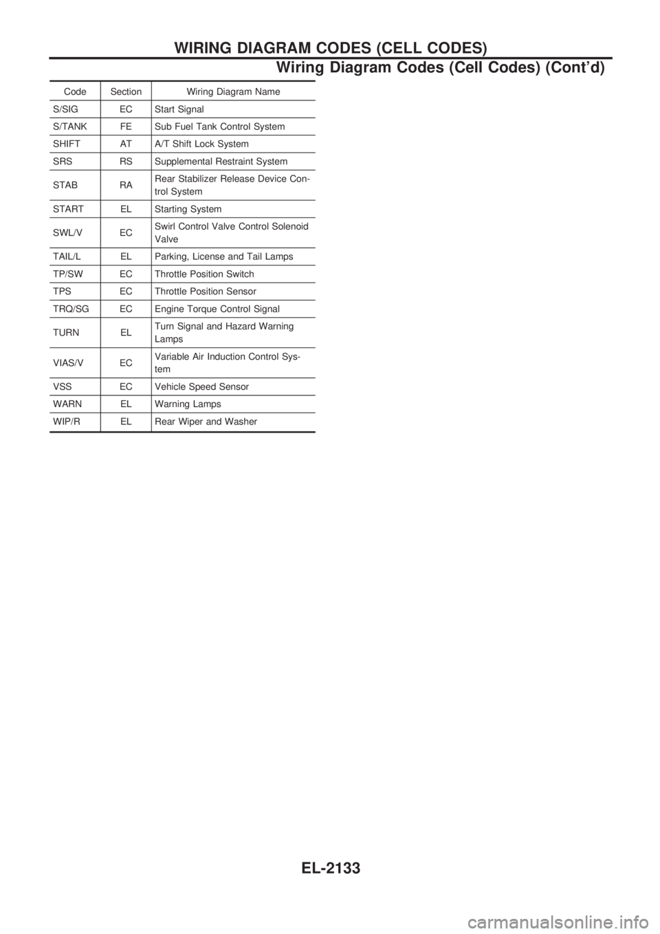
Code Section Wiring Diagram Name
S/SIG EC Start Signal
S/TANK FE Sub Fuel Tank Control System
SHIFT AT A/T Shift Lock System
SRS RS Supplemental Restraint System
STAB RARear Stabilizer Release Device Con-
trol System
START EL Starting System
SWL/V ECSwirl Control Valve Control Solenoid
Valve
TAIL/L EL Parking, License and Tail Lamps
TP/SW EC Throttle Position Switch
TPS EC Throttle Position Sensor
TRQ/SG EC Engine Torque Control Signal
TURN ELTurn Signal and Hazard Warning
Lamps
VIAS/V ECVariable Air Induction Control Sys-
tem
VSS EC Vehicle Speed Sensor
WARN EL Warning Lamps
WIP/R EL Rear Wiper and Washer
WIRING DIAGRAM CODES (CELL CODES)
Wiring Diagram Codes (Cell Codes) (Cont'd)
EL-2133
Page 221 of 273
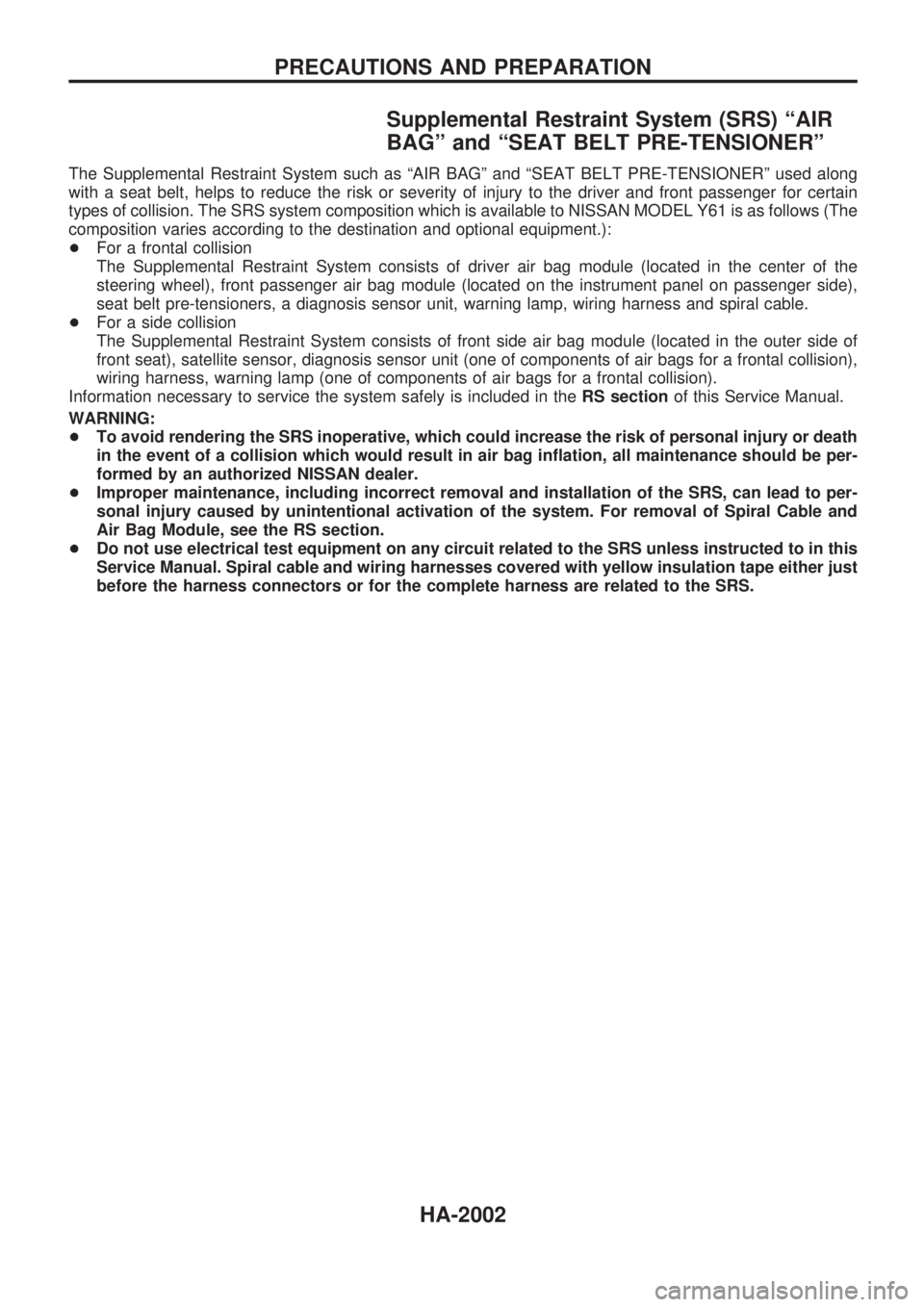
Supplemental Restraint System (SRS) ªAIR
BAGº and ªSEAT BELT PRE-TENSIONERº
The Supplemental Restraint System such as ªAIR BAGº and ªSEAT BELT PRE-TENSIONERº used along
with a seat belt, helps to reduce the risk or severity of injury to the driver and front passenger for certain
types of collision. The SRS system composition which is available to NISSAN MODEL Y61 is as follows (The
composition varies according to the destination and optional equipment.):
+For a frontal collision
The Supplemental Restraint System consists of driver air bag module (located in the center of the
steering wheel), front passenger air bag module (located on the instrument panel on passenger side),
seat belt pre-tensioners, a diagnosis sensor unit, warning lamp, wiring harness and spiral cable.
+For a side collision
The Supplemental Restraint System consists of front side air bag module (located in the outer side of
front seat), satellite sensor, diagnosis sensor unit (one of components of air bags for a frontal collision),
wiring harness, warning lamp (one of components of air bags for a frontal collision).
Information necessary to service the system safely is included in theRS sectionof this Service Manual.
WARNING:
+To avoid rendering the SRS inoperative, which could increase the risk of personal injury or death
in the event of a collision which would result in air bag inflation, all maintenance should be per-
formed by an authorized NISSAN dealer.
+Improper maintenance, including incorrect removal and installation of the SRS, can lead to per-
sonal injury caused by unintentional activation of the system. For removal of Spiral Cable and
Air Bag Module, see the RS section.
+Do not use electrical test equipment on any circuit related to the SRS unless instructed to in this
Service Manual. Spiral cable and wiring harnesses covered with yellow insulation tape either just
before the harness connectors or for the complete harness are related to the SRS.
PRECAUTIONS AND PREPARATION
HA-2002
Page 233 of 273
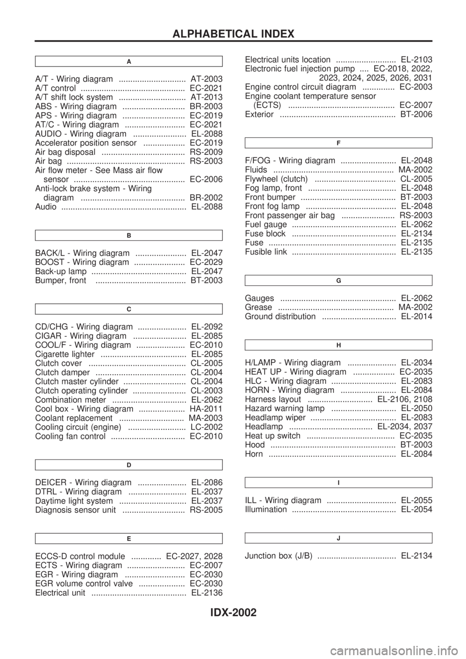
A
A/T - Wiring diagram ............................. AT-2003
A/T control ............................................. EC-2021
A/T shift lock system ............................. AT-2013
ABS - Wiring diagram ........................... BR-2003
APS - Wiring diagram ........................... EC-2019
AT/C - Wiring diagram .......................... EC-2021
AUDIO - Wiring diagram ....................... EL-2088
Accelerator position sensor .................. EC-2019
Air bag disposal .................................... RS-2009
Air bag ................................................... RS-2003
Air flow meter - See Mass air flow
sensor ................................................ EC-2006
Anti-lock brake system - Wiring
diagram ............................................. BR-2002
Audio ...................................................... EL-2088
B
BACK/L - Wiring diagram ...................... EL-2047
BOOST - Wiring diagram ...................... EC-2029
Back-up lamp ......................................... EL-2047
Bumper, front ....................................... BT-2003
C
CD/CHG - Wiring diagram ..................... EL-2092
CIGAR - Wiring diagram ....................... EL-2085
COOL/F - Wiring diagram ..................... EC-2010
Cigarette lighter ..................................... EL-2085
Clutch cover .......................................... CL-2005
Clutch damper ....................................... CL-2004
Clutch master cylinder ........................... CL-2004
Clutch operating cylinder ....................... CL-2003
Combination meter ................................ EL-2062
Cool box - Wiring diagram .................... HA-2011
Coolant replacement ............................ MA-2003
Cooling circuit (engine) ......................... LC-2002
Cooling fan control ................................ EC-2010
D
DEICER - Wiring diagram ..................... EL-2086
DTRL - Wiring diagram ......................... EL-2037
Daytime light system ............................. EL-2037
Diagnosis sensor unit ........................... RS-2005
E
ECCS-D control module ............. EC-2027, 2028
ECTS - Wiring diagram ......................... EC-2007
EGR - Wiring diagram .......................... EC-2030
EGR volume control valve .................... EC-2030
Electrical unit ......................................... EL-2136Electrical units location .......................... EL-2103
Electronic fuel injection pump .... EC-2018, 2022,
2023, 2024, 2025, 2026, 2031
Engine control circuit diagram .............. EC-2003
Engine coolant temperature sensor
(ECTS) .............................................. EC-2007
Exterior .................................................. BT-2006
F
F/FOG - Wiring diagram ........................ EL-2048
Fluids .................................................... MA-2002
Flywheel (clutch) ................................... CL-2005
Fog lamp, front ...................................... EL-2048
Front bumper ......................................... BT-2003
Front fog lamp ....................................... EL-2048
Front passenger air bag ....................... RS-2003
Fuel gauge ............................................. EL-2062
Fuse block ............................................. EL-2134
Fuse ....................................................... EL-2135
Fusible link ............................................. EL-2135
G
Gauges .................................................. EL-2062
Grease .................................................. MA-2002
Ground distribution ................................ EL-2014
H
H/LAMP - Wiring diagram ..................... EL-2034
HEAT UP - Wiring diagram .................. EC-2035
HLC - Wiring diagram ............................ EL-2083
HORN - Wiring diagram ........................ EL-2084
Harness layout ............................ EL-2106, 2108
Hazard warning lamp ............................ EL-2050
Headlamp wiper ..................................... EL-2083
Headlamp .................................... EL-2034, 2037
Heat up switch ...................................... EC-2035
Hood ...................................................... BT-2003
Horn ....................................................... EL-2084
I
ILL - Wiring diagram .............................. EL-2055
Illumination ............................................. EL-2054
J
Junction box (J/B) .................................. EL-2134
ALPHABETICAL INDEX
IDX-2002
Page 234 of 273
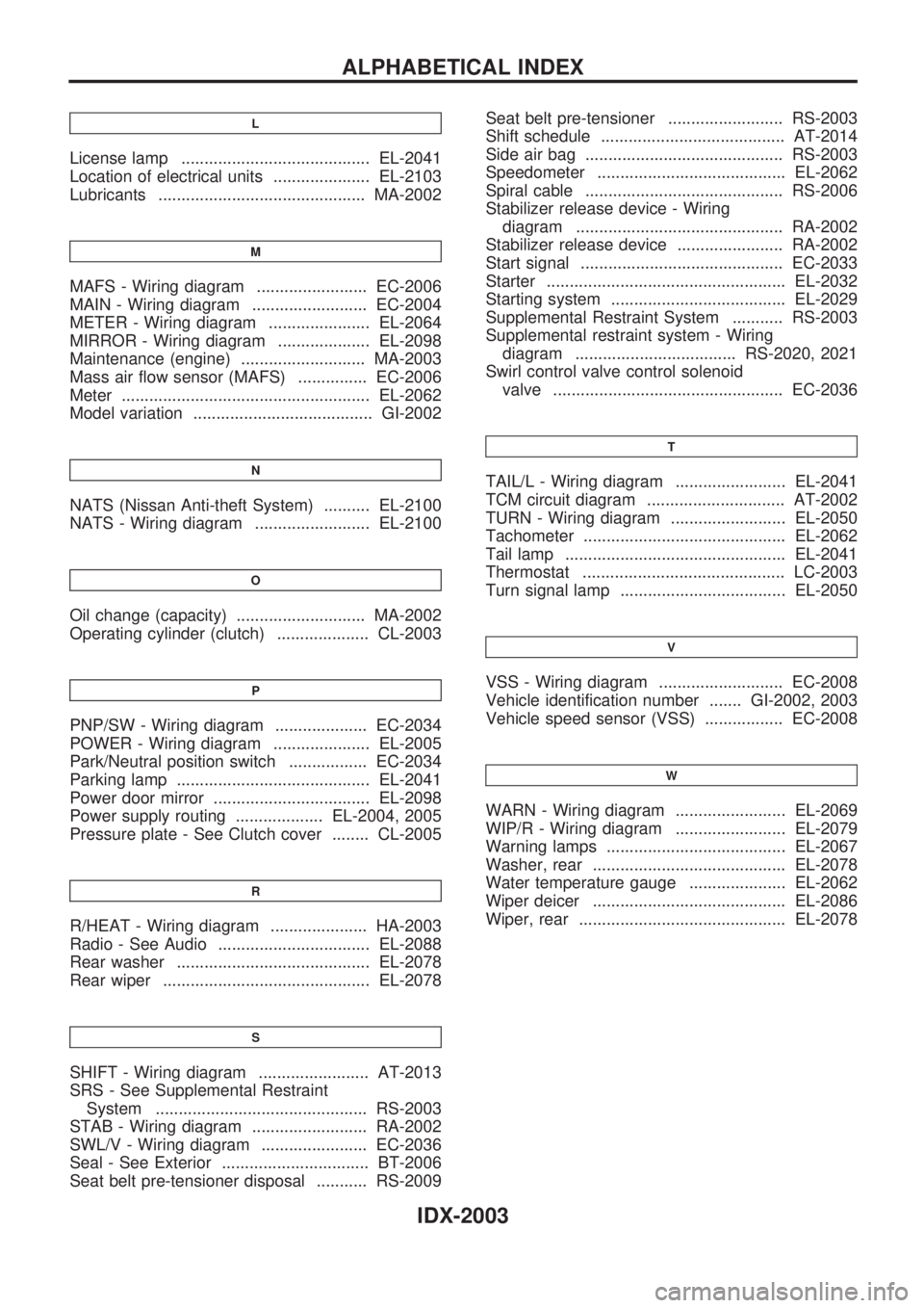
L
License lamp ......................................... EL-2041
Location of electrical units ..................... EL-2103
Lubricants ............................................. MA-2002
M
MAFS - Wiring diagram ........................ EC-2006
MAIN - Wiring diagram ......................... EC-2004
METER - Wiring diagram ...................... EL-2064
MIRROR - Wiring diagram .................... EL-2098
Maintenance (engine) ........................... MA-2003
Mass air flow sensor (MAFS) ............... EC-2006
Meter ...................................................... EL-2062
Model variation ....................................... GI-2002
N
NATS (Nissan Anti-theft System) .......... EL-2100
NATS - Wiring diagram ......................... EL-2100
O
Oil change (capacity) ............................ MA-2002
Operating cylinder (clutch) .................... CL-2003
P
PNP/SW - Wiring diagram .................... EC-2034
POWER - Wiring diagram ..................... EL-2005
Park/Neutral position switch ................. EC-2034
Parking lamp .......................................... EL-2041
Power door mirror .................................. EL-2098
Power supply routing ................... EL-2004, 2005
Pressure plate - See Clutch cover ........ CL-2005
R
R/HEAT - Wiring diagram ..................... HA-2003
Radio - See Audio ................................. EL-2088
Rear washer .......................................... EL-2078
Rear wiper ............................................. EL-2078
S
SHIFT - Wiring diagram ........................ AT-2013
SRS - See Supplemental Restraint
System .............................................. RS-2003
STAB - Wiring diagram ......................... RA-2002
SWL/V - Wiring diagram ....................... EC-2036
Seal - See Exterior ................................ BT-2006
Seat belt pre-tensioner disposal ........... RS-2009Seat belt pre-tensioner ......................... RS-2003
Shift schedule ........................................ AT-2014
Side air bag ........................................... RS-2003
Speedometer ......................................... EL-2062
Spiral cable ........................................... RS-2006
Stabilizer release device - Wiring
diagram ............................................. RA-2002
Stabilizer release device ....................... RA-2002
Start signal ............................................ EC-2033
Starter .................................................... EL-2032
Starting system ...................................... EL-2029
Supplemental Restraint System ........... RS-2003
Supplemental restraint system - Wiring
diagram ................................... RS-2020, 2021
Swirl control valve control solenoid
valve .................................................. EC-2036
T
TAIL/L - Wiring diagram ........................ EL-2041
TCM circuit diagram .............................. AT-2002
TURN - Wiring diagram ......................... EL-2050
Tachometer ............................................ EL-2062
Tail lamp ................................................ EL-2041
Thermostat ............................................ LC-2003
Turn signal lamp .................................... EL-2050
V
VSS - Wiring diagram ........................... EC-2008
Vehicle identification number ....... GI-2002, 2003
Vehicle speed sensor (VSS) ................. EC-2008
W
WARN - Wiring diagram ........................ EL-2069
WIP/R - Wiring diagram ........................ EL-2079
Warning lamps ....................................... EL-2067
Washer, rear .......................................... EL-2078
Water temperature gauge ..................... EL-2062
Wiper deicer .......................................... EL-2086
Wiper, rear ............................................. EL-2078
ALPHABETICAL INDEX
IDX-2003