Page 249 of 273
Wiring Diagram
TRA001
STABILIZER RELEASE DEVICE
RA-2002
Page 250 of 273
TRA006M
STABILIZER RELEASE DEVICE
Wiring Diagram (Cont'd)
RA-2003
Page 252 of 273

RESTRAINT SYSTEM
SECTION
RS
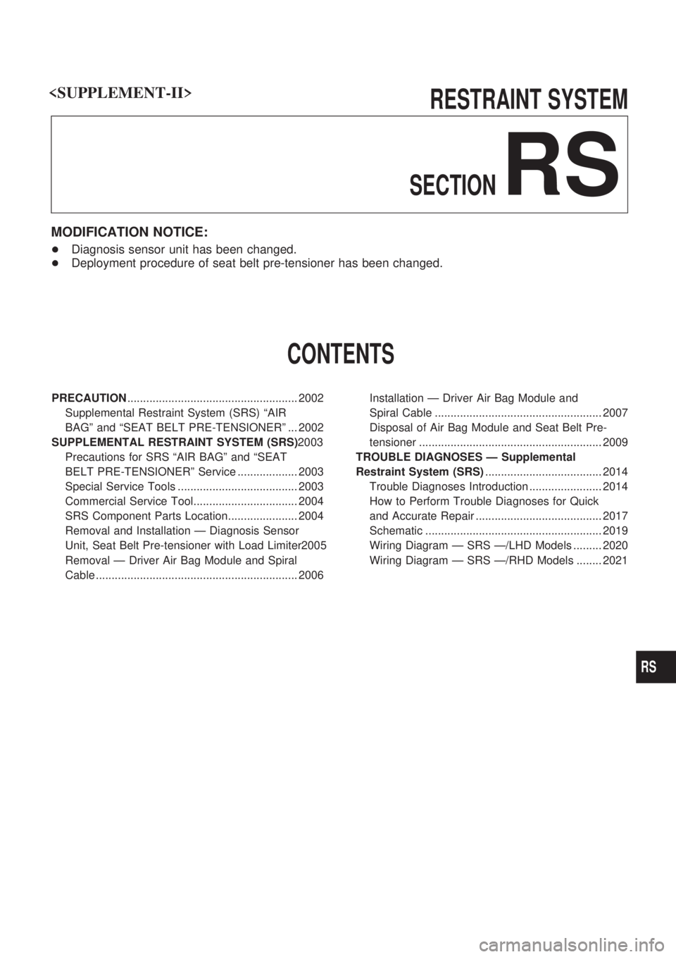
MODIFICATION NOTICE:
+Diagnosis sensor unit has been changed.
+Deployment procedure of seat belt pre-tensioner has been changed.
CONTENTS
PRECAUTION...................................................... 2002
Supplemental Restraint System (SRS) ªAIR
BAGº and ªSEAT BELT PRE-TENSIONERº ... 2002
SUPPLEMENTAL RESTRAINT SYSTEM (SRS)2003
Precautions for SRS ªAIR BAGº and ªSEAT
BELT PRE-TENSIONERº Service ................... 2003
Special Service Tools ...................................... 2003
Commercial Service Tool................................. 2004
SRS Component Parts Location...................... 2004
Removal and Installation Ð Diagnosis Sensor
Unit, Seat Belt Pre-tensioner with Load Limiter2005
Removal Ð Driver Air Bag Module and Spiral
Cable ................................................................ 2006Installation Ð Driver Air Bag Module and
Spiral Cable ..................................................... 2007
Disposal of Air Bag Module and Seat Belt Pre-
tensioner .......................................................... 2009
TROUBLE DIAGNOSES Ð Supplemental
Restraint System (SRS)..................................... 2014
Trouble Diagnoses Introduction ....................... 2014
How to Perform Trouble Diagnoses for Quick
and Accurate Repair ........................................ 2017
Schematic ........................................................ 2019
Wiring Diagram Ð SRS Ð/LHD Models ......... 2020
Wiring Diagram Ð SRS Ð/RHD Models ........ 2021
RS
Page 253 of 273

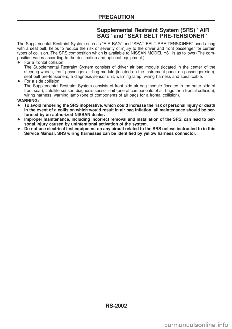
Supplemental Restraint System (SRS) ªAIR
BAGº and ªSEAT BELT PRE-TENSIONERº
The Supplemental Restraint System such as ªAIR BAGº and ªSEAT BELT PRE-TENSIONERº used along
with a seat belt, helps to reduce the risk or severity of injury to the driver and front passenger for certain
types of collision. The SRS composition which is available to NISSAN MODEL Y61 is as follows (The com-
position varies according to the destination and optional equipment.):
+For a frontal collision
The Supplemental Restraint System consists of driver air bag module (located in the center of the
steering wheel), front passenger air bag module (located on the instrument panel on passenger side),
seat belt pre-tensioners, a diagnosis sensor unit, warning lamp, wiring harness and spiral cable.
+For a side collision
The Supplemental Restraint System consists of front side air bag module (located in the outer side of
front seat), satellite sensor, diagnosis sensor unit (one of components of air bags for a frontal collision),
wiring harness, warning lamp (one of components of air bags for a frontal collision).
WARNING:
+To avoid rendering the SRS inoperative, which could increase the risk of personal injury or death
in the event of a collision which would result in air bag inflation, all maintenance should be per-
formed by an authorized NISSAN dealer.
+Improper maintenance, including incorrect removal and installation of the SRS, can lead to per-
sonal injury caused by unintentional activation of the system.
+Do not use electrical test equipment on any circuit related to the SRS unless instructed to in this
Service Manual. SRS wiring harnesses can be identified by yellow harness connector.
PRECAUTION
RS-2002
Page 265 of 273

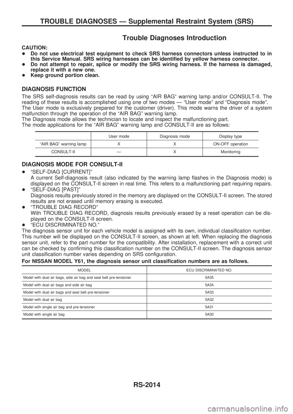
Trouble Diagnoses Introduction
CAUTION:
+Do not use electrical test equipment to check SRS harness connectors unless instructed to in
this Service Manual. SRS wiring harnesses can be identified by yellow harness connector.
+Do not attempt to repair, splice or modify the SRS wiring harness. If the harness is damaged,
replace it with a new one.
+Keep ground portion clean.
DIAGNOSIS FUNCTION
The SRS self-diagnosis results can be read by using ªAIR BAGº warning lamp and/or CONSULT-II. The
reading of these results is accomplished using one of two modes Ð ªUser modeº and ªDiagnosis modeº.
The User mode is exclusively prepared for the customer (driver). This mode warns the driver of a system
malfunction through the operation of the ªAIR BAGº warning lamp.
The Diagnosis mode allows the technician to locate and inspect the malfunctioning part.
The mode applications for the ªAIR BAGº warning lamp and CONSULT-II are as follows:
User mode Diagnosis mode Display type
ªAIR BAGº warning lamp X X ON-OFF operation
CONSULT-II Ð X Monitoring
DIAGNOSIS MODE FOR CONSULT-II
+ªSELF-DIAG [CURRENT]º
A current Self-diagnosis result (also indicated by the warning lamp flashes in the Diagnosis mode) is
displayed on the CONSULT-II screen in real time. This refers to a malfunctioning part requiring repairs.
+ªSELF-DIAG [PAST]º
Diagnosis results previously stored in the memory are displayed on the CONSULT-II screen. The stored
results are not erased until memory erasing is executed.
+ªTROUBLE DIAG RECORDº
With TROUBLE DIAG RECORD, diagnosis results previously erased by a reset operation can be dis-
played on the CONSULT-II screen.
+ªECU DISCRIMINATED NO.º
The diagnosis sensor unit for each vehicle model is assigned with its own, individual classification number.
This number will be displayed on the CONSULT-II screen, as shown at left. When replacing the diagnosis
sensor unit, refer to the part number for the compatibility. After installation, replacement with a correct unit
can be checked by confirming this classification number on the CONSULT-II screen. The diagnosis sensor
unit classification number varies depending on SRS configuration.
For NISSAN MODEL Y61, the diagnosis sensor unit classification numbers are as follows.
MODEL ECU DISCRIMINATED NO.
Model with dual air bags, side air bag and seat belt pre-tensioner 5A35
Model with dual air bags and side air bag 5A34
Model with dual air bags and seat belt pre-tensioner 5A33
Model with dual air bag5A32
Model with single air bag and pre-tensioner 5A31
Model with single air bag5A30
TROUBLE DIAGNOSES Ð Supplemental Restraint System (SRS)
RS-2014
Page 271 of 273
Wiring Diagram Ð SRS Ð/LHD Models
LHD MODELS
TRS038M
TROUBLE DIAGNOSES Ð Supplemental Restraint System (SRS)
RS-2020
Page 272 of 273
Wiring Diagram Ð SRS Ð/RHD Models
RHD MODELS
TRS044M
TROUBLE DIAGNOSES Ð Supplemental Restraint System (SRS)
RS-2021